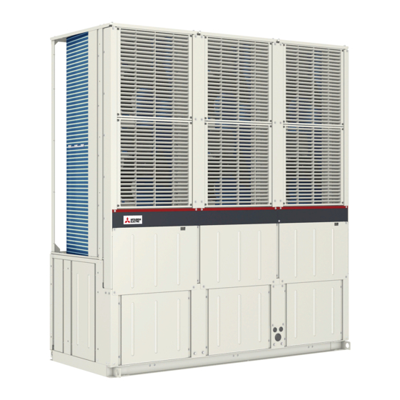
Mitsubishi Electric e Series Service Handbook
Air-cooled chilling unit r410a
Hide thumbs
Also See for e Series:
- Service handbook (176 pages) ,
- Installation & operation manual (88 pages)
Table of Contents
Advertisement
Advertisement
Table of Contents
Troubleshooting

Related Manuals for Mitsubishi Electric e Series


Summary of Contents for Mitsubishi Electric e Series
- Page 2 Indicates a risk of injury or structural damage Indicates a risk of damage to the unit or other components in the system IMPORTANT All electric work must be performed by personnel certified by Mitsubishi Electric. General WARNING To reduce the risk of injury, keep children away while Do not use refrigerant other than the type indicated in installing, inspecting, or repairing the unit.
- Page 3 CAUTION To reduce the risk of fire or explosion, do not place flammable To prevent environmental pollution, dispose of brine in materials or use flammable sprays around the unit. the unit and cleaning solutions according to the local regulations. Do not operate the unit without panels and safety guards properly installed.
- Page 4 Any additional parts must be installed by qualified personnel. Only use the parts specified by Mitsubishi Electric. Properly dispose of the packing materials. Plastic bags pose suffocation hazard to children. Take appropriate safety measures against wind gusts and...
- Page 5 To reduce the risk of injury or electric shock, switch off the To reduce the risk of current leakage, overheating, smoke, or main power before performing electrical work. fire, use properly rated cables with adequate current carrying capacity. All electric work must be performed by a qualified electrician according to the local regulations, standards, Keep the unsheathed part of cables inside the terminal and the instructions detailed in the Installation Manual.
- Page 6 Please build the water circuit so that it is a closed Check the water system, using a relevant manual as a system. reference. Do not use water directly for showers or other applications. Using the system that does not meet the standards (including Do not allow other heat source water to mix with the water water quality and water flow rate) may cause the water pipes circuit.
- Page 7 HWE1417B...
-
Page 8: Table Of Contents
CONTENTS I Read Before Servicing [1] Read Before Servicing......................3 [2] Necessary Tools and Materials ....................4 [3] Brazing............................5 [4] Air Tightness Test........................6 [5] Vacuum Drying (Evacuation) ....................7 [6] Refrigerant Charging ........................ 8 [7] Remedies to be taken in case of a Refrigerant Leak..............8 [8] Characteristics of the Conventional and the New Refrigerants .......... - Page 9 CONTENTS HWE1417B...
- Page 10 I Read Before Servicing [1] Read Before Servicing ....................... 3 [2] Necessary Tools and Materials..................4 [3] Brazing..........................5 [4] Air Tightness Test ......................6 [5] Vacuum Drying (Evacuation) ..................... 7 [6] Refrigerant Charging......................8 [7] Remedies to be taken in case of a Refrigerant Leak ............8 [8] Characteristics of the Conventional and the New Refrigerants .........
- Page 11 - 2 - HWE1417B...
-
Page 12: Read Before Servicing
[ I Read Before Servicing ] I Read Before Servicing [1] Read Before Servicing 1. Check the type of refrigerant used in the system to be serviced. Refrigerant Type Air-coold Chilling Unit e-series EAHV/EACV-P900YA: R410A 2. Check the symptoms exhibited by the unit to be serviced. Refer to this service handbook for symptoms relating to the refrigerant cycle. -
Page 13: Necessary Tools And Materials
[ I Read Before Servicing ] [2] Necessary Tools and Materials Prepare the following tools and materials necessary for servicing the unit. Tools for use with R410A (Adaptability of tools that are for use with R22 or R407C) 1. To be used exclusively with R410A (not to be used if used with R22 or R407C) Tools/Materials Notes Gauge Manifold... -
Page 14: Brazing
[ I Read Before Servicing ] [3] Brazing No changes have been made in the brazing procedures. Perform brazing with special care to keep foreign objects (such as oxide scale, water, and dust) out of the refrigerant system. Example: Inside the brazed connection Use of oxidized solder for brazing Use of non-oxidized solder for brazing 1. -
Page 15: Air Tightness Test
[ I Read Before Servicing ] [4] Air Tightness Test No changes have been made in the detection method. Note that a refrigerant leak detector for R22 will not detect an R410A leak. Halide torch R22 leakage detector 1. Items to be strictly observed Pressurize the equipment with nitrogen up to the design pressure (4.15MPa), and then judge the equipment's air tightness, taking temperature variations into account. -
Page 16: Vacuum Drying (Evacuation)
[ I Read Before Servicing ] [5] Vacuum Drying (Evacuation) (Photo1) 15010H (Photo2) 14010 Recommended vacuum gauge: ROBINAIR 14010 Thermistor Vacuum Gauge 1. Vacuum pump with a reverse-flow check valve (Photo1) To prevent the vacuum pump oil from flowing into the refrigerant circuit during power OFF or power failure, use a vacuum pump with a reverse-flow check valve. -
Page 17: Refrigerant Charging
[ I Read Before Servicing ] [6] Refrigerant Charging Cylinder with a siphon Cylinder without a siphon Cylin- Cylin- Cylinder color R410A is Pink. Refrigerant charging in the liquid state Valve Valve liquid liquid Charge refrigerant through the Charging refrigerant through the check joint on the high-pressure side. -
Page 18: Characteristics Of The Conventional And The New Refrigerants
[ I Read Before Servicing ] [8] Characteristics of the Conventional and the New Refrigerants 1. Chemical property As with R22, the new refrigerant (R410A) is low in toxicity and chemically stable nonflammable refrigerant. However, because the specific gravity of vapor refrigerant is greater than that of air, leaked refrigerant in a closed room will accumulate at the bottom of the room and may cause hypoxia. -
Page 19: Notes On Refrigerating Machine Oil
[ I Read Before Servicing ] [9] Notes on Refrigerating Machine Oil 1. Refrigerating machine oil in the HFC refrigerant system HFC type refrigerants use a refrigerating machine oil different from that used in the R22 system. Note that the ester oil used in the system has properties that are different from commercially available ester oil. Refrigerant Refrigerating machine oil Mineral oil... -
Page 20: Restrictions
II Restrictions [1] System Configuration....................... 13 [2] Types and Maximum allowable Length of Cables ............14 [3] Electrical Wiring Installation ..................... 15 [4] Sample Installation......................18 [5] Switch Types and the Factory Settings................19 [6] Configuring the Settings....................20 [7] Water Pipe Installation ..................... 27 - 11 - HWE1417B... - Page 21 - 12 - HWE1417B...
-
Page 22: System Configuration
[ II Restrictions ] II Restrictions [1] System Configuration The system must be configured only by personnel certified by Mitsubishi Electric. [1] Schematic Diagrams of Individual and Multiple Module Connection Systems (1) Individual system External temperature sensor (option) MAIN Flow switch... -
Page 23: Types And Maximum Allowable Length Of Cables
[ II Restrictions ] [2] Types and Maximum allowable Length of Cables 1. Wiring work (1) Notes 1) Have all electrical work performed by an authorized electrician according to the local regulations and instructions in this man- ual. 2) Install external transmission cables at least 5cm [1-31/32"] away from the power supply cable to avoid noise interference. (Do not put the control cable and power supply cable in the same conduit tube.) 3) Provide grounding for the unit as required. -
Page 24: Electrical Wiring Installation
[ II Restrictions ] [3] Electrical Wiring Installation 1 Main Power Supply Wiring and Switch Capacity Schematic Drawing of Wiring (Example) : Switch (with current breaking capability) 3N~380–415V : Current leakage breaker : Unit Main power supply wire size, switch capacities, and system impedance Local swtich (A) Minimum wire thickness (mm Max. - Page 25 [ II Restrictions ] Control cable specifications Size 0.3 mm² (Max. 200 m total)*2 Remote controller cable ( ² M-NET cable between units External input wire size Min. 0.3 mm² External output wire size 1.25 mm² *1 Use a CVVS or CPEVS cable (Max. total length of 200 m) if there is a source of electrical interference near by (e.g., factory) or the total length of control wiring exceeds 120 m.
- Page 26 [ II Restrictions ] 1. Check that the spring washer is in a parallel position. * If the screw is biting into the washer, simply fastening the screw to the specified torque cannot determine whether it has been installed properly. Properly installed Loose screws Spring washer is in a parallel position...
-
Page 27: Sample Installation
[ II Restrictions ] [4] Sample Installation The system must be configured only by personnel certified by Mitsubishi Electric. [1] Schematic Diagrams of Individual and Multiple Module Connection Systems (1) Individual system External temperature sensor (option) MAIN Flow switch Pump interlock Set point controlled with either: •PAR-W21MAA or PAR-W31MAA... -
Page 28: Switch Types And The Factory Settings
[ II Restrictions ] [5] Switch Types and the Factory Settings (1) Switch names and functions Control box Control box (Sub circuit) (Main circuit) There are four main ways to set the settings as follows: 1 Dip switches (SW1 - SW3, SW421) 2 Dip switches used in combination with the push switches 3 Rotary switches 4 Slide switches... -
Page 29: Configuring The Settings
[ II Restrictions ] [6] Configuring the Settings The settings must be set only by a qualified personnel. <1> Making the settings Use the LED display and the three push switches (SWP1 (↑), SWP2 (↓), and SWP3 (Enter)) to change the current settings on the circuit board and to monitor various monitored values. - Page 30 [ II Restrictions ] (2) Table of settings items Set the dip switch SW1 as shown in the table below to set the value for the items in the "Setting item" column. Need or non- need to set the setting *6 MAIN Dip switch setting (SW1) *1 Setting Item...
- Page 31 [ II Restrictions ] <2> System configuration (1) System configuration procedures: Individual system 1. Set the dip switches on the circuit board. Switch settings on the MAIN and SUB circuit Set the dip switches (labeled A and B in the figure below) that correspond to the items below, according to the local system. •...
- Page 32 [ II Restrictions ] Within 50 seconds after the power is switched on, the following codes will appear on the LED: • [****] will appear on LED1 in the MAIN circuit board (labeled A in the figure above). • [0000]→[****] will appear on LED1 in the SUB circuit board (labeled B in the figure above). **** Model 0000...
- Page 33 [ II Restrictions ] Setting the switches on all sub modules MAIN circuit (1) Set the MAIN circuit addresses with the rotary switches. (labeled A in the figure below). Set the 10's digit with SWU1, and set the 1's digit with SWU2. Assign sequential addresses to the MAIN circuit on all sub modules starting with 2.
- Page 34 [ II Restrictions ] 2. Switch on the power to the unit. Check for loose or incorrect wiring, and then switch on the power to all modules. When the power is switched on, the following codes will appear on the LED: •...
- Page 35 [ II Restrictions ] 3. Perform an initial setup on the main and sub modules Perform the initial setup of all modules in accordance with the table below. Dip switch setting (SW1) Setting Item Main module Sub module Default ■:ON □:OFF Setting the total number of modules *Change the setting to "0"...
-
Page 36: Water Pipe Installation
[ II Restrictions ] [7] Water Pipe Installation 1. Schematic Piping Diagram and Piping System Components <1> Water circuit Please build the water circuit so that it is a closed Condensation may form in the machine room, depending system. on the operation status. Do not use water directly for showers or other applications. - Page 37 [ II Restrictions ] <2> Brine circuit Indicates the direction of the flow. Unit Cooling for industrial process Water side heat exchanger Union joints/flange joints Required to allow for a replacement of equipment. Thermometer Required to check the performance and monitor the operation of the units. Water pressure gauge Recommended for checking the operation status.
- Page 38 [ II Restrictions ] 2. Water piping attachment method Standard piping type Water outlet Water inlet 50A housing type joint (field-supplied Victaulic joint)* * Victaulic standard groove specifications Machine grooves to secure housing joints to field-supplied pipes based on the following dimensions. Pipe size ø60.3 ±...
- Page 39 [ II Restrictions ] On-site module connection and terminal work The module connection requires the option of both Inside header piping kit (EA-01HK) and Inside header connecting kit (EA-02HK). Inside header connecting kit requires the same number as the number of connections. Option Parts: EA-01HK EA-02HK * Refer to the installation instructions for the details of installation of the optional parts.
- Page 40 [ II Restrictions ] 3. Notes on pipe corrosion Water treatment and water quality control Poor-quality circulating water can cause the water-side heat exchanger to scale up or corrode, reducing heat- exchange performance. Properly control the quality of the circulating water. •...
- Page 41 [ II Restrictions ] (5) Suspended solids in the water Sand, pebbles, suspended solids, and corrosion products in water can damage the heating surface of the heat exchanger and cause corrosion. Install a good quality strainer (20 mesh or better) at the inlet of the unit to filter out suspended solids.
- Page 42 [ II Restrictions ] 4. Installing the strainer and flow switch (1) Installing the strainer Install a strainer on the inlet pipe near the unit to filter out suspended solids and prevent clogging or corrosion of the heat exchanger. Install a strainer in a way that allows for easy access for cleaning, and instruct the user to clean it regularly. Operating the units with a clogged strainer may cause the units to make an abnormal stop.
- Page 43 [ II Restrictions ] 5. Minimum and maximum water flow rates A low flow rate will not only compromise the performance of the unit but also increase the water temperature difference be- tween the periods when the unit is in operation and when the unit is stopped. A high flow rate will cause the pipes to corrode. Adjust the circulating flow rate so that the difference between the inlet and outlet temperatures will be between 3 ºC and 10 ºC.
- Page 44 [ II Restrictions ] 8. Water Piping Size and Location <1> Standard piping type Water outlet 50A housing type joint Water inlet 50A housing type joint Drain 1017 Drain Drain <2> Inside header piping type Water outlet Water outlet 100A housing type joint 100A housing type joint (Case of right side piping) (Case of left side piping)
- Page 45 [ II Restrictions ] - 36 - HWE1417B...
-
Page 46: Unit Components
III Unit Components [1] Unit Components and Refrigerant Circuit ................ 39 [2] Control Box of the Unit..................... 43 [3] Unit Circuit Board......................45 - 37 - HWE1417B... - Page 47 - 38 - HWE1417B...
-
Page 48: Unit Components And Refrigerant Circuit
[ III Unit Components ] III Unit Components [1] Unit Components and Refrigerant Circuit 1. Unit Components Pillar M Panel assy T Air guide Decorative panel SL Panel S Decorative panel SR Panel SL Panel S1 Panel M Panel SR Panel F Wiring window cover Pillar assy R... - Page 49 [ III Unit Components ] Fan motor SUB CONTROL BOX TERMINAL BOX FAN CONTROL BOX MAIN CONTROL BOX - 40 - HWE1417B...
- Page 50 [ III Unit Components ] 2. Refrigerant circuit Linear expansion valve Linear expansion valve Water-side Scroll compressor (SUB) heat exchanger assy Thermistor (TH11) Scroll compressor Water-side Thermistor (TH21) Check joint Check joint (MAIN) heat exchanger assy Pressure Pressure sensor LP sensor LP Pressure sensor HP...
- Page 51 [ III Unit Components ] Air purge valve Housing joint (50A) Thermistor (TH3) Housing joint (100A) Air purge valve Housing joint (100A) Ball valve <Inside header piping type> - 42 - HWE1417B...
-
Page 52: Control Box Of The Unit
[ III Unit Components ] [2] Control Box of the Unit (1) Main circuit control box Rush current protection resister DC reactor INV board Capacitor Control board (DCL) Electromagnetic relay (52C) Noise filter (Compressor) M-NET board Terminal block (TB1) (2) Sub circuit control box Rush current protection resister Capacitor INV board... - Page 53 [ III Unit Components ] (3) Fan control box Capacitor Diode bridge Capacitor Diode bridge Noise filter (Fan) Noise filter (Fan) Fan control board Fan control board 1) Exercise caution not to damage the bottom and the front panel of the control box. Damage to these parts affect the waterproof and dust proof properties of the control box and may result in damage to its internal components.
-
Page 54: Unit Circuit Board
[ III Unit Components ] [3] Unit Circuit Board 1. Control board (MAIN board) CN 2 CN801 Serial communication Pressure switch signal input connection Output 17VDC CN 4 CNDC Bus voltage input Serial communication signal output LED4 Energization status (CPU) driving output CN3A Remote controller... - Page 55 [ III Unit Components ] 2. M-NET board CNS2 CNIT Transmission line input/output for 12VDC input CN04 centralized control system CN102 Bus voltage input 5VDC input Power supply output for centralized control system Power supply detection output Indoor/outdoor transmission line input/output Power supply ON/OFF Grounding signal input...
- Page 56 [ III Unit Components ] 3. INV board SC-P1 Rectifier diode output (P) Open: No-load operation setting CN5V RSH1 SC-P2 Short-circuited: Normal setting LED1 Overcurrent detection Bus voltage Input(P) Lit: Inverter in normal operation 5VDC output resistor Blink: Inverter error CN43 GND(Control Board) Serial communication...
- Page 57 [ III Unit Components ] 4. Noise Filter (Compressor) Output Output (Rectified L2-N current) (Rectified L2-N current) Surge absorber circuit Surge absorber circuit Short circuit Short circuit Grounding F1,F2,F3,F4 Fuse 250VAC 6.3A Output Grounding CN1A Input CN1B TB21 TB22 TB23 TB24 Input Input/output(L1)
- Page 58 [ III Unit Components ] 5. Fan control board CN2A 18VDC input CNDC Serial communication Bus voltage input signal output 17VDC input 17VDC input CN4A Serial communication signal input CN4B Serial communication signal output CN2B 5VDC input Serial communication signal input 17VDC input 17VDC input CNF1...
- Page 59 [ III Unit Components ] 6. Noise Filter (Fan) CNACL Open:No-load operation setting Short-circuited: normal setting CNR1 To R13 or R23 CNDB AC output Bus voltage input CNFAN Bus voltage output CNXB1 X010 ON 12VDC input CNDP L2 or L3 - 50 - HWE1417B...
-
Page 60: Remote Controller
IV Remote Controller [1] Using the Remote Controller (PAR-W21MAA) ..............53 [2] Using the Remote Controller (PAR-W31MAA) ..............60 - 51 - HWE1417B... - Page 61 - 52 - HWE1417B...
-
Page 62: Using The Remote Controller (Par-W21Maa)
[ IV Remote Controller ] IV Remote Controller [1] Using the Remote Controller (PAR-W21MAA) <1> Starting and Stopping Operation and To Stop Operation Changing the Operation Mode 1. Press the ON/OFF (BACK) button while the unit is in operation. The power indicator and the display will light off. - Page 63 [ IV Remote Controller ] <2> Setting the Water Temperature How to Set the Day of the Week and Time The current water temperature will appear in the area Day of the Week Setting labeled TIME SUN Time Setting How to Change the Temperature Setting 1.
- Page 64 [ IV Remote Controller ] How to Set the Weekly Timer How to View the Weekly Timer Settings 1. On the Normal Operation screen, make sure that the weekly timer icon Time Settings is displayed. 2. Press the TIMER MENU button , so that the “Set Up”...
- Page 65 [ IV Remote Controller ] How to Set the Simple Timer To Turn Off the Simple Timer Press the TIMER ON/OFF button so that the timer setting no longer Time Setting appears on the screen (at Action (On or Off) AFTER “–...
- Page 66 [ IV Remote Controller ] Using the Auto-Off Timer Checking the Current Auto-Off Timer Setting 1. This timer begins countdown when the unit starts, and shuts the unit off Timer Setting when the set time has elapsed. 2. Available settings range from 30 minutes to 4 hours in 30-minute intervals. TIMER AFTER Note:...
- Page 67 [ IV Remote Controller ] <5> Function Settings The settings for the following remote controller functions can be changed using the remote controller function selection mode. Change the settings as necessary. Item 1 Item 2 Item 3 (Setting content) 1. Display language Display language selection •...
- Page 68 [ IV Remote Controller ] Settings details <5>-3. Basic functions (1) Remote controller main/sub setting <5>-1. Display language setting • Press the [ ON/OFF] button to toggle between the following options. The display language can be selected from the languages listed below. Main The controller will be designated as the main controller.
-
Page 69: Using The Remote Controller (Par-W31Maa)
[ IV Remote Controller ] [2] Using the Remote Controller (PAR-W31MAA) <1> Power ON/OFF Unit1 Press the [ON/OFF] button. During operation Next The ON/OFF lamp will light up in green, and the operation will start. Unit1 Pressing the [ON/OFF] button brings up a confirmation screen. When it appears, press the [F3] button. - Page 70 [ IV Remote Controller ] <3> Using Weekly timer Function description Following settings can be used to change the operating schedule according to the day of the week. • Set the schedule for ON/OFF, operation mode and set temperature for each day of the week. Button operation Select "Weekly timer"...
- Page 71 [ IV Remote Controller ] In the Operation setting screen, press the [F1] button to move the cursor to Unit1 "Schedule". Power Save Press the [F3] button to select "Yes". Schedule Fan Mode Normal Anti-freeze Next <4> Using Period timer Function description Following settings can be made to change the specified period and daily operating schedule.
- Page 72 [ IV Remote Controller ] The pattern setting screen will be displayed. Unit1 * Refer to the section on Weekly timer for details on using the pattern setting screen. Anti-Freeze Heating Weekly timer operation will be disabled in the following situations: •...
- Page 73 [ IV Remote Controller ] - 64 - HWE1417B...
- Page 74 V Electrical Wiring Diagram [1] Electrical Wiring Diagram....................67 - 65 - HWE1417B...
- Page 75 - 66 - HWE1417B...
-
Page 76: Electrical Wiring Diagram
[ V Electrical Wiring Diagram ] V Electrical Wiring Diagram [1] Electrical Wiring Diagram - 67 - HWE1417B... - Page 77 [ V Electrical Wiring Diagram ] C100 MAIN BOX R11,R12 DCL1 52C1 SC-P2 FT-P SC-P1 black Power supply INV Board 1 Noise Filter1-1 CN1A CN43 50/60Hz yellow FT-N TERMINAL CNTYP C30,C32 C31,C33 RSH1 ZNR001 CN1B C34,C36 C35,C37 R30,R32,R34 R31,R33,R35 CT12 TB21 SC-L1 SC-U...
- Page 78 [ V Electrical Wiring Diagram ] INV1-FAN1-6 FANCONT BOX CJ2-1 INV1-FAN1-5 Fan motor1-1 INV1-FAN1-4 MF1-1 CJ1-1 INV1-FAN1-3 INV1-FAN1-2 CJ4-1 INV1-FAN1-1 MF2-1 Fan motor2-1 CJ3-1 CJ6-1 MF3-1 Fan motor3-1 CJ5-1 INV1-FAN1-8 INV1-FAN1-7 CNDC CNF1 CNF2 CNF3 FANCONT Board1 CN4B CN2B CN4A CN2A Compressor1 CNACL...
- Page 79 [ V Electrical Wiring Diagram ] FAN control (front view) SUB CIRCUIT MAIN CIRCUIT Inside of the control box (front view) C200 SUB BOX FANCONT BOX 52C1 C100 MAIN BOX 52C2 DCL2 DCL1 Control Control Board 2 Board 1 Noise Noise Noise Noise...
- Page 80 [ V Electrical Wiring Diagram ] When using a local controller, refer to the table below for the types of input/output signals that are available and the operations that correspond to the signals. External Input/Output Input Dry contact ON (Close) OFF (Open) Terminal block type...
- Page 81 [ V Electrical Wiring Diagram ] Input and output correspondence table Terminal block MAIN module SUB module ○ TB5 K01-K02 Stop ○ Fan mode TB5 K01-K03 Forced Normal ○ Cooling/Heating switching TB5 K04-K05 Heating Cooling ○ ○* Pump interlock TB5 K04-K06 Normal Error ○...
-
Page 82: Refrigerant Circuit
VI Refrigerant Circuit [1] Refrigerant Circuit Diagram ..................... 75 [2] Principal Parts and Functions ..................76 - 73 - HWE1417B... - Page 83 - 74 - HWE1417B...
-
Page 84: Refrigerant Circuit Diagram
[ VI Refrigerant Circuit ] VI Refrigerant Circuit [1] Refrigerant Circuit Diagram EAHV-P900YA : Valve * (Only inside Air-side Air-side header piping type) heat exchange heat exchange : Check joint TH10 : Strainer : Y bend Air-side Air-side heat exchange heat exchange : Check valve HP1,2 High pressure... -
Page 85: Principal Parts And Functions
[ VI Refrigerant Circuit ] [2] Principal Parts and Functions 1. Outdoor unit Part Symbols Notes Usage Specifications Check method name (functions) Com- Adjusts the amount of circulat- Low-pressure shell scroll pres- (Comp) ing refrigerant by adjusting the compressor operating frequency based on Wirewound resistance the operating pressure data 20°C[68°F] : 0.092 ohm... - Page 86 [ VI Refrigerant Circuit ] Part Symbols Notes Usage Specifications Check method name (functions) Thermi TH5,25 1) Detects suction tempera- Degrees Celsius Resistance check stor (ACC inlet Ref ture = 15k temperature) 2) Provide low pressure pro- = 3385 0/80 tection R = 15 3385...
- Page 87 [ VI Refrigerant Circuit ] - 78 - HWE1417B...
-
Page 88: Control
VII Control [1] Functions and Factory Settings of the Dipswitches ............81 [2] Operating characteristics and Control Capabilities ............96 - 79 - HWE1417B... - Page 89 - 80 - HWE1417B...
-
Page 90: Functions And Factory Settings Of The Dipswitches
(ºC) temperature (ºC) Low pressure Outlet water temperature Pressure (MPa) temperature (ºC) *2:Connection to a BMS requires an installation of Procon A1M (Modbus interface), which is available from MITSUBISHI ELECTRIC UK. SW2-7 SW2-8 SW3-4 Input from BMS Target temperature... - Page 91 [ VII Control ] 2. Slide switch (SWS1) settings Individual system (SWS1 in the SUB circuit is ineffective.) SWS1 Setting Unit Operation MAIN circuit SUB circuit *1 MAIN circuit SUB circuit LOCAL Follows the input signal of the MAIN circuit –...
- Page 92 [ VII Control ] Priority order of the water-temperature-setting-input-signal sources Water temperature can be controlled by using the signals from the four types of input sources (Heating, Heating ECO, Cooling, Analog heating). The setting for the item with higher priority will override the settings for the items with lower priorities. The water temperature will be controlled according to the temperature setting in the "Target water temperature"...
- Page 93 [ VII Control ] Priority order of the operation signal sources Remote controller Input from centralized No-voltage contact PAR-W21MAA or controller AE-200 or BMS PAR-W31MAA Unit operation (Run/Stop) *5 The last setting has priority. Cooling *1*5 The last setting has priority. Heating *1*5 The last setting has priority.
- Page 94 [ VII Control ] 3. Setting procedures (1) Water-temperature setting Different water temperature settings can be set for different modes. Set the dip switches on the circuit board as follows to make the settings for the items described in this section. Press the push switch SWP3 to enable the configuration changes.
- Page 95 [ VII Control ] (2) Scheduled operation Up to three sets of start/end times can be assigned for each day. Note Disable the schedule setting when using the remote controller. Note The operation schedule function will operate only when SWS1 is set to "REMOTE." Set the dip switches on the circuit board as follows to make the settings for the items described in this section.
- Page 96 [ VII Control ] [When the operation ON/OFF times do not overlap] Operation Period 1 Operation Period 1 Operation Period 2 Operation Period 2 Operation Period 3 Operation Period 3 Target water temp. Heating Heating ECO Cooling Operation command signal If two operation periods overlap, the settings for the period with a larger number will be ineffective.
- Page 97 [ VII Control ] (3) Peak-demand control operation Peak-demand control is a function used to control the power consumptions of the units during peak-demand hours. The compressor's maximum operating frequency will be controlled according to the peak-demand control signal. Set the dip switches on the circuit board as follows to make the settings for the items described in this section. Press the push switch SWP3 to enable the configuration changes.
- Page 98 [ VII Control ] (4) Remote water temperature or capacity control ratio setting input signal type When SW2-7 is ON, SW2-8 is OFF, and SW3-4 is OFF, external analog signals can be used to set the water temperatures. When SW2-7 and SW2-8 are ON, and SW3-4 is OFF, external analog signals can be used to set the capacity control ratio.
- Page 99 [ VII Control ] (5) Setting the water temperature using analog signal input When dip switch SW2-7 is set to ON (Enable external input), SW2-8 is set to OFF, and SW3-4 is set to OFF, the target water temperature varies with the preset temperatures A and B and the type of analog input signal.
- Page 100 [ VII Control ] • When the water temperature setting input signal type is 1-5 V • External analog input signal of 1.5 V: Preset temp. A • External analog input signal of 4.5 V: Preset temp. B • External analog input signal of between 1.5 and 4.5 V: the preset temperature will be linearly interpolated. Preset temp B Preset temp A 1 .5V...
- Page 101 [ VII Control ] (6) Setting the capacity control ratio using analog signal input When dip switch SW2-7 is set to ON (Enable external input), SW2-8 is set to ON, and SW3-4 is set to OFF, the capacity control ratio varies with the type of analog input signal. •...
- Page 102 [ VII Control ] • When the capacity control ratio input signal type is 2-10 V • External analog input signal of 3 V: 0% • External analog input signal of 9 V: 100% • External analog input signal of between 3 and 9 V: the percent will be linearly interpolated. Load ratio 100% 10 V...
- Page 103 [ VII Control ] (7) Setting the supplementary heater signal output conditions A temperature at which the signal output to operate supplementary heaters can be selected. Supplementary heater signal output conditions The operation command signal is ON and at least one of the following two conditions is met. 1 Water-temperature control option (SW2-5) is set to OFF, the inlet water temperature drops below a set water temperature, and the outdoor temperature drops below a set outdoor temperature.
- Page 104 [ VII Control ] (8) Setting the drain pan heater signal output condition A temperature at which the signal output to operate drain pan heaters can be selected. Drain pan heater signal output condition The following condition is met. The outdoor temperature drops below a set outdoor temperature. The drain pan signal is output from K63-K64.
-
Page 105: Operating Characteristics And Control Capabilities
[ VII Control ] [2] Operating characteristics and Control Capabilities Outline of Control Method -1- Operating characteristics Function Component Symbol Control/ Unit Trigger condition Detection tion Unit Pressure High-pressure (3.25) protection switch switch OFF MPa 4.15 Pressure High-pressure OFF MPa sensor sensor Low-pressure... - Page 106 [ VII Control ] Startup sequence rotation -2- Initial control When the power is turned on, the initial processing of the microcomputer is given top priority. During the initial processing, processing of the operation signal is suspended and is resumed after the initial processing is completed.
- Page 107 [ VII Control ] Bypass Control Compressor Frequency Control -4- Defrost operation 1. Defrost start Defrost operations will be performed simultaneously in both circuits that meets the defrost-start condition below. Defrost-start conditions 1) Ten minutes have passed since the compressor started up. 2) Forty minutes have passed since the unit received an oper- ation command signal.
- Page 108 [ VII Control ] -6- LEV in the main circuit Operating range of the LEV The opening range of the LEV is between 100 and 2000 (fully open). LEV operation speed 100 plus/sec Open Close 200 plus/sec At startup During startup, the valve will be moved to the Initial Setting. During operation After startup, the LEV opening will be controlled every 20 seconds according to the changes in compressor frequency, pres- sure, and temperature.
- Page 109 [ VII Control ] -8- Anti-short-cycling protection The unit has a 3-minute restart-delay function to protect the compressor from short-cycling. This function is effec- 3-minute restart delay function The 3-minite restart-delay function will tive even after a power failure. be triggered in the following situations: (1) The setting for the SWS1 (Local, Off, Remote) was changed, or (2) after Min.
- Page 110 [ VII Control ] Control Method -9- Automatic operation of pump for freeze-up protection 1. Purpose This is a function to protect the water circuit from freezing up in winter. 2. Pump wire connection CN510 Pump error power supply 50Hz 380/400/415V 3.
- Page 111 [ VII Control ] Cooling/heating Circuit Control and General Function of System Equipment -10- Water-temperature control Water temperature can be controlled in the following way. SW2-5 Outlet-water-temperature-based control (Factory setting) Water temperature control based on the external water temperature reading 1.
- Page 112 [ VII Control ] 2. Normal Thermo-ON/OFF operations DIFF1 = 2 ºC (Initial setting) DIFF2 = 2 ºC (Initial setting) Thermo-ON sensor Control method Thermo-OFF conditions conditions Outlet water temperature is below the Outlet water temperature is greater than "Preset temperature - DIFF1 (ºC)". the "Preset temperature + DIFF2 (ºC)".
- Page 113 [ VII Control ] Operation Mode -11- Controlling the operation of unit using external water temperature sensors The water temperature can be controlled using the built-in sensor on the unit or a separately sold external water temperature sensor. The factory setting for the sensor option is "built-in sensor on the unit." (SW2-5: OFF) To control the water temperature with an external water temperature sensor, set SW2-5 to ON.
- Page 114 [ VII Control ] External water temperature sensor TW-TH16 1. Parts that are required to install an external water Wire specifications temperature sensor (1) External water temperature sensor Wire size 2-core cable Min. 1.25 mm (2) Wiring to connect the sensor and the unit* Type CVVS or CPEVS (3) Wiring terminals to connect the wiring to the sensor and...
- Page 115 [ VII Control ] - 106 - HWE1417B...
-
Page 116: Test Run Mode
VIII Test Run Mode [1] Items to be checked before a Test Run ................. 109 [2] Test Run Method ......................111 [3] Operating the Unit......................112 [4] Refrigerant ........................113 [5] Symptoms that do not Signify Problems ................ 113 [6] Standard operating characteristics (Reference data) ............ 113 - 107 - HWE1417B... - Page 117 - 108 - HWE1417B...
-
Page 118: Items To Be Checked Before A Test Run
[ VIII Test Run Mode ] VIII Test Run Mode [1] Items to be checked before a Test Run (1) Check for refrigerant leak and loose cables and connectors. (2) Measure the insulation resistance between the power supply terminal block and the ground with a 500V megger and make sure it reads at least 1.0Mohm. - Page 119 [ VIII Test Run Mode ] (10) Check for proper circulating water flow rate. Measure the circulating water flow rate, if possible. If it is not, check that the temperature difference between the outlet and inlet temperatures is between 3 and 10 ºC. A temperature difference of 12 ºC or more indicates not enough water flow. Check for air pockets in the pipe, and make sure that the pump has the appropriate capacity for the circuit.
-
Page 120: Test Run Method
[ VIII Test Run Mode ] [2] Test Run Method (1) PAR-W21MAA [Set Temperature] buttons ( Down/ Up buttons) [TIMER MENU] button (MONITOR/SET button) [Mode] button (BACK button) [Set Time] buttons ( Back/ Ahead buttons) [TIMER ON/OFF] button (DAY button) [CHECK] button (CLEAR button) [TEST RUN] button Not available... -
Page 121: Operating The Unit
[ VIII Test Run Mode ] [3] Operating the Unit 1. Initial Operation (1) Make sure the Run/Stop switch that controls the unit on the local control panel is switched off. (2) Switch on the main power. (3) Leave the main power switched on for at least 12 hours before turning on the Run/Stop switch that controls the unit on the on-site control panel to warm up the compressor. -
Page 122: Refrigerant
[ VIII Test Run Mode ] [4] Refrigerant EAHV/EACV-P900YA Unit type Refrigerant type R410A 19kg × 2 Refrigerant charge [5] Symptoms that do not Signify Problems Symptom Remote controller display Cause Fan does not stop while stopping Extinguished If terminals K01 and K03 on TB5 are short-circuited, operation. - Page 123 [ VIII Test Run Mode ] - 114 - HWE1417B...
-
Page 124: Troubleshooting
IX Troubleshooting [1] Maintenance items......................117 [2] Troubleshooting ......................120 [3] Troubleshooting Principal Parts ..................130 [4] Refrigerant Leak ......................145 [5] Parts Replacement Procedures ..................146 - 115 - HWE1417B... - Page 125 - 116 - HWE1417B...
-
Page 126: Maintenance Items
[ IX Troubleshooting ] IX Troubleshooting [1] Maintenance items 1. Operation status monitor Check the contents in the maintenance tool. Input Mark Official Name Meaning Water temp Ctrl IN Inlet water temperature based control OUT Outlet water temperature based control Main Water temp Ctrl ON Built-in sensor on the unit OFF External water temperature sensor... - Page 127 [ IX Troubleshooting ] MAIN BOX=- MAIN BOX=Case heater(for heating the compressor) SUB BOX= SUB BOX=Case heater(for heating the compressor) MAIN BOX= MAIN BOX=- SUB BOX= SUB BOX=- MAIN BOX=- MAIN BOX=Pump operation command output SUB BOX= SUB BOX=- MAIN BOX=- MAIN BOX=Drain pan heater signal output SUB BOX= SUB BOX=Supplementary heater signal output...
- Page 128 [ IX Troubleshooting ] 2. Operation status before error Check the contents in the maintenance tool. Time of data storage before error Mark Official Name Meaning Software Version Program ROM Thermistor Water inlet temp. 1 Thermistor Water inlet temp. 2 Thermistor Water outlet temperature Thermistor...
-
Page 129: Troubleshooting
[ IX Troubleshooting ] [2] Troubleshooting Troubleshooting according to the remote controller malfunction or the external input error Both for MA remote controller and ME remote controller 1. If a problem occurs, please check the following. If a protection device has tripped and brought the unit to stop (when an error code is blinking on the LED), resolve the cause of the error before resuming operation. - Page 130 [ IX Troubleshooting ] Problem Check item Cause Solution The unit has Automatic Start/Stop Water temperature is Normal stopped during thermistor has tripped. high. operation and does not restart. Water temperature is The setting for the automatic Start/Stop Change the setting for the automatic Start/ low.
- Page 131 [ IX Troubleshooting ] 2. Error code list If a problem occurs, please check the following before calling for service. (1) Check the error code against the table below. (2) Check for possible causes of problems listed in the “Cause” column that correspond to the error code. (3) If the error codes that appear on the display are not listed in the table below, or no problems were found with the items listed in the "Cause"...
- Page 132 [ IX Troubleshooting ] - 123 - HWE1417B...
- Page 133 [ IX Troubleshooting ] - 124 - HWE1417B...
- Page 134 [ IX Troubleshooting ] - 125 - HWE1417B...
- Page 135 [ IX Troubleshooting ] - 126 - HWE1417B...
- Page 136 [ IX Troubleshooting ] - 127 - HWE1417B...
- Page 137 [ IX Troubleshooting ] - 128 - HWE1417B...
- Page 138 [ IX Troubleshooting ] Abnormal stop condition table One side circuit can Another module can Error code Error type be operated be operated 1102 Discharge temperature fault 1138 Hot water abnormal rise 1176 Discharge SH fault 1189 ACC inlet SH fault 1301 Low pressure fault 1302...
-
Page 139: Troubleshooting Principal Parts
[ IX Troubleshooting ] [3] Troubleshooting Principal Parts High-Pressure Sensor -1- High-Pressure Sensor (63HS) 1. Compare the pressure that is detected by the high pressure sensor, and the high-pressure gauge pressure to check for failure. Error history, temperature and pressure readings of the sensor, and LEV opening High pressure and low pressure will appear alternately on the 7-segment LED. - Page 140 [ IX Troubleshooting ] Low-Pressure Sensor -2- Low-Pressure Sensor (63LS) 1. Compare the pressure that is detected by the low pressure sensor, and the low pressure gauge pressure to check for failure. Error history, temperature and pressure readings of the sensor, and LEV opening High pressure and low pressure will appear alternately on the 7-segment LED.
- Page 141 [ IX Troubleshooting ] Solenoid Valve -3- Temperature sensor Use the flowchart below to troubleshoot the temperature sensor. Troubleshooting the thermistor (1)Thermistor <Heatsink temperature> :THHS Start Thermistor = 17 kΩ±2% { 4016 ( R = 17 Disconnect the thermistor to be checked from the circuit board. 273 +t Measure the actual temperature of the pipe at the thermistor.
- Page 142 [ IX Troubleshooting ] -4- LEV 1. General descriptions of the operation of the LEV in the main circuit LEV1 is driven by the pulse signal from the circuit board and is controlled by a stepping motor. The valve opening changes according to the number of pulses 1) Control board and LEV Outdoor control board DC12V...
- Page 143 [ IX Troubleshooting ] (1) Judgment methods and possible failure mode Malfunction Judgment method Remedy mode Microcomputer Disconnect the control board connector and connect When the drive circuit has a driver circuit fail- the check LED as shown in the figure below. problem, replace the control board.
- Page 144 [ IX Troubleshooting ] 2. LEV coil removal procedure The LEV consists of a coil and a valve body that can be separated from each other. Body Coils Stopper Lead wire (1) Removing the coils Fasten the body tightly at the bottom (Part A in the figure) so that the body will not move, then pull out the coils toward the top.If the coils are pulled out without the body gripped, undue force will be applied and the pipe will be bent.
- Page 145 [ IX Troubleshooting ] Inverter -5- Inverter Replace only the compressor if only the compressor is found to be defective. Replace only the fan motor if only the fan motor is found to be defective. Replace the defective components if the inverter is found to be defective. If both the compressor and the inverter are found to be defective, replace the defective component(s) of both devices.
- Page 146 [ IX Troubleshooting ] Error display/failure condition Measure/inspection item Inverter related errors Check the details of the inverter error in the error log at maintenance 4250, 4220, 4230, 4240, 5301, 5114, 0403 tool. Take appropriate measures to the error code and the error details in ac- cordance with [2] 2.Error code list.
- Page 147 [ IX Troubleshooting ] (2) Inverter output related troubles Items to be checked Phenomena Remedy Disconnect the invert- Overcurrent error Replace the INV board. Check the er output wire from (4250 Detail code No. 101, 102, INV board er- the terminals of the 103, 106, and 107) ror detection INV board (SC-U,...
- Page 148 [ IX Troubleshooting ] Items to be checked Phenomena Remedy Put the outdoor unit into oper- Overcurrent-related problems oc- a. Check items [1] through [3] Check whether ation. cur immediately after compressor for problems. the inverter is Check the inverter output volt- startup.
- Page 149 [ IX Troubleshooting ] (3) Trouble treatment when the main power breaker is tripped Items to be checked Phenomena Remedy Check the breaker capacity. Use of a non-specified break- Replace it with a specified breaker. Perform Meg check between the Zero to several ohm, or Meg Check each part and wiring.
- Page 150 [ IX Troubleshooting ] (5) Simple checking procedure for individual components of main inverter circuit Before inspecting the inside of the control box, turn off the power, keep the unit off for at least 10 minutes, and confirm that the voltage between FT-P and FT-N on INV Board has dropped to DC20V or less. Part name Judgment method IGBT module...
- Page 151 [ IX Troubleshooting ] Judgment value (reference) Black ( + ) SC-P1 FT-N SC-L1 SC-L2 SC-L3 SC-P1 5 - 200 ohm 5 - 200 ohm 5 - 200 ohm FT-N Red (-) SC-L1 5 - 200 ohm SC-L2 5 - 200 ohm SC-L3 5 - 200 ohm Black ( + )
- Page 152 [ IX Troubleshooting ] Control Circuit -6- Control Circuit Troubleshooting transmission power circuit of unit Check the voltage at the internal transmission terminal block (TB3) of unit. DC 24 ~ 30 V Check whether the transmission line is disconnected, check for contact failure, and repair the problem. Check the voltage at TB3 after removing transmission line from TB3.
- Page 153 [ IX Troubleshooting ] Outdoor Unit Fan -7- Troubleshooting 1. Important notes If the unit or its refrigerant circuit components experience malfunctions, take the following steps to prevent recurrence. (1) Diagnose the problem and find the cause. (2) Before repairing leaks on the brazed sections on the pipes, recover the refrigerant. Braze under nitrogen purge to prevent oxidation.
-
Page 154: Refrigerant Leak
• It may also be in violation of applicable laws. • MITSUBISHI ELECTRIC CORPORATION cannot be held responsible for malfunctions or accidents resulting from the use of the wrong type of refrigerant. -
Page 155: Parts Replacement Procedures
• It may also be in violation of applicable laws. • MITSUBISHI ELECTRIC CORPORATION cannot be held responsible for malfunctions or accidents resulting from the use of the wrong type of refrigerant. - Page 156 [ IX Troubleshooting ] Air purge valve Housing joint (50A) Thermistor (TH3) Housing joint (100A) Air purge valve Housing joint (100A) Ball valve <Inside header piping type> - 147 - HWE1417B...
- Page 157 [ IX Troubleshooting ] Main Compressor Replacement Instructions 1. Switch off the power of the unit. Before collecting refrigerant from the unit, drain water from the plate heat exchanger to keep the water from freezing and damaging the unit. 2. Collect the refrigerant. 1.
- Page 158 [ IX Troubleshooting ] Sub Compressor Replacement Instructions 1. Switch off the power of the unit. Before collecting refrigerant from the unit, drain water from the plate heat exchanger to keep the water from freezing and damaging the unit. 2. Collect the refrigerant. 1.
- Page 159 [ IX Troubleshooting ] Water-to-Refrigerant Heat Exchanger Replacement Instructions (EAHV) 1. Switch off the power of the unit. Before collecting refrigerant from the unit, drain water from the plate heat exchanger to keep the water from freezing and damaging the unit. 2.
- Page 160 [ IX Troubleshooting ] 1. Unscrew the two element-fixing screws, and remove the element. Fixing screw (also found on the other side) 1. Replace the plate heat exchanger by unscrewing the four fixing screws. 2. Re-place the element. Fixing screw (also found on the left side) 1.
- Page 161 [ IX Troubleshooting ] Water-to-Refrigerant Heat Exchanger Replacement Instructions (EACV) 1. Switch off the power of the unit. Before collecting refrigerant from the unit, drain water from the plate heat exchanger to keep the water from freezing and damaging the unit. 2.
- Page 162 [ IX Troubleshooting ] 1. Remove the element by unscrewing the two fixing screws. Fixing screw (also found on the other side) 1. Replace the plate heat exchanger by unscrewing the four fixing screws. 2. Re-place the element. Fixing screw (also found on the left side) 1.
- Page 163 [ IX Troubleshooting ] Fan Replacement Instructions 1. Switch off the power of the unit. 1. Remove the air guide. Air guide 1. Remove panels S and M. Panel S Panel S Panel M 1. Remove the bellmouths. Bellmouths - 154 - HWE1417B...
- Page 164 [ IX Troubleshooting ] 1. Disconnect the relay connectors from the fan. (Remove the cable protector with snap buttons.) Fan motor side Relay connector Relay connector Cable protector with snap buttons Detailed view of the relay connectors and their surrounding parts 1.
-
Page 165: Long Period Of Non-Use
[ IX Troubleshooting ] [6] Long period of non-use Before a long period of non-use (in winter for example), fill the water pipes with antifreeze solution, or drain water from the pipes to prevent water leakage. Make sure the valves are set (open or closed) correctly according to the instructions provided in the instruction book, installation manual, and nameplate. -
Page 166: Attachments
X Attachments [1] R410A saturation temperature table ................159 - 157 - HWE1417B... - Page 167 - 158 - HWE1417B...
-
Page 168: R410A Saturation Temperature Table
[ X Attachments ] X Attachments [1] R410A saturation temperature table Saturation pressure Saturating temperature °C Saturation pressure Saturating temperature °C Saturation pressure Saturating temperature °C Saturation pressure Saturating temperature °C Saturation pressure Saturating temperature °C Saturated liquid Saturated gas Saturated liquid Saturated gas Saturated liquid Saturated gas Saturated liquid Saturated gas... - Page 169 [ X Attachments ] Saturation pressure Saturating temperature °C MPa(gauge) Saturated liquid Saturated gas 4.00 63.08 63.19 4.01 63.19 63.27 4.02 63.31 63.38 4.03 63.42 63.49 4.04 63.53 63.60 4.05 63.64 63.71 4.06 63.75 63.82 4.07 63.86 63.93 4.08 63.97 64.04 4.09 64.08...
Need help?
Do you have a question about the e Series and is the answer not in the manual?
Questions and answers