
Related Manuals for ITech IT8000 Series


Summary of Contents for ITech IT8000 Series
- Page 1 Via Acquanera, 29 22100 Como tel. 031.526.566 (r.a.) fax 031.507.984 info@calpower.it www.calpower.it Regenerative DC Electronic Load IT8000 Series User Manual Model: IT8000 Series Version: V1.1/04,2019...
- Page 2 CAUTION sign until the in- pose. ITECH shall not be held liable Manual Part Number dicated conditions are for errors or for incidental or indirect fully understood and met.
-
Page 3: Warranty
Warranty ITECH warrants that the product will be free from defects in material and work- manship under normal use for a period of one (1) year from the date of delivery (except those described in the Limitation of Warranty below). -
Page 4: Safety Symbols
Failure to comply with these precautions or specific warn- ings elsewhere in this manual will constitute a default under safety standards of design, manufacture and intended use of the instrument. ITECH assumes no li- ability for the customer’s failure to comply with these precautions. - Page 5 This instrument is used for industrial purposes, do not apply this product to IT power supply system. • Never use the instrument with a life-support system or any other equip- ment subject to safety requirements. Copyright © Itech Electronic Co., Ltd.
-
Page 6: Environmental Conditions
The instrument is designed for indoor use and an area with low condensation. The table below shows the general environmental requirements for the instrument. Environmental Conditions Requirements Operating temperature 0°C~40°C Operating humidity 20%~80%( non-condensation) Storage temperature -10°C~70 °C Copyright © Itech Electronic Co., Ltd. -
Page 7: Regulation Tag
The service life of the product is 10 years. The product can be used safely within the environmental protection period; otherwise, the product should be put into the recycling system. Copyright © Itech Electronic Co., Ltd. -
Page 8: Waste Electrical And Electronic Equipment (Weee) Directive
According to the equipment classifi- cation in Annex I of the WEEE direc- tive, this instrument belongs to the “Monitoring” product. If you want to return the unnecessary instrument, please contact the near- est sales office of ITECH. Copyright © Itech Electronic Co., Ltd. -
Page 9: Compliance Information
2. Connection of the instrument to a test object may produce radiations beyond the specified limit. 3. Use high-performance shielded interface cable to ensure conformity with the EMC standards listed above. Safety Standard IEC 61010-1:2010/ EN 61010-1:2010 Copyright © Itech Electronic Co., Ltd. -
Page 10: Table Of Contents
4.3.2 Set Over-Power Protection (OPP)............... 62 4.3.3 Set Under-Voltage Protection (UVP)............63 4.3.4 Over-Temperature Protection (OTP) ............63 4.3.5 Sense Reverse Protection................64 5 Basic Operation........................ 65 5.1 Local/Remote Mode Switch ................... 65 Copyright © Itech Electronic Co., Ltd. VIII... - Page 11 6.1.1 IT8006-500-30 ....................112 6.1.2 IT8012-500-60 ....................114 6.1.3 IT8018-500-90 ....................116 6.1.4 IT8018-1500-30 ..................118 6.2 Supplemental Characteristics................120 A Appendix ........................121 A.1 Specifications of Red and Black Test Lines............121 A.2 Fuse Replacement ....................122 Copyright © Itech Electronic Co., Ltd.
-
Page 12: Quick Reference
♦ Options Introduction 1.1 Brief Introduction The IT8000 series Regenerative DC Electronic Load supports a variety of input capabilities to satisfy different test requirement such as high current and low voltage or high voltage and low current. Meanwhile, units of the same model can be run in parallel to deliver stronger input capacity. - Page 13 • When the Sense function is turned on, it can ensure that the DUT is safe in case of reverse connection or open circuit of the Sense line. The models included in the IT8000 series are as follows: 500V 800V...
-
Page 14: Front-Panel Overview
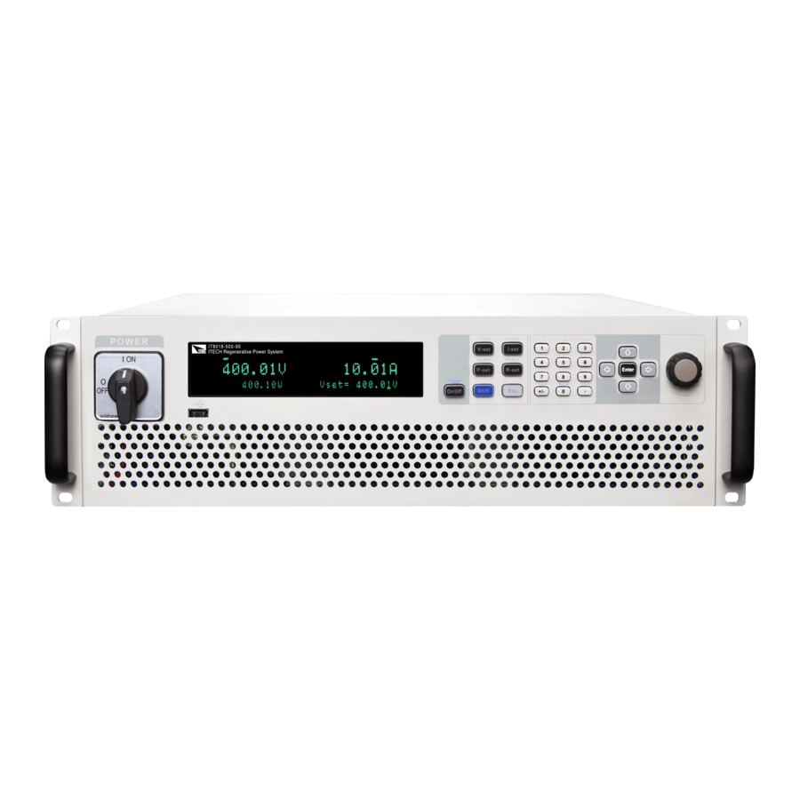
1.2 Front-Panel Overview For the IT8000 series Regenerative DC Electronic Load, all front panels of the 3U model are the same, and the operation panels of other models are the same as those of the 3U model. The following is the front panel schematic of the 3U model. -
Page 15: Keyboard Introduction
Quick Reference 1.3 Keyboard Introduction The keyboard introduction of IT8000 series Regenerative DC Electronic Load is shown as follows. Keys Description [On/Off] Turn the load input on or off. When lit, indicates that the input is enabled or on. [V-set]... -
Page 16: Push-On Knob
Save the common parameter settings. (Save) 1.4 Push-on Knob The IT8000 series Regenerative DC Electronic Load provides a knob on the front panel as shown in the next figure. The functions of the posh-on knob is described as follows. •... -
Page 17: Rear Panel Introduction
After completing the value setting or selecting a menu item, pushing the knob acts like pressing [Enter] key to confirm the operation. 1.5 Rear Panel Introduction The rear panel of the 3U model of the IT8000 series Regenerative DC Elec- tronic Load (after removing the protective cover) is shown below. 3U Models 1. - Page 18 The rear panel of the 6U model is the same as the 3U model. Other models (15U, 27U cabinets) have the same rear panel terminals except for the cabinet size. The following takes a 15U cabinet as an example. Copyright © Itech Electronic Co., Ltd.
-
Page 19: Vfd Indicator Lamps Description
10. AC power input terminals (L1, L2, L3, and PE) 11. Cabinet earthing rod 1.6 VFD Indicator Lamps Description The IT8000 series Regenerative DC Electronic Load VFD indicator lamps de- scription is as follows: Copyright © Itech Electronic Co., Ltd. -
Page 20: Configuration Menu Function
1.7 Configuration Menu Function This section gives an overview of the configuration menu of the IT8000 series load. The procedures to operate the configuration menu are as follows. 1. Press the composite keys [Shift]+[V-set] (Config) on the front panel to enter the configuration menu. - Page 21 Set the delay time to turn off the input. I-Rise Slope Set the current rising time. I-Fall Slope Set the current falling time. Set Von function Latch Latch mode Level=0.00V Set the Von value Living Living mode Level=0.00V Set the Von value Copyright © Itech Electronic Co., Ltd.
-
Page 22: System Menu Function
1.8 System Menu Function This Chapter offers a general introduction of system menus, allowing users to have a preliminary understanding of system functions of this IT8000 series. The steps of the system menu function are as follows: 1. Press the composite keys [Shift]+[P-set] (System) on the front panel to en- ter the system menu. - Page 23 Gateway: 0.0.0.0 DNS1: 0.0.0.0 DNS2: 0.0.0.0 MAC: 8C:C8:F4:40:01:E1 MDNS Status: HostName: HostDesc: Domain: TCPIP:INSTR Socket Port: 30000 Configure LAN IP information. IP-Conf Configure LAN IP mode. IP-Mode Auto: automatically configure the address of the instrument. Copyright © Itech Electronic Co., Ltd.
- Page 24 MDNS: MDNS service state. • • PING: PING service state. • • Telnet-scpi: telnet-scpi service state. • • Web: Web service state. • • VX-11: VX-11 service state. • • Raw-socket: Raw-socket serv- ice state. • Copyright © Itech Electronic Co., Ltd.
- Page 25 When re-entering DigPort, the interface can display the changed option. For detailed introduction of menus and functions, see 5.11 Digital I/O Function (Digital Port). IO-1. Ps-Clear, Not- Function setting of pin 1 Invert Copyright © Itech Electronic Co., Ltd.
-
Page 26: Options Introduction
Screen displays loading time. Turn the display on. Turn the display off. 1.9 Options Introduction The IT8000 series Regenerative DC Electronic Load supports the following two types of optional accessories (sold separately), the details are as below: • Communication interface card –... - Page 27 The fiber optic module and cable are the necessary accessories for the parallel connection. Different numbers of fiber optic modules and cables are used in different numbers of parallels. Copyright © Itech Electronic Co., Ltd.
- Page 28 Quick Reference The installation positions of optical modules in different parallel scenarios are different. For details, 1.5 Rear Panel Introduction. Copyright © Itech Electronic Co., Ltd.
-
Page 29: Inspection And Installation
Connecting the Power Cord. USB communication This accessory is se- cable lected when the USB in- terface is used for starting up remote operation. It contains User Manual, Programming Guide and other user documentations. Copyright © Itech Electronic Co., Ltd. -
Page 30: Instrument Size Introduction
2.2 Instrument Size Introduction The instrument should be installed at well-ventilated and rational-sized space. Please select appropriate space for installation based on the instrument size. The detailed dimension drawings of the IT8000 series are as follows: Copyright © Itech Electronic Co., Ltd. - Page 31 Inspection and Installation 3U Models Copyright © Itech Electronic Co., Ltd.
- Page 32 Inspection and Installation 6U Models Copyright © Itech Electronic Co., Ltd.
- Page 33 Inspection and Installation 15U Models Copyright © Itech Electronic Co., Ltd.
-
Page 34: Connecting The Power Cord
The 15U and 27U cabinets only show the size data. The number of instru- ments installed in the cabinet should be based on the actual model. 2.3 Connecting the Power Cord Precautions To prevent electric shock and damage to the instrument, observe the following precautions. Copyright © Itech Electronic Co., Ltd. - Page 35 L1, L2 and L3 terminals of power input on the rear panel of the in- strument; the yellow-green wire is grounding wire, which is connected to the PE terminal of power input on the rear panel. Copyright © Itech Electronic Co., Ltd.
- Page 36 The yellow-green wire is grounding wire, which is connected to the pro- tective grounding terminal (PE). 5. Mount the protective cover back to its original position. 6. Connect the other end of the power cable to the required AC distribution box. Copyright © Itech Electronic Co., Ltd.
-
Page 37: Connecting The Device Under Test (Dut)
2.4 Connecting the Device Under Test (DUT) This section describes how to connect the test cables between the instrument and DUT. Precautions To prevent electric shock and damage to the instrument, observe the following precautions. Copyright © Itech Electronic Co., Ltd. - Page 38 • Always use test cables provided by ITECH to connect the equipment. If test cables from other factories are used, please confirm the maximum current that the test cables can withstand.
- Page 39 The connection diagram and steps of remote measurement are as follows: Copyright © Itech Electronic Co., Ltd.
- Page 40 Never touch cables or connections immediately after turning off the in- strument at the end of the test. Lethal voltages may remain at the input terminals after turn-off. Verify that there is no dangerous voltage on the input or sense terminals before touching them. Copyright © Itech Electronic Co., Ltd.
-
Page 41: Remote Interface Connection
• VCP: Virtual serial port. Select this type, you need to install the correspond- ing driver. Please contact ITECH Technical Support for the driver. • LAN: USB-LAN interface, which is a virtual network port. After selecting this option, you also need to set the communication parame- ters of the LAN, and the menu items are the same as those in the LAN menu. -
Page 42: Lan Interface
1. Press the composite keys [Shift]+[P-set] (System) on the front panel to en- ter the system menu. 2. Rotate the knob or press the Up/Down key to select I/O and press [Enter]. Copyright © Itech Electronic Co., Ltd. - Page 43 1.8 System Menu Function for details. Configure LAN Interface Information The configurable parameters of the IT8000 series load are described as follows. IP-Conf • IP: This value is the Internet Protocol (IP) address of the instrument. An IP address is required for all IP and TCP/IP communications with the instru- ment.
- Page 44 – Off: Indicates that the service is disabled. 2.5.2.1 Using Web Server The instrument has a built-in Web server for monitoring and controlling the in- strument via a Web browser in PC. To use the Web server, connect the Copyright © Itech Electronic Co., Ltd.
- Page 45 LAN configuration parameters; • Web Control: Enables the Web control to begin controlling the instrument. This page allows you to monitor and control the instrument; • LAN Configuration: Reconfigure the LAN parameters; Copyright © Itech Electronic Co., Ltd.
-
Page 46: Can Interface
Inspection and Installation • Manual: Go to the ITECH official website and view or download the relevant documents. • Upload: Performs a system upgrade. Click CONNECT to connect the PC with the instrument, then click Select File to select the system upgrade installation package (for example, itech_6000_P.itech), and then click UPLOAD performs the upgrade op-... - Page 47 2. Rotate the knob or press the Up/Down key to select I/O and press [Enter]. 3. Press the Left/Right key to select CAN and press [Enter]. 4. Set the baud rate, address and other parameters, press [Enter]. Copyright © Itech Electronic Co., Ltd.
-
Page 48: Gpib Interface (Optional)
6. Press the Left/Right key to select GPIB and press [Enter]. 7. Press the numeric keys to set the GPIB address and press [Enter]. 2.5.5 RS–232 Interface (Optional) The RS-232 interface shares the same communication card (IT-E167) with the analog function. Copyright © Itech Electronic Co., Ltd. - Page 49 5. Rotate the knob or press the Up/Down key to select I/O and press [Enter]. 6. Press the Left/Right key to select RS232 and press [Enter]. 7. Set the relevant communication parameters in turn, and press [Enter]. The RS–232 interface parameters are as follows. Copyright © Itech Electronic Co., Ltd.
- Page 50 Make sure the correct cable and adapter are connected. Note that internal wiring may not be correct even if the cable has a suitable plug; • The cable must be connected to the correct serial ports (COM1, COM2, etc) of PC. Copyright © Itech Electronic Co., Ltd.
-
Page 51: Getting Started
When you turn the POWER switch on for the first time after purchase, the instru- ment starts with its factory default settings. Each time thereafter, the instrument starts according to the setting that you selected as outlined in 5.6 Set the Power-on State (PowerOn). Copyright © Itech Electronic Co., Ltd. - Page 52 Removing the power cord will disconnect AC input power to the unit. Power Switch Introduction User can adjust the power switch directly to turn on or turn off the instrument. The status of Power switch is as follows. Copyright © Itech Electronic Co., Ltd.
- Page 53 (CC mode) and input voltage, current, power and other information. If an error occurs during the self-test, an error message is displayed. The follow- ing table lists the error messages you might see. Copyright © Itech Electronic Co., Ltd.
-
Page 54: Set Input Value
2.3 Connecting the Power Cord to select proper AC input. 4. If you need additional assistance, contact ITECH technical support engineer. 3.2 Set Input Value The voltage value, current value, power value and resistance value can all be programmed. -
Page 55: Use The Front Panel Menu
When the number in front of the menu item is blinking, indicates this item is selected currently. Press [Enter] key to enter the selected menu item and press [Esc] to exit the menu. Copyright © Itech Electronic Co., Ltd. -
Page 56: On/Off Control
If the [On/Off] key light is on, indicates that the input is turned on. If the [On/Off] key light is off, indicates that the input is turned off.When the load input is on, the operating status flag (CV/CC/CW/CR) on the VFD will be illuminated. Copyright © Itech Electronic Co., Ltd. -
Page 57: Load Function
2. Press [Enter] key to enter into the parameter setting interface. 3. Press the Left / Right key or turn the knob to adjust the value of this parameter. 4. After the parameter settings are complete, press [Enter]. Copyright © Itech Electronic Co., Ltd. -
Page 58: Basic Operation Mode
Load Function 4.1.2 Basic Operation Mode The IT8000 series electronic loads operate in constant voltage, current, resist- ance, or power modes to satisfy a wide range of test requirements. • Constant Current Operation Mode (CC) Under CC mode, the electronic load will consume constant current in regard- less of whether the input voltage changes or not, as shown in the following figure. -
Page 59: Complex Operation Mode
When the voltage rises to exceed the set constant resistance for sinking, it will switch to CR mode for sinking. The CV+CR mode can be applied to the LED simulation and test the LED power supply to get the LED current ripple parameters. Copyright © Itech Electronic Co., Ltd. - Page 60 CW modes. It is suitable for lithium ion battery charger testing to get a com- plete V-I charging curve. Moreover, the auto mode can avoid damaging the UUT when the protection circuit is damaged. Copyright © Itech Electronic Co., Ltd.
-
Page 61: Set The Input-On/Input-Off Delay Time (On Delay/Off Delay
2. Use knob or up and down keys to select I-Rise Slope or I-Fall Slope and press [Enter] to confirm. 3. Use knob or the number keys to adjust the input-on/input-off delay time and press [Enter] to confirm. Copyright © Itech Electronic Co., Ltd. -
Page 62: Short-Circuit Analog Function
When VON LIVING function is started, the load starts load test only when the power voltage rises and is higher than Von Point loading voltage. When the power voltage drops and is lower than Von Point unloading voltage, the load will unload. Copyright © Itech Electronic Co., Ltd. - Page 63 Von Point loading voltage. When the power voltage drops and is lower than Von Point unloading voltage, the load will unload. The procedures to set Von function are as follows. Copyright © Itech Electronic Co., Ltd.
-
Page 64: Advanced Feature
4.2 Advanced Feature 4.2.1 LIST Function The IT8000 series load supports a total of 10 List files (List01 to List10), each of which can be set up to 200 steps. You need to edit the voltage/current value, slope and time width of each step, or you can set repeat times (1 to 65535) for each List file. - Page 65 TX and RX of the fiber to realize List synchronization triggering between multiple units. None Turn off (default) Tout Turn on Save to Save the edited List program. group Copyright © Itech Electronic Co., Ltd.
- Page 66 The procedures are as follows: 1. Insert the USB flash drive into the front panel USB connector. 2. Press the composite keys [Shift]+[I-set] (Function) on the front panel to en- ter the function menu. Copyright © Itech Electronic Co., Ltd.
- Page 67 Supports exporting the internal List file to an external USB flash drive. The ex- ported List file is saved in .csv format. 1. Insert the USB flash drive into the front panel USB connector. Copyright © Itech Electronic Co., Ltd.
- Page 68 8. Based on the selected trigger method, perform the trigger operation. Take the manual trigger as an example. Press [Shift]+[On/Off](Trigger) on the front panel to run the selected List file. For details about the List trigger method, see 5.8 Select Trigger Source (Trig Source). Copyright © Itech Electronic Co., Ltd.
-
Page 69: Battery Discharging Test Function
4.2.2 Battery Discharging Test Function The IT8000 series load provides the battery discharging test function, which is suitable for discharging tests on all types of portable batteries. The user can set three cut off conditions: cut off voltage, current off capacity and the charging time. -
Page 70: Protection Function
Press [Shift]+[R-set] (Protect) to enter Protect menu interface. The descrip- tions of protect menu are listed in the table below. Protect Protection function menu Overcurrent protection Turn the OCP function off. Turn the OCP function on. Level OCP limit Copyright © Itech Electronic Co., Ltd. - Page 71 When the instrument enters the protection state, the buzzer sounds (if Beep menu item is set as default state On), the VFD status indicators Prot and Off are lit, and [On/Off] is turned off. Copyright © Itech Electronic Co., Ltd.
-
Page 72: Set Over-Current Protection (Ocp)
OCP state. Possible Cause Many reasons can cause OCP, the details are as follows: • The set protection limit Level is lower than the current Meter value. Copyright © Itech Electronic Co., Ltd. -
Page 73: Set Over-Power Protection (Opp)
3. Press the left/right key or rotate the knob to select On and press [Enter] to enter the setting interface. 4. Set the protection limit Level and the delay time Delay in sequence, and press [Enter] to confirm. Copyright © Itech Electronic Co., Ltd. -
Page 74: Set Under-Voltage Protection (Uvp)
Even with proper ventilation, the instrument can over- heat in the following situations. • If the ambient temperature is too high. • If you use the instrument to test for long periods. Copyright © Itech Electronic Co., Ltd. -
Page 75: Sense Reverse Protection
When you return power to the instrument, verify that the cooling fan is running. If not, please contact ITECH Technical Support. Leaving the instrument powered on with an inoperative cooling fan may result in damage to the instrument. -
Page 76: Basic Operation
All panel keys, except the [On/Off] and [Shift]+[3] (Local) keys, are locked. – You can press [Shift]+[3] (Local) to switch the remote control to local control. The mode modification will not affect the input parameters of the load. Copyright © Itech Electronic Co., Ltd. -
Page 77: Key Lock Function
AUTO mode: Vs, Is, Ps and Rs Config Menu Operation mode I-Rise Slope I-Fall Slope Von function mode and level You can do the save and recall operations by the following two methods. Copyright © Itech Electronic Co., Ltd. -
Page 78: Save Operation
3. Press [Enter] to recall the parameters. 5.4 Data Logging Function The IT8000 series Regenerative DC Electronic Load supports the recording and saving of test data. This Chapter introduces how to use this function in details. The user can select the following data sources for recording: •... - Page 79 • Max/Min: If this option is se- lected, it means the maximum value and minimum value of data acquired in the data recording pe- riod as indicated in the data sav- ing table. Copyright © Itech Electronic Co., Ltd.
- Page 80 *TRG, a trigger operation is performed. • External Connect to pin 4 of the digital I/O interface (P-IO) and set pin 4 to Ext-Trig→- Trig-In→Dlog to trigger. For details, see 5.11.4 IO–4. Ext-Trig, Not-Invert. Copyright © Itech Electronic Co., Ltd.
-
Page 81: Set The Beeper Status (Beep)
5.6 Set the Power-on State (PowerOn) This menu item is used to control the settings and input state when the load is powered on. The detailed power-on parameters and input state are as follows. Copyright © Itech Electronic Co., Ltd. - Page 82 Rs ance value of the instrument Voltage setting under CVCC Rated voltage of the mode: Vs instrument Current setting under CVCC mode: Is Voltage setting under CVCR Rated voltage of the mode: Vs instrument Copyright © Itech Electronic Co., Ltd.
- Page 83 Last+Off: Indicates when powered on, the instrument will remain the same settings as last time you powered off the instrument, but the input status is Off. 4. After the parameter settings are complete, press [Enter]. Copyright © Itech Electronic Co., Ltd.
-
Page 84: Sense Function (Sense)
On: Indicates turn the sense function on. 4. After the parameter settings are complete, press [Enter]. 5.8 Select Trigger Source (Trig Source) For the IT8000 series load, the List and data logging functions can be triggered for running by the following methods: •... -
Page 85: Set The Communication Information (I/O Con)
5.9 Set the Communication Information (I/O Con) This menu item is used to set the communication information between instru- ment and PC. The standard communication interfaces for IT8000 series load are USB, LAN, CAN and VCP. You can also select the non-standard interface GPIB or RS-232 based on personal requirement. -
Page 86: Set Parallel Operation Mode (Parallel)
The IT8000 series load supports multiple instruments to work in parallel mode to provide more power and current input capability. Parallel instruments can ac- tively average current. - Page 87 1. Ensure that the power switches of the three units and the main switch of the AC power distribution box are off. 2. Refer Figure 5–1 Wiring connection diagram to connect three units. Figure 5–1 Wiring connection diagram Copyright © Itech Electronic Co., Ltd.
- Page 88 3. Remove the cables connection of the System Bus and DC input terminals between three units. 4. Power on the three instruments separately. After the instrument is restarted, the VFD shows that the instrument is work- ing in single mode. Copyright © Itech Electronic Co., Ltd.
-
Page 89: Digital I/O Function (Digital Port)
Basic Operation 5.11 Digital I/O Function (Digital Port) The IT8000 series load supports digital I/O function. The user can realize logic control over high and low level input or output by related configurations in the system menu, namely general digital signal I/O function. In addition to general digital I/O functions, this series can be customized to meet different special needs through different pin wirings. - Page 90 Living, Not-Invert menu item. For parameter introduction, see 5.11.5 IO–5. INH-Living, Not-Invert. Corresponds to the function set in the Pulse signal Level or PWM System→Digital Port→IO–6. Sync- signal On, Not-Invert menu item. For Copyright © Itech Electronic Co., Ltd.
- Page 91 Output→PWM, the user needs to set the frequency (PWM Freq) and du- ty cycle (PWM Duty) values. For example, if the PWM Freq is set to 100Hz and the PWM Duty is set to 10%, the output waveform is as follows: Copyright © Itech Electronic Co., Ltd.
-
Page 92: Io-1. Ps-Clear, Not-Invert
Indicates whether to invert the input/output Invert pulse or level signal. • Invert: Yes Invert • Not-Invert: No This default function means that when Clear the instrument generates protection, the protection state can be cleared via this pin. Copyright © Itech Electronic Co., Ltd. - Page 93 Pulse input: When the instrument is under protection, the instrument will clear protection after receiving the pulse signal from external input. 1. Refer to the figure below to connect pin 1 to the external oscilloscope. Copyright © Itech Electronic Co., Ltd.
-
Page 94: Io-2. Ps, Not-Invert
5.11.2 IO–2. Ps, Not-Invert Parameter Description IO–2. Ps, Not- Parameter setting for pin 2. Invert Not- Indicates whether to invert the input/output Invert pulse or level signal. • Invert: Yes Invert • Not-Invert: No Copyright © Itech Electronic Co., Ltd. - Page 95 2 outputs high level; when the instrument is under protection, pin 2 outputs low level. When pin 2 is set to Invert, the output level is completely opposite. 1. Refer to the figure below to connect pin 2 to the external oscilloscope. Copyright © Itech Electronic Co., Ltd.
-
Page 96: Io-3. Off-Status, Not-Invert
Pin 3 receives the level signal from the outside. Output Pin 3 sends the digital signal (1, 0, PWM) to the outside. True By default (Not-Invert), the out- put digital signal is 1 (i.e. low Copyright © Itech Electronic Co., Ltd. - Page 97 1. Refer to the figure below to connect pin 3 to the external oscilloscope. 2. Confirm that pin 3 function is set to the default option, namely IO-3. Off-Status, Not-Invert. 3. Turn on [On/Off]. 4. Check the oscilloscope and confirm that pin 3 outputs low level. Copyright © Itech Electronic Co., Ltd.
-
Page 98: Io-4. Ext-Trig, Not-Invert
This function needs to be triggered at the upper com- puter side through SCPI in- struction. For de- tails, refer to instructions re- lated to ACQuire in the Trigger subsystem of the Instruction Manual. Copyright © Itech Electronic Co., Ltd. - Page 99 Taking the triggering of List function as an example, the text below will introduce how to use pin 4’s default function Ext-Trig. • Trig–Out 1. Refer to the figure below to connect pin 4 to the external oscilloscope. Copyright © Itech Electronic Co., Ltd.
- Page 100 5. Check the oscilloscope and confirm whether pin 4 has following pulse signal output. Level rise slope 10us Level fall slope Minimum time width 30us for low level keep • Trig-In 1. Refer to the figure below to connect pin 4 to the external oscilloscope. Copyright © Itech Electronic Co., Ltd.
-
Page 101: Io-5. Inh-Living, Not-Invert
List file is running or not. 5.11.5 IO–5. INH-Living, Not-Invert Parameter Description IO–5. Living, Parameter setting for pin 5. Not-Invert Not- Indicates whether to invert the input/output pulse or Invert level signal. • Invert: Yes Invert • Not-Invert: No Copyright © Itech Electronic Co., Ltd. - Page 102 The [On/Off] button light is lighted on and VFD still displays On, but the actual input is 0; when pin 5 receives high level sig- nal again, the input state is recovered. Copyright © Itech Electronic Co., Ltd.
- Page 103 The param- eter requirements of this pulse signal are as follows: Level rise slope 10us Level fall slope Minimum time width 30us for low level keep Copyright © Itech Electronic Co., Ltd.
-
Page 104: Io-6. Sync-On, Not-Invert
When the protection state is cleared, manually turn on [On/Off] again. 5.11.6 IO–6. Sync-On, Not-Invert Parameter Description IO–6. Sync- Parameter setting for pin 6. On, Not- Invert Not- Indicates whether to invert the input/output pulse or Invert level signal. Copyright © Itech Electronic Co., Ltd. - Page 105 The parameter requirements of this pulse signal are as follows: Level rise slope 10us Level fall slope Minimum time width 30us for low level keep The bi-direction I/O functions are introduced as below: Copyright © Itech Electronic Co., Ltd.
-
Page 106: Io-7. Sync-Off, Not-Invert
B’s input function is synchronously turned on. 5.11.7 IO–7. Sync-Off, Not-Invert Parameter Description IO–7. Sync-Off, Parameter setting for pin 7. Not-Invert Not- Indicates whether to invert the input/output pulse Invert or level signal. Copyright © Itech Electronic Co., Ltd. - Page 107 The parameter requirements of this pulse signal are as follows: Level rise slope 10us Level fall slope Minimum time width 30us for low level keep The bi-direction I/O functions are introduced as below: Copyright © Itech Electronic Co., Ltd.
-
Page 108: Analogue Function (Ext-Program) (Optional)
The external analog quantity function is not the standard-equipped function for the instrument. It is only avail- able when the user selects the IT-E167 interface card. Copyright © Itech Electronic Co., Ltd. - Page 109 Do not connect any ground wire of the analog interface to the positive and negative terminals of the input interface. Analog Card Interface Introduction The analog function interface is located on the optional IT-E167. The pins de- scription is as below. Copyright © Itech Electronic Co., Ltd.
- Page 110 1V, it is low level. When the input voltage is ≥ 3V, it is high level. Set the load mode with the input voltage and level combination of the Input2: For detailed mode definition, refer to Input2 description. Copyright © Itech Electronic Co., Ltd.
- Page 111 When the analog quantity control function of this series of instrument is used, the user needs to set the conversion relationship of the analog quantity ex- pected value based on requirements. The analog quantity values in each mode Copyright © Itech Electronic Co., Ltd.
- Page 112 The voltage control in CV mode is taken as an example below to describe the connection and usage. 1. Refer to the figure below to complete the pin connection. Copyright © Itech Electronic Co., Ltd.
- Page 113 4. The connection method is as shown below. The voltage reading from -10 to 10V corresponds to the zero to full-scale voltage/current setting of the instrument. The connection diagram is as shown below. Copyright © Itech Electronic Co., Ltd.
-
Page 114: Restored To Factory Setting (System Reset)
Table 5–3 Initial value of the parameter Parameter Initial Value Category Main Voltage setting under CV mode: Rated voltage of the interface instrument Current setting under CC mode: Power setting under CW mode: Copyright © Itech Electronic Co., Ltd. - Page 115 Resistance setting under AUTO Rated maximum resist- mode: Rs ance value of the instrument On/Off state System Beep menu PowerOn Reset Sense ListTrig Source Manual DataLogger Trig Source Manual USB-VCP • Digital Port IO–1: Ps-Clear Copyright © Itech Electronic Co., Ltd.
-
Page 116: View The System Information (System Info)
This menu item is used to view the system information of the instrument. The procedures to view the system information are as follows. 1. Press the composite keys [Shift]+[P-set] (System) on the front panel to en- ter the system menu. Copyright © Itech Electronic Co., Ltd. -
Page 117: Observe Power Grid Information (Ac-Meter)
The regenerative power value can be observed on the front panel , including voltage, frequency and power, as well as total power, total current regenerative and total historical regenerative power. The procedures to view the power grid information are as follows. Copyright © Itech Electronic Co., Ltd. -
Page 118: Display Loading Time (Disp On Timer)
Off: indicates the beeper is off. 4. After the parameter settings are complete, press [Enter]. 5.17 System Upgrade The IT8000 series load supports the upgrade of the system version. System up- grade includes the following two methods: • During the start-up period after the instrument is powered on, through the USB interface on the front panel, select the system upgrading files in the memory device (USB flash drive) for upgrading. - Page 119 For example, when there are multiple system upgrading package post- fixed with .itech in the root directory of your USB flash drive, you need to use a text editing tool to open the configuration file and specify the up- grade package name corresponding to the present upgrade operation.
- Page 120 2. Power on the instrument. At this point, press Shift for several times till the instrument can detect the system upgrading files in the USB flash drive. After the system upgrading files are detected, the interface displays as follows: Update Select(xx/yy) SN: ALL Copyright © Itech Electronic Co., Ltd.
- Page 121 The system will automatically perform upgrading. If No is selected, it means to exit upgrading, and the system will di- rectly enter into the main interface. 5. After the upgrading is completed, you need to restart the instrument manually. Copyright © Itech Electronic Co., Ltd.
-
Page 122: Technical Specification
This chapter will introduce the main technical parameters of this load , such as rated voltage/current/power and so on. Besides, we will introduce the working environment and storage temperature. ♦ Main Specification ♦ Supplemental Characteristics 6.1 Main Specification Copyright © Itech Electronic Co., Ltd. -
Page 123: It8006-500-30
≤0.01% + 50mV Coefficient (%of Output/℃+Offset) Current ≤0.02% + 6mA Read Back Temper- Voltage ≤0.01% + 50mV ature Coefficient (% of Output/℃ Current ≤0.02% + 6mA +Offset) Rising slope 30A/ms Dynamic Falling slope 30A/ms Copyright © Itech Electronic Co., Ltd. - Page 124 Time Storage -10℃~70℃ temperature OVP, OCP, OPP, OTP and Vsense reversed protection Protective function Communication Standard: USB、CAN、LAN,optional: GPIB、RS232 interface Isolation (output to 750V ground) Working 0~40℃ temperature Dimension (mm) 483W*801.61D*151.3H Weight( net) 28KG Copyright © Itech Electronic Co., Ltd.
-
Page 125: It8012-500-60
Voltage ≤0.01% + 50mV Coefficient (%of Output/℃+Offset) Current ≤0.02% + 12mA Read Back Temper- Voltage ≤0.01% + 50mV ature Coefficient (% of Output/℃+Offset) Current ≤0.02% + 12mA Rising slope 60A/ms Dynamic Falling slope 60A/ms Copyright © Itech Electronic Co., Ltd. - Page 126 Time Storage -10℃~70℃ temperature OVP, OCP, OPP, OTP and Vsense reversed protection Protective function Communication Standard: USB、CAN、LAN,optional: GPIB、RS232 interface Isolation (output to 750V ground) Working 0~40℃ temperature Dimension (mm) 483W*801.61D*151.3H Weight( net) 34KG Copyright © Itech Electronic Co., Ltd.
-
Page 127: It8018-500-90
Voltage ≤0.01% + 50mV Coefficient (%of Output/℃+Offset) Current ≤0.02% + 18mA Read Back Temper- Voltage ≤0.01% + 50mV ature Coefficient (% Current ≤0.02% + 18mA of Output/℃+Offset) Rising slope 90A/ms Dynamic Falling slope 90A/ms Copyright © Itech Electronic Co., Ltd. - Page 128 Time Storage -10℃~70℃ temperature OVP, OCP, OPP, OTP and Vsense reversed protection Protective function Communication Standard: USB、CAN、LAN,optional: GPIB、RS232 interface Isolation (output to 750V ground) Working 0~40℃ temperature Dimension (mm) 483W*801.61D*151.3H Weight( net) 40KG Copyright © Itech Electronic Co., Ltd.
-
Page 129: It8018-1500-30
≤0.01% + 150mV Coefficient (%of Output/℃+Offset) Current ≤0.02% + 6mA Read Back Temper- Voltage ≤0.01% + 150mV ature Coefficient (% Current ≤0.02% + 6mA of Output/℃+Offset) Rising slope 30A/ms Falling slope 30A/ms Dynamic Dynamic 500Hz Frequency Copyright © Itech Electronic Co., Ltd. - Page 130 Time Storage -10℃~70℃ temperature OVP, OCP, OPP, OTP and Vsense reversed protection Protective function Communication Standard: USB、CAN、LAN,optional: GPIB、RS232 interface Isolation (output to 2000V ground) Working 0~40℃ temperature Dimension (mm) 483W*801.61D*151.3H Weight( net) 40KG Copyright © Itech Electronic Co., Ltd.
-
Page 131: Supplemental Characteristics
Technical Specification 6.2 Supplemental Characteristics State storage capacity: 10 sets Recommended calibration frequency: once a year Cooling style: fans Copyright © Itech Electronic Co., Ltd. -
Page 132: A Appendix
♦ Fuse Replacement A.1 Specifications of Red and Black Test Lines ITECH provides you with optional red and black test lines, which are sold indi- vidually and you can select for test. For specifications of ITECH test lines and maximum current values, refer to the table below. -
Page 133: Fuse Replacement
If there are no fuse assembly on the instrument rear panel, it means that you can’t replace the fuse by yourself. Please contact the ITECH engineer on the condition of the same malfunction. - Page 134 2. Have a visual inspection of the fuse to see whether it is burnt out; if yes, replace it with another fuse of the same specification. Re- fer to the corresponding technical specifi- cations for fuse rating. Copyright © Itech Electronic Co., Ltd.
- Page 135 3. Please replace with a fuse of the same specification. Refer to the technical specifi- cation of the corresponding instrument. 4. When install, put into the fuse box firstly. Then Push and turn the fuse box to 90 de- grees clockwise. Copyright © Itech Electronic Co., Ltd.
- Page 136 Contact Us Thanks for purchasing ITECH products. In case of any doubts, please con- tact us as follows: 1. Refer to accompanying data disk and relevant manual. 2. Visit ITECH website: www.itechate.com. 3. Select the most convenient contact method, for further information.
Need help?
Do you have a question about the IT8000 Series and is the answer not in the manual?
Questions and answers