Table of Contents
Advertisement
Quick Links
Advertisement
Table of Contents

Related Manuals for HikRobot ID5000 Series


Summary of Contents for HikRobot ID5000 Series
- Page 1 ID5000 Series Smart Code Reader User Manual...
- Page 2 INTERRUPTION, OR LOSS OF DATA, CORRUPTION OF SYSTEMS, OR LOSS OF DOCUMENTATION, WHETHER BASED ON BREACH OF CONTRACT, TORT (INCLUDING NEGLIGENCE), PRODUCT LIABILITY, OR OTHERWISE, IN CONNECTION WITH THE USE OF THE PRODUCT, EVEN IF HIKROBOT HAS BEEN ADVISED OF THE POSSIBILITY OF SUCH DAMAGES OR LOSS.
- Page 3 ID5000 Series Smart Code Reader User Manual THE PERFORMANCE DATA IN THIS PUBLICATION IS BASED ON HIKROBOT'S INTERNAL RESEARCH/EVALUATION. ACTUAL DATA MAY VARY DEPENDING ON SPECIFIC CONFIGURATIONS AND OPERATING CONDITIONS AND HIKROBOT SHALL NOT BEAR THE CONSEQUENCES ARISING THEREFROM. IN THE EVENT OF ANY CONFLICTS BETWEEN THIS MANUAL AND THE APPLICABLE LAW, THE LATER PREVAILS.
- Page 4 Note important points of the main text. Available Model This manual is applicable to the ID5000 Series Smart Code Reader. Safety Instruction These instructions are intended to ensure that the user can use the product correctly to avoid danger or property loss.
- Page 5 ID5000 Series Smart Code Reader User Manual Power Supply ● When wiring or dismounting, make sure that the device power is cut off, and do not operate under electrification. ● Avoid contact with exposed circuit. When the device is powered on, avoid contact with exposed junctions and parts.
- Page 6 ID5000 Series Smart Code Reader User Manual ● Put electrostatic sensitive components into anti-static bags for protection. ● It is suggested to place humidifier in dry environment to maintain suitable humidity and reduce static electricity generation. Maintenance ● If the product is not working properly, contact the store or the nearest service center. Do not disassemble or modify the device in any way.
-
Page 7: Table Of Contents
ID5000 Series Smart Code Reader User Manual Contents Chapter 1 Appearance ......................... 1 Chapter 2 Interface and Indicator ....................... 4 2.1 12-Pin Interface ........................4 2.2 Indicator Status ........................5 Chapter 3 I/O Wiring ........................... 6 3.1 Input Signal ..........................6 3.2 Output Signal ......................... - Page 8 ID5000 Series Smart Code Reader User Manual 8.1.7 Set Self-Adaptive Adjustment.................. 33 8.1.8 Set Mirror X ......................34 8.1.9 Set Test Pattern ......................35 8.2 Code Algorithm Settings...................... 35 8.2.1 Add Code........................35 8.2.2 Set Code Reading ROI ....................36 8.2.3 Set 1D Algorithm Parameter ..................
- Page 9 ID5000 Series Smart Code Reader User Manual 8.8.6 Profinet ........................78 8.8.7 MELSEC........................79 8.8.8 Ethernet/IP ....................... 80 8.8.9 ModBus ........................80 8.8.10 Fins .......................... 81 8.8.11 SLMP ........................83 8.9 User Set Customization ....................... 84 8.10 Statistics Information ......................85 8.11 Event Report ........................
-
Page 10: Chapter 1 Appearance
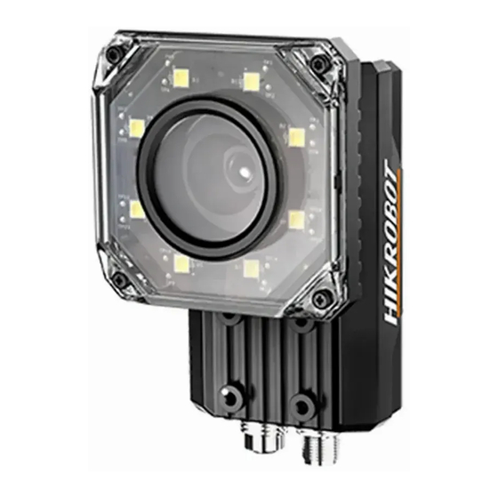
ID5000 Series Smart Code Reader User Manual Chapter 1 Appearance Note Appearance here is for reference only. Refer to the device's specification for detailed dimension information. Figure 1-1 Appearance (Type I) Figure 1-2 Appearance (Type II) - Page 11 ID5000 Series Smart Code Reader User Manual Figure 1-3 Appearance (Type III) Table 1-1 Component Description Name Description It can be replaced with other lens cap. Transparent and polarization lens Lens Cap cap are optional. It is used to fix the device to installation position. It is recommended to Screw Hole use M4 screw.
- Page 12 ID5000 Series Smart Code Reader User Manual Name Description It is the power indicator. The indicator is solid blue when the device PWR Indicator operates normally. It is network connection indicator. The indicator is solid green when the LNK Indicator network transmission is normal.
-
Page 13: Chapter 2 Interface And Indicator
ID5000 Series Smart Code Reader User Manual Chapter 2 Interface and Indicator 2.1 12-Pin Interface Read the following section to get definitions of 12-pin interface. Figure 2-1 12-Pin Interface Table 2-1 Pin Definitions Signal I/O Signal Source Description Color DC-PWR... -
Page 14: Indicator Status
ID5000 Series Smart Code Reader User Manual Note You should refer to the table above and the label attached to the power and I/O cable to wire the device. 2.2 Indicator Status Read the following section to get the indicator status of the device. -
Page 15: Chapter 3 I/O Wiring
ID5000 Series Smart Code Reader User Manual Chapter 3 I/O Wiring 3.1 Input Signal The device's LineIn 0/1/2 is opto-isolated input, and their internal circuit is as follows. Note ● The input voltage ranges from 5 VDC to 30 VDC. -
Page 16: Output Signal
ID5000 Series Smart Code Reader User Manual Table 3-1 Input Electrical Feature Parameter Name Parameter Symbol Value Input Logic Level Low 1.5 VDC Input Logic Level High 2 VDC Input Falling Delay 81.6 μs Input Rising Delay 7 μs 3.2 Output Signal The device's LineOut 0/1/2 is opto-isolated output, and their internal circuit is as follows. -
Page 17: Input Signal Wiring
ID5000 Series Smart Code Reader User Manual Table 3-2 Output Electrical Feature Parameter Name Parameter Symbol Value Output Logic Level Low 730 mV Output Logic Level High 3.2 VDC Output Falling Delay 6.3 μs Output Rising Delay 68 μs Output Falling Time 3 μs... -
Page 18: Output Signal Wiring
ID5000 Series Smart Code Reader User Manual Device Power Input Signal NPN Device Power Ground Device Opto-Isolated Input Signal Line Device Power Ground NPN Power Ground GND of PWR GND of VCC Figure 3-6 Input Signal Connecting to NPN Device without Pull-Up Resistor If the VCC of NPN device is 12 VDC or 24 VDC and 1 KΩ... - Page 19 ID5000 Series Smart Code Reader User Manual PNP Device PNP Device Power Device Power Opto-Isolated Signal Line Output Device Output Signal Ground PNP Power Ground Device Power Ground GND of VCC GND of PWR Figure 3-8 Output Signal Connecting to PNP Device...
-
Page 20: Serial Port
ID5000 Series Smart Code Reader User Manual 3.5 RS-232 Serial Port The device supports output via RS-232 serial port. The 9-pin male connector and 25-pin male connector are commonly used serial ports, as shown below. You can refer to the table below for the specific pin name and function. -
Page 21: Chapter 4 Installation
ID5000 Series Smart Code Reader User Manual Chapter 4 Installation 4.1 Installation Preparation You need to prepare following accessories before installation. Table 4-1 Accessories Name Quantity Description It refers to the 3-meter 12-pin power and I/O cable, and is Power and I/O Cable 1 included in the package. - Page 22 ID5000 Series Smart Code Reader User Manual Steps 1. Use M4 screw to fix the device to fixed bracket. 2. Select one of installation methods, and install the device to the installation position. Figure 4-1 Rear Installation Figure 4-2 Front Installation 3.
- Page 23 ID5000 Series Smart Code Reader User Manual Figure 4-3 Gigabit Ethernet Interface Wiring 4. Use power and I/O cable to connect the device to a DC switch power supply. Figure 4-4 Power and I/O Wiring...
-
Page 24: Chapter 5 Device Connection
ID5000 Series Smart Code Reader User Manual Chapter 5 Device Connection Device connection to the client software is required for device’s configuration and remote operations. This section introduces how to install the client software, set PC network, connect the device to the client software, etc. -
Page 25: Turn Off Firewall
ID5000 Series Smart Code Reader User Manual 5.2 Turn off Firewall To ensure stable client running and image transmission, you are recommended turning off Windows firewall before using the client software. Steps Note For different Windows versions, the path name or interface may differ. Please refer to the actual condition. -
Page 26: Set Device Network
ID5000 Series Smart Code Reader User Manual Figure 5-3 Set PC Network 3. Set NIC property. 1) Go to NIC settings page: Control Panel → Hardware and Sound → Device Manager → Network Adapter. 2) Select corresponding network interface card, and click Advanced. -
Page 27: Connect Device To Client Software
ID5000 Series Smart Code Reader User Manual Figure 5-4 Modify IP Address 6. Click OK. 5.5 Connect Device to Client Software Make sure that your device IP address is in the same network segment with the PC where you installed the client software before connecting the device to it. -
Page 28: Chapter 6 Client Software Layout
ID5000 Series Smart Code Reader User Manual Chapter 6 Client Software Layout After connecting to the device, the client software can read the device information and display it. Figure 6-1 Main Window Note The specific interfaces of the client software may differ by its versions. - Page 29 ID5000 Series Smart Code Reader User Manual You can set device parameters in device configuration area. Figure 6-2 Device Configuration Area Table 6-2 Configuration Area Description Module Name Description You can connect or disconnect device, modify device IP Device Connection address, view device information, etc.
-
Page 30: Chapter 7 Device Mode Settings
ID5000 Series Smart Code Reader User Manual Chapter 7 Device Mode Settings The device supports 3 types of operating modes, including Test, Normal, and Raw. You can select different modes in live view window according to actual demands. Note ● Stopping the real-time acquisition is required before selecting modes. - Page 31 ID5000 Series Smart Code Reader User Manual Figure 7-2 Code Reading...
-
Page 32: Chapter 8 Device Settings
ID5000 Series Smart Code Reader User Manual Chapter 8 Device Settings You are recommended to complete device settings in following order: Device Connection → Image Settings → Algorithm Settings → I/O Control Settings → Data Processing → Communication Settings → Configuration Management. - Page 33 ID5000 Series Smart Code Reader User Manual Note ● Make sure you have select the device to be set in Device Connection before setting image parameters. ● For specific parameter range like exposure time, gain and acquisition frame rate, refer to the device’s specification for details.
-
Page 34: Set Exposure
ID5000 Series Smart Code Reader User Manual Figure 8-1 Set Image 8.1.2 Set Exposure The device supports four types of exposure modes, including off, once, continuous, and alternate. Refer to the table below for details. Table 8-1 Exposure Mode Exposure Mode... -
Page 35: Set Gain
ID5000 Series Smart Code Reader User Manual Figure 8-2 Once or Continuous Exposure Alternate Exposure Steps 1. Right click the device in Device Connection, and click Feature Tree. 2. Go to Image Setting, and enable Exposure Alternate. 3. Select one exposure parameter from Exposure Index. - Page 36 ID5000 Series Smart Code Reader User Manual Table 8-2 Gain Mode Gain Mode Description The device adjust gain according to the value configured by the user in Gain (dB). The device adjusts gain automatically according to the image brightness. After Once adjusting once, the device will switch to off mode.
-
Page 37: Set Polling
ID5000 Series Smart Code Reader User Manual 8.1.4 Set Polling The polling function allows the device to acquire images based on the parameters you set, including exposure time, gain, Gamma, and light source. Currently, 2 types of polling modes are available, including single mode and multiple mode. - Page 38 ID5000 Series Smart Code Reader User Manual are enabled, the polling order is Param3 > Param1 > Param2 > Param4 > Param5. Steps 1. Go to Image Settings → Image → Polling Enable, and select Multiple as Polling Enable. 2. Set Polling Time and Polling Period according to actual demands.
-
Page 39: Set Light Source
ID5000 Series Smart Code Reader User Manual 8.1.5 Set Light Source You can select different light types, and set their related parameters in the light interface. Note ● Light source parameters may differ by device models. ● Make sure you have selected the device to be set in Device Connection before setting light source parameters. - Page 40 ID5000 Series Smart Code Reader User Manual at a specific interval during code reading, and Flash Long means the light is solid during code reading. Lighting Duration It sets the lighting duration and the unit is μs. Lighting Delay Time Note This parameter is available only when you set Flash Strobe as the Light Mode.
-
Page 41: Set Lens Focus
ID5000 Series Smart Code Reader User Manual Line Out Delay Time It sets the delay time for lighting after device outputs event source, and the unit is μs. Line Out Ahead Time It sets how earlier the external light starts lighting before the device outputs event source information, and the unit is μs. -
Page 42: Set Self-Adaptive Adjustment
ID5000 Series Smart Code Reader User Manual Manual Focus 1. Go to Image Settings → Auto Focus, and set Focus Step according to actual demands. 2. Click in Adjust Focus to adjust focus. 3. Select the position parameter from Focus Position, and click Execute in Focus Position Save to save the focus position. -
Page 43: Set Mirror X
ID5000 Series Smart Code Reader User Manual 4. (Optional) Enable or disable Lighting Adapt during self-adaptive adjustment. If it is enabled, the client software will select the best one from all lighting options during the self-adaptive adjustment. If it is disabled, the client software will keep the lighting status before the self-adaptive adjustment. -
Page 44: Set Test Pattern
ID5000 Series Smart Code Reader User Manual 8.1.9 Set Test Pattern Test pattern helps troubleshooting image problems and images in the test pattern are only for test. When exceptions occur in images acquired by the device in real time, you can check if images in the test pattern have similar problems to determine the cause of an exception. -
Page 45: Set Code Reading Roi
ID5000 Series Smart Code Reader User Manual Figure 8-13 Add Codes 8.2.2 Set Code Reading ROI Algorithm ROI (Region of Interest) allows the device to execute algorithms and read codes on the specific area you selected, and thus improving code reading efficiency. - Page 46 ID5000 Series Smart Code Reader User Manual Draw Single Group of ROI Steps 1. Go to Algorithm Settings, click All Features, and find Algorithm ROI. 2. Click Draw to draw ROI in the live view window. 3. (Optional) Repeat the above step to draw multiple ROIs according to actual demands.
- Page 47 ID5000 Series Smart Code Reader User Manual 4. Repeat other optional steps mentioned in drawing single group of ROI according to actual demands. 5. (Optional) Enable ROI Link IO Enable in Algorithm Control, and there will be prompts by the output device when codes are not read in any ROI.
- Page 48 ID5000 Series Smart Code Reader User Manual Figure 8-15 Create Chessboard ROI 3. Click after creating ROI, and the red frame becomes green as shown below. Figure 8-16 Draw ROI via Chessboard 4. (Optional) Click to restore the ROI to the full screen, and click to clean all configured ROIs.
-
Page 49: Set 1D Algorithm Parameter
ID5000 Series Smart Code Reader User Manual 8.2.3 Set 1D Algorithm Parameter Click All Features on the upper-right to display all algorithm parameters. In the Algorithm Parameter page, select 1DCode as Arithmetic Type, and then you can set its corresponding parameters. - Page 50 ID5000 Series Smart Code Reader User Manual parameters. Note ● You should have selected at least one type of 2D code. ● For different models of the device, the specific parameters may differ, and the actual device you purchased shall prevail.
- Page 51 ID5000 Series Smart Code Reader User Manual Figure 8-17 White QR Code Figure 8-18 Black QR Code ● For DM code, the code color is determined by the color of its "L" shaped sides. White "L" shaped sides indicate that the code color is white, and black "L" shaped sides indicate that the code color is black.
-
Page 52: Set 2D Code Quality Evaluation
ID5000 Series Smart Code Reader User Manual continuous. Usually the continuous code uses squares as the minimum units. Discrete stands for the minimum units in the "L" shaped sides of the DM code are discrete, or the minimum units in the concentric square like in the QR code are discrete. -
Page 53: Set Code Score
ID5000 Series Smart Code Reader User Manual Steps 1. Set Sym Proc Type according to actual demands, and the default type is Type 1. Type 1 has a strong capacity to locate codes. 2. Set Iso Edition, including Iso15415 and Iso29158 ●... -
Page 54: Signal Input Settings
ID5000 Series Smart Code Reader User Manual ● The code score is determined by two factors including image quality and print quality of codes. The range of code score is between 0 and 100, and the higher the score, and easier the code can be read. -
Page 55: Enable Internal Trigger Mode
ID5000 Series Smart Code Reader User Manual mode. Internal Trigger Mode In this mode, the device acquires images via its internal signals. External Trigger Mode In this mode, the device acquires images via external signals like software signal and hardware signal. - Page 56 ID5000 Series Smart Code Reader User Manual Figure 8-24 Set and Execute Software Trigger Mode Steps 1. Click I/O Control Settings → Input → Trigger Mode. 2. Select On as Trigger Mode. 3. Select the specific line as Trigger Source according to actual demands.
- Page 57 ID5000 Series Smart Code Reader User Manual 3. Select Counter 0 as Trigger Source. 4. Set Trigger Delay, Count Number, Count Source and Line Out Trigger In Polarity according to actual demands. Figure 8-26 Set and Execute Counter Trigger Mode Set and Execute TCP Trigger Mode TCP start specifies the TCP server as the source for the trigger signal.
- Page 58 ID5000 Series Smart Code Reader User Manual the specified string text, the trigger signal will be outputted. Steps 1. Click I/O Control Settings → Input → Trigger Mode. 2. Select On as Trigger Mode. 3. Select UDP Start as Trigger Source.
- Page 59 ID5000 Series Smart Code Reader User Manual Figure 8-29 Set and Execute Serial Port Trigger Mode Set and Execute Self Trigger Mode Self trigger mode allows you to trigger the device according to the trigger period you configured. Steps 1. Click I/O Control Settings → Input → Trigger Mode.
-
Page 60: Stop Trigger
ID5000 Series Smart Code Reader User Manual 8.3.4 Stop Trigger Stop trigger settings configure the source and condition to stop trigger. You can stop device trigger via TCP, UDP, I/O and serial port. TCP Stop Trigger When the TCP server receives the specified string text, the trigger will be stopped. - Page 61 ID5000 Series Smart Code Reader User Manual You can set Rising Edge or Falling Edge as Stop Trigger In Polarity to stop trigger when selecting physical line as IO Stop Trigger Selector. Figure 8-33 IO Stop Trigger When selecting Software Trigger End as IO Stop Trigger Selector, you can click Execute in Software Stop Trigger to stop current trigger.
- Page 62 ID5000 Series Smart Code Reader User Manual Figure 8-35 Serial Stop Trigger Stop Trigger via Timeout Duration Note TimeOut Stop Trigger Enable is only available when the device mode is set to Normal and the Trigger Mode is On. When the trigger time reaches the specified maximum value (in ms), the trigger will be stopped.
-
Page 63: Signal Output Settings
ID5000 Series Smart Code Reader User Manual Stop Trigger via Code Number Note CodeNum Stop Trigger Enable is only available when the device mode is set to Normal and the Trigger Mode is On. This function means that the code quantity outputted by the device is restricted to the settings you configured here. -
Page 64: Enable Line Inverter
ID5000 Series Smart Code Reader User Manual Figure 8-38 Select Output Signal 8.4.2 Enable Line Inverter The level inverter function allows the device to invert the electrical signal level of an I/O line, and meets requirements of different devices for high or low electrical signal level. - Page 65 ID5000 Series Smart Code Reader User Manual Acquisition Start Active If acquisition starts, the output signal will be triggered. Acquisition Stop Active If acquisition stops, the output signal will be triggered. Frame Burst Start Active If the burst of a frame starts, the output signal will be triggered.
- Page 66 ID5000 Series Smart Code Reader User Manual Figure 8-40 Set Event Source Select Acquisition Start Active If you select Acquisition Start Active as Line Out Activation Event, you can set its output delay time and duration. Line Out Delay Time It sets the delay time for outputting the output signal.
- Page 67 ID5000 Series Smart Code Reader User Manual Select Acquisition Stop Active If you select Acquisition Stop Active as Line Out Activation Event, you can set its output delay time and duration. Line Out Delay Time It sets the delay time for outputting the output signal.
- Page 68 ID5000 Series Smart Code Reader User Manual Select Frame Burst Stop Active If you select Frame Burst Stop Active as Line Out Activation Event, you can set its output delay time and duration. Line Out Delay Time It sets the delay time for outputting the output signal.
- Page 69 ID5000 Series Smart Code Reader User Manual Select Soft Trigger Active If you select Soft Trigger Active as Line Out Activation Event, you can set its output delay time, duration, and execute outputting signal manually. Line Out Delay Time It sets the delay time for outputting the output signal.
- Page 70 ID5000 Series Smart Code Reader User Manual Figure 8-47 Select Hard Trigger Active Select Counter Active If you select Counter Active as Line Out Activation Event, you can set its output delay time and duration. Line Out Delay Time It sets the delay time for outputting the output signal.
- Page 71 ID5000 Series Smart Code Reader User Manual Line Out Period It sets the time period of the output signal. Figure 8-49 Select Timer Active Select No Code Read If you select No Code Read as Line Out Activation Event, you can set its output delay time and duration.
- Page 72 ID5000 Series Smart Code Reader User Manual Line Out Duration It sets the time duration of the output signal. Figure 8-51 Select Read Success Select Light Strobe Long If you select Light Strobe Long as Line Out Activation Event, you do not need to set any parameters.
-
Page 73: Indicator Customization
ID5000 Series Smart Code Reader User Manual Select Compare Fail If you select Compare Fail as Line Out Activation Event, you can set its output delay time and duration. Line Out Delay Time It sets the delay time for outputting the output signal. -
Page 74: Code Reading Result Settings
ID5000 Series Smart Code Reader User Manual Parameters Description LineOut 1 The indicators flash once when LineOut 1 outputs signals. LineOut 2 The indicators flash once when LineOut 2 outputs signals. Figure 8-54 Indicator Customization 8.6 Code Reading Result Settings In Data Processing module, you can set filter rules for reading barcodes and other data processing related parameters. - Page 75 ID5000 Series Smart Code Reader User Manual Filter Mode. Note The filter rule parameters may differ with different device modes and trigger modes. Normal Filter Mode When the device mode is Normal, Trigger Mode is On, and Filter Mode is Normal, you can set the following parameters according to actual demands.
- Page 76 ID5000 Series Smart Code Reader User Manual valid value is from 1 to 256. For example, if you set the value as 6, the device will not parse the contents of the barcodes which contain less than 6 characters. Max. Code Length If the length of a barcode is longer ((in terms of the number of characters contained in the barcode) than the configured value, the device will not parse the contents of the barcode.
-
Page 77: Set Result Format
ID5000 Series Smart Code Reader User Manual If the length of a barcode is shorter (in terms of the number of characters contained in the barcode) than the configured value, the device will not parse the contents of the barcode. The valid value is from 1 to 256. - Page 78 ID5000 Series Smart Code Reader User Manual ● For details about communication protocol, see section Communication Settings for details. ● The specific parameter names and values may differ by device firmware versions. Result Output via Smart SDK When the communication protocol is Smart SDK, device mode is Normal and trigger mode is On, you can set following parameters.
- Page 79 ID5000 Series Smart Code Reader User Manual It sets the picture saving method. Four methods are available, including recently frame, all frames, range frames and specific frame. If specific frame is selected as Local Save Picture Strategy, you need to set Local Picture Index.
- Page 80 ID5000 Series Smart Code Reader User Manual It selects a format type from the drop-down list for the time stamp contained in the file name. Take YYYYMMDD_HHMMSSFFF as an example, (from the left to the right) YYYY represents year, MM represents month, DD represents date, HH represents hour, MM represents minute, SS represents second, and FFF represents millisecond.
- Page 81 ID5000 Series Smart Code Reader User Manual It sets the FTP picture saving method when no code is read. Four methods are available, including recently frame, all frames, range frames and specific frame. If specific frame is selected as FTP Save Picture Strategy, you need to set FTP Picture Index.
- Page 82 ID5000 Series Smart Code Reader User Manual Strategy. Local Picture Name Content It selects what contents you want to display in file name, including frame time, trigge r No. and frame No. Local Time Format It selects a format type from the drop-down list for the time stamp contained in the file name.
-
Page 83: Contrast Control Settings
ID5000 Series Smart Code Reader User Manual not meet the min. length requirement. It includes Off, Add Noread, and Just Noread. Off does not add contents and the device outputs code recognized only. Add Noread allows you to add contents to the min. length requirement and output. Just Noread means that the device outputs Noread only if the code recognized by the device does not meet the min. - Page 84 ID5000 Series Smart Code Reader User Manual Figure 8-56 Regular Contrast Consecutive Number Contrast The consecutive number contrast requires you to set consecutive code rules, and the client software will contrast the data that the device reads with preset rules and outputs contrast result.
-
Page 85: Communication Settings
ID5000 Series Smart Code Reader User Manual Figure 8-57 Consecutive Number Contrast 8.8 Communication Settings The communication protocol is used to transmit and output code reading result and image. The communication protocol is related to the device modes. With various device modes, the device supports different communication protocols and corresponding parameters. -
Page 86: Tcp Client
ID5000 Series Smart Code Reader User Manual Figure 8-58 Smart SDK 8.8.2 TCP Client The TCP includes TCP Server and TCP Client. If TCP Client is selected as the Communication Protocols, you can enable TCP Protocol, and enter TCP Dst Addr and TCP Dst Port. -
Page 87: Serial
ID5000 Series Smart Code Reader User Manual 8.8.4 Serial If Serial is selected as the Communication Protocols, you can enable Serial Protocol, enter Serial Baud Rate, Serial Data Bits, Serial Parity, and Serial Stop Bits. Figure 8-61 Serial 8.8.5 FTP If FTP is selected as the Communication Protocols, you can enable FTP Protocol, enter FTP Host Addr, FTP Host Port, FTP User Name, and FTP User PWD. -
Page 88: Melsec
ID5000 Series Smart Code Reader User Manual Figure 8-63 Profinet 8.8.7 MELSEC If MELSEC is selected as the Communication Protocols, you can enable MELSEC Protocol Enable and set related parameters according to actual demands. MELSEC Destination Address It sets the IP address of the target PLC. -
Page 89: Ethernet/Ip
ID5000 Series Smart Code Reader User Manual Figure 8-64 MELSEC 8.8.8 Ethernet/IP If Ethernet/IP is selected as the Communication Protocols, you can enable Ethernet/IP Enable, and the device will output data via Ethernet/IP. Figure 8-65 Ethernet/IP 8.8.9 ModBus If ModBus is selected as the Communication Protocols, you can enable ModBus Enable and set related parameters according to actual demands. -
Page 90: Fins
ID5000 Series Smart Code Reader User Manual ModBus Control Address Offset It refers to the address offset, and is 0 by default. ModBus Control Data Number It is 2 by default. ModBus State Address Space It is input_register by default. - Page 91 ID5000 Series Smart Code Reader User Manual parameters according to actual demands. Fins Communication Mode It includes UDP or TCP. Fins Local Port It is 9600 by default. Fins Dst IP It sets the IP address of the target device.
-
Page 92: Slmp
ID5000 Series Smart Code Reader User Manual Figure 8-67 Fins 8.8.11 SLMP If SLMP is selected as the Communication Protocols, you can enable SLMP Enable and set related parameters according to actual demands. SLMP Dst Addr It sets the IP address of the target PLC. -
Page 93: User Set Customization
ID5000 Series Smart Code Reader User Manual SLMP Module Station Num It displays the module station number. SLMP Timeout It sets the waiting time before the returning of PLC’s response. Figure 8-68 SLMP 8.9 User Set Customization The Configuration Management module allows you to set and manage the user set. A user set is a group of parameter values with all the settings needed to control the device, and you can save, load and switch different user sets. -
Page 94: Statistics Information
ID5000 Series Smart Code Reader User Manual Note The Default refers to restore the device parameter settings to the factory ones. Start Settings The selected user set will be automatically loaded after the device being powered on. For example, if you select Default, the device parameter settings will be restored to the factory settings. -
Page 95: Event Report
ID5000 Series Smart Code Reader User Manual Parameter Name Description Algo Time Ave. The average time of algorithm, and the unit is ms. Algo Time Max. The max. time of algorithm, and the unit is ms. Algo Time Min. The min. time of algorithm, and the unit is ms. - Page 96 ID5000 Series Smart Code Reader User Manual Figure 8-71 Event Report...
-
Page 97: Chapter 9 Device Operation
ID5000 Series Smart Code Reader User Manual Chapter 9 Device Operation The device operation section introduces some basic device operations about how to start live view, acquisition and recording, add cross line in the image, split window, view reports, etc. -
Page 98: Add Cross Line
ID5000 Series Smart Code Reader User Manual Figure 9-2 Enable Acquisition 9.3 Add Cross Line During live view, you can add a cross line on the live view image to adjust the position of the object in the view. Click... -
Page 99: Split Window
ID5000 Series Smart Code Reader User Manual Figure 9-4 Start Recording 9.5 Split Window The client software supports window division function that allows you to split the window into multiple-window mode to view the live view of multiple devices at the same time. -
Page 100: View Log
ID5000 Series Smart Code Reader User Manual 9.7 View Log You can view the device logs and export them to the local PC. Click in control toolbar to open the device log window, and you can view different types of logs, including device errors, warning, and informational log, etc. -
Page 101: Enable Device Auto Work
ID5000 Series Smart Code Reader User Manual Figure 9-8 Set NTP Timing 9.9 Enable Device Auto Work This function allows the device to automatically enter the operating status after being powered You can go to Config Management → Device Auto Work Enable, and enable Device Auto Work Enable. -
Page 102: Chapter 10 Device Maintenance
ID5000 Series Smart Code Reader User Manual Chapter 10 Device Maintenance 10.1 Update Firmware The device supports updating firmware via the client software. Note ● Disconnect the device with client software. ● Please use the firmware package of the corresponding device model for upgrading. - Page 103 ID5000 Series Smart Code Reader User Manual Figure 10-2 Reboot Device...
-
Page 104: Chapter 11 Faq (Frequently Asked Question)
ID5000 Series Smart Code Reader User Manual Chapter 11 FAQ (Frequently Asked Question) 11.1 Why the image is very dark? Problem All black or too dark during preview. Reason Too small adjustment value of exposure and gain, or the lens aperture is not opened enough. -
Page 105: Why There Is No Image In The Live View
ID5000 Series Smart Code Reader User Manual Solution ● Check the device power connection (observe whether the PWR light is solid blue or not), to make sure the device is powered up normally. ● Check the network connection (observe whether the LNK light is solid green or not and ACT light is flashing yellow or not) to make sure the device can be connected to the network normally. -
Page 106: Chapter 12 Revision History
ID5000 Series Smart Code Reader User Manual Chapter 12 Revision History Table 12-1 Revision History Version No. Document No. Date Revision Details ● Modify section Set Code Reading ROI. ● Modify section Set 1D Algorithm Parameter. V2.5.0 UD27157B Feb. 9, 2022 ●... - Page 107 UD27157B...
Need help?
Do you have a question about the ID5000 Series and is the answer not in the manual?
Questions and answers