
Subscribe to Our Youtube Channel
Related Manuals for ETC Vortek NXT


Summary of Contents for ETC Vortek NXT
- Page 1 Vortek NXT Hoist CE User Operations Manual Part Number: 8070M2000 Rev: D Released: 2019-05...
- Page 2 T h e r e p r o d u c t i o n , t r a n s m i s s i o n o r u s e o f t h i s d o c u me nt , o r i t s c o n t e n t s i s n o t p e r m it t e d u n l e s s a u t h o r i z e d i n w r i t i n g .
-
Page 3: Table Of Contents
Chapter 3 3.1 Contacting ETC ......6 Vortek Hoist ......7 Chapter 4 4.1 Intended Use. - Page 4 10.1 Troubleshooting Vortek Hoist ....44 10.2 System Messages......44 Vortek NXT Hoist User Operations Manual...
- Page 5 Chapter 13 13.1 Vortek NXT Technical Data ....52 13.1.1 Emission Sound Pressure Level ....53 13.1.2 Product Dimensions &...
-
Page 6: Acronyms And Definition Of Terms
• Control System - ETC control equipment associated with the operation of the hoist or hoist system. • Hazard - Potential source of harm. -
Page 7: Safety And Warnings
Chapter 2 Safety and Warnings 2.1 Document Conventions This document uses the following conventions to draw your attention to important information. Note: Notes are helpful hints and information that is supplemental to the main text. CAUTION: A Caution statement indicates situations where there may be undefined or unwanted consequences of an action, potential for data loss or an equipment problem. - Page 8 Do not exceed point load, Uniform Distributed Load (UDL), or Working Load Limit (WLL) or Hoist Capacity for any line set. ETC hoists must only be used to move a maximum load equal to or less than the capacity of your specific hoist.
- Page 9 WARNING: Machinery installation, maintenance and disposal must be performed by competent or qualified persons. WARNING: At the end of machinery installation, commissioning must be performed by a qualified person. WARNING: The load carrying device (e.g., batten) installed on the wire rope cable must conform to DIN 56950-1:2012 and CWA 15902-1:2008 and the relevant documentation must be provided by the installer.
-
Page 10: Hoist Capacity
The limits are not the same for all line sets, so be sure to check the Working Load Limit for all line sets in your system. NEVER exceed the working load limit or the Hoist Capacity for any line set. Vortek NXT Hoist User Operations Manual... -
Page 11: Overview
If you are having difficulties, your most convenient resources are the references given in this user manual. To search more widely, try the ETC Web site at etcconnect.com. If none of these resources are sufficient, contact ETC Technical Services directly at one of the offices identified below. Emergency service is available from all ETC offices outside of normal business hours. -
Page 12: Vortek Hoist
Vortek Hoist 4.1 Intended Use A Vortek NXT hoist is a fixed- or variable-speed electric wire rope winch designed for use in the entertainment and event industry (theatres, multi-purpose halls, exhibition halls, television and radio studios, concert halls, schools and other rooms for shows and events). -
Page 13: Technical Description
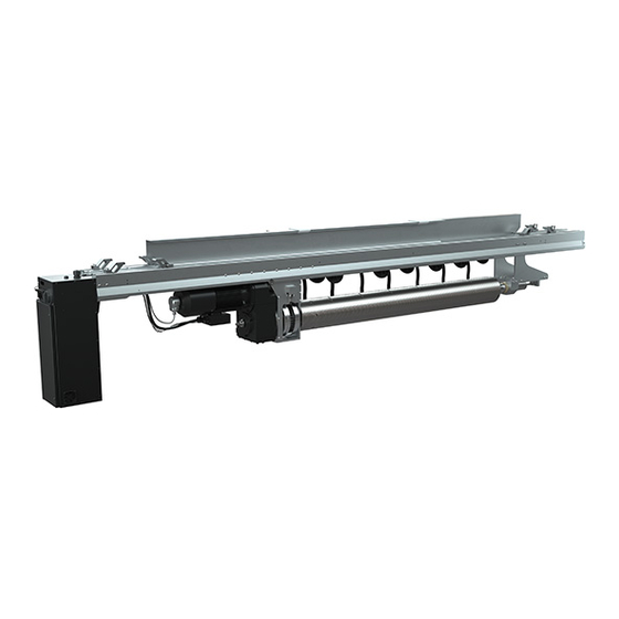
Vortek hoists, controlled by Foundation, QuickTouch, or QuickTouch+ controls. A Vortek NXT hoist is a fixed- or variable-speed electric wire rope winch, designed for use in the entertainment and event industry. Figure 1: Vortek NXT front view 7.3 Basic Hoist Components... -
Page 14: Incoming Goods, Transport And Storage
[Figure 4] 104 cm (41") long, a maximum of 22 cm (8-1/2”) wide and 5 cm (2") thick to use this location. Figure 4: Lifting by Motor End position Vortek NXT Hoist User Operations Manual... - Page 15 Insert the forks completely into the slot. Raise the forks and the rack to lift the crate. The second lifting point is from the side [Figure 5] Note: When using this location, spread the forks as wide as possible; either side can be used to lift the crates.
-
Page 16: General Information For Storage
The layout, nameplate, and label on the side of the crate identify the model number and placement within the installation. Once out of the crate, Vortek NXT hoists are virtually indistinguishable from each other except for the label on bottom of the Motor Control Box (MCB) -
Page 17: Installation
Chapter 7 Installation 7.1 General Information on Installation 7.1.1 Vortek NXT Hoist Installation Tool List A non-metric tool set is required for the Vortek CE hoist installation. • 9/16" Combination Wrench • 3/4" Combination Wrench • 3/8" Drive 7/16" Socket •... -
Page 18: Uncrating Vortek Hoist
7.3 Basic Hoist Components Backbone Backbone Motor End Tail End Clamps Stiffeners Beam Clamps Beam Clamps Cables Out End Motor Tail End Motor End Cable Drop Tail End Motor Cable Drop Control Figure 9: Basic Hoist Components Vortek NXT Hoist User Operations Manual... -
Page 19: Attaching Backbone Stiffeners
Figure 10: Basic Hoist Components – covers removed 7.4 Attaching Backbone Stiffeners All Vortek NXT hoist installations require the use of aluminum backbone stiffeners installed on top of the hoist backbone with two 3/8" threaded rods, four nuts and two steel backbone clamps. - Page 20 Place a backbone clamp onto a single side and slide it 15.2 cm (6") past the end of the second channel. Repeat for the other end of the stiffeners with the second clamp [Figure 13] CAUTION: Do not tighten the set screw on these backbone clamps at this time. Vortek NXT Hoist User Operations Manual...
- Page 21 Figure 13: Backbone clamp on backbone stiffener Installation...
-
Page 22: Mounting Vortek Hoist
WARNING: Risk of personal injury and/or damage to the hoist. Do not lift the Vortek NXT hoist using methods other than the ETC's hoist lifting clips. Hoist lifting clips install into the hoist backbone and connect the hoist to the lifting cables. -
Page 23: Hoist Placement
7.5.2 Hoist Placement Motor End hoist beam clamps are secured at the first position and cannot be adjusted. You must align the Motor End of the hoist with the corresponding edge of the beam flange. This can be accomplished by using a laser level to distinguish between the leading edge of the I-beam and the Motor End beam clamp. -
Page 24: Lift Hoist To I-Beams
With the hoist lifting clips securely in place on the hoist backbone, lift the hoist out the skid approximately 7.6 cm (3"). Check that all connections are secure at the hoist lifting clips. CAUTION: Make sure that the cables do not get caught on anything as the hoist is raised. Vortek NXT Hoist User Operations Manual... - Page 25 When lifting the hoist to the level of the I-beams, stop just short so that the beam clamps can be adjusted for the spacing of the I-beams [Figure 17] Figure 17: Positioning motor end beam clamps Raise the hoist into position so the backbone is about 12.7 mm (1/2") below the I-beams and start tightening the clamps using the 9/16"...
- Page 26 Repeat for the Tail End set of beam clamps. Tighten all four 5/16 x 18 socket head screws on the two Tail End sliding beam clamps to 13.5 Nm (10 ft/lb) [Figure 19] Figure 19: Tighten beam clamps to the backbone Vortek NXT Hoist User Operations Manual...
-
Page 27: Installation Of Loft Blocks
Tighten the set screws on the backbone stiffener clamps. Torque the screws to 13.5 Nm (10 ft/ lb). 13.5 Nm Figure 20: Tighten backbone stiffener clamp screws 7.5.4 Installation of Loft Blocks Note: Loft blocks and other wire rope routing accessories are provided by the installer. Requirements are: •... -
Page 28: Routing Lift Lines
7.5.5 Routing Lift Lines Note: Each Vortek NXT project has a detailed set of job drawings which determine the installation location of each hoist and the related equipment. Refer to these drawings for system layout, lift line layout, and location. -
Page 29: Electrical Installation
WARNING: Confirm the number of crimps required for the Nicopress sleeve by reviewing the Nicopress crimp tool manual. 7.6 Electrical Installation Installation of electrical components can be performed by a competent person, but the installation needs to be supervised by a qualified person. 7.6.1 Mains Connection WARNING: Do not connect the Vortek hoist electrical connection to any power supply... -
Page 30: Qt1-C Field Service Kit Connection
7.6.2 QT1-C Field Service Kit Connection The QT1-C Field Service Kit allows for local control, hoist movement, and service of the Vortek NXT Figure 22 hoist [ Figure 22: QT1-C Field Service Kit An international power supply kit has been provided for connection of the QT1-C Field Service Kit to a power source. -
Page 31: Vertical Mounting
32 7.7 Vertical Mounting The standard mounting method of a Vortek NXT hoist is to be hung from the structural steel in a horizontal position. The previous sections detailed this method of mounting the hoist. If you are planning to mount the hoist vertically, the following procedure provides some guidelines for you to follow. - Page 32 Terminate both of these shackles to a single lifting shackle. With an appropriately sized lifting device, slowly lift the hoist from its crate until it is roughly 1.2 m (4’-0") above the floor. Clear the area of the crate and packaging. Vortek NXT Hoist User Operations Manual...
- Page 33 Thread the supplied lifting ring in to the hole on the tail end of the hoist backbone as shown and terminate the end of a second lifting device to the lifting ring. 1.2 m (4’-0”) Figure 27 Incrementally raise the tail end lifting device while lowering the centered lifting device to change the orientation of the hoist from horizontal to vertical.
- Page 34 Tail End sliding beam clamps to 13.5 Nm (10 ft/lb). Remove the tail end lifting device and the lifting ring. For information on installing loft blocks, refer 7.5.4 Installation of Loft Blocks page 22 Figure 30 Vortek NXT Hoist User Operations Manual...
-
Page 35: Operation
Chapter 8 Operation Stand-alone operation of the Vortek NXT hoist is through the use of the supplied QT1-C Field Service Kit. For information on the use of Foundation or QuickTouch family controllers, please reference the related User Operations Manuals. Before performing any service and maintenance on the hoist or its... -
Page 36: Set Motor Control Box Address
WARNING: RISK OF DEATH OR SEVERE INJURY. DO NOT interfere or use the hoist limit switches or limit switch override buttons located near the three address switches. These switches are for use by ETC trained/authorized personnel only! Figure 32 Confirm address dials are set to address 0 0 1 [ Figure 32: Motor Control Box address dials and limits Replace the secured access panel. -
Page 37: Power On
A start-up screen is shown as the system powers up. This screen displays contact information for the installer responsible for the system or ETC’s website and phone number. Your installer may have chosen to display their contact information. The software version is also displayed during the start up. -
Page 38: Testing And Resetting E-Stop System
Note: You will not be able to move the hoist until power has been cycled Note: Test the E-stop system prior to each use of the Vortek hoist, or at least once a day. Vortek NXT Hoist User Operations Manual... -
Page 39: Start Movement With Qt1-C Field Service Kit
The hoist will stop moving if the hoist produces a fault or error code. 8.7 Hoist Commissioning Requirements When the Vortek NXT hoist is installed, and before use, hard travel limits, commissioning soft limits, position offset and weight offset must be performed by an ETC trained/authorized installer. - Page 40 8.7.1.1 Overtravel Limits Overtravel limits are set at the ETC factory as a relative measurement [approximately 15 cm (6 in)] to the upper and lower limits set by the installer. In other words, upper overtravel will be set at roughly 15 cm above the upper limit.
- Page 41 8.7.1.2 Setting and Testing Upper Limits WARNING: Setting and testing limits is a procedure reserved for ETC trained/authorized personnel only! Using the QTC-1 Field Service Kit, move the batten up until it is at the desired upper overtravel limit. CAUTION: The Overtravel limit should be no less than 15 cm (6 in) from the bottom of the loft block to the top of the attachment for the batten.
- Page 42 8.7.1.3 Setting and Testing Lower Limits WARNING: Setting and testing limits is a procedure reserved for ETC trained/authorized personnel only! Using the QTC-1 Field Service Kit, move the batten down until it is at the desired lower overtravel limit. CAUTION: The Overtravel limit should be no less than 15 cm (6 in) from the bottom of the load to the top of the nearest point of conflict.
-
Page 43: Advanced Operations With Qt1-C
8.8 Advanced Operations with QT1-C 8.8.1 Position Presets Presets are pre programmed stopping points. Each hoist can have one preset recorded. When a moving hoist reaches a preset position it stops movement. If the up [ ] or down [ ] button is released and pressed again, the hoist will continue movement past the preset position. - Page 44 The current load monitoring state will be displayed on the LCD. Turn the keyswitch back to [RUN]. Remove the key from the keyswitch or connect the QT1-C Field Service Kit to the next hoist and repeat the Quick Learn process. Vortek NXT Hoist User Operations Manual...
- Page 45 Effects of Load Monitoring When load monitoring is enabled, and the monitored load is heavier than recorded, upward movement of the hoist will be disabled, and an error message displays on the QT1-C Field Service Kit stating “Load Too Heavy”. Downward motion is still permitted.
-
Page 46: Remote Control
CAUTION: To be operated by ETC trained/authorized personnel only. Once unplugged, the E-stop button on the remote will be inactive. For this reason, the remote control must be stored in an inaccessible space (not visible to people) when not connected to the system. -
Page 47: Connecting Remote Control
9.1 Connecting Remote Control The wired end of the remote terminates at a male 7 pin XLR connector. Attach this connector to its female counterpart, labeled Remote, located in the QT1-C Field Service Kit. Be sure that the connector is fully seated to ensure connection to the system. Figure 38: QT1-C Field Service Kit connections with remote control 9.2 Using Remote Control Once movement is initiated from the remote control, the up/down controls on the... - Page 48 Once the button is released, you must return to the control station to cycle power by turning the “POWER” keyswitch to OFF and then back to ON. This will allow the hoist and remote to operate normally again. Vortek NXT Hoist User Operations Manual...
-
Page 49: Faults, Causes And Remedies
3.1 Contacting ETC page 6 Technical Services at the appropriate office mentioned in For any message that is not included in the table below, contact your system installer or ETC Technical Services. Note: When using a primary control system or other connected controller, such as Foundation, QuickTouch or QuickTouch+, reference the related documentation for system messages and troubleshooting. - Page 50 Cycle power with no buttons pressed. If error recurs, Local Down Stuck contact your system installer or ETC Technical Services. Cycle power with no buttons pressed. If error recurs, Local Up Stuck contact your system installer or ETC Technical Services.
- Page 51 Wait for test to complete. If it does not complete, cycle power and wait for test to complete. If it still does not Self Test not done complete, contact your system installer or ETC Technical Services. Check to see that batten is not resting on something and Slack Cable that all lift lines are taut.
-
Page 52: Service And Maintenance
Chapter 11 Service and Maintenance The Vortek NXT hoist can only be serviced by an ETC trained/authorized person. Note: Records of Standard Inspection and Maintenance Check List must be kept by the owner and must be signed and dated by the person carrying out the inspections and maintenance. -
Page 53: Annual Inspection And Maintenance
11.2 Annual Inspection and Maintenance The annual inspection and maintenance must be performed by an ETC trained/authorized person. Items that must be addressed are: • Proper operation of the hoist and QT1-C Field Service Kit including E-stop • Clearance of batten upper limit •... -
Page 54: Motor Gearbox Inspection And Maintenance Instructions
11.3 Motor Gearbox Inspection and Maintenance Instructions Inspection of the motor brake, mechanical brake, motor gearbox and frequency drive are required according to the indications below. Inspection and maintenance must be performed by an ETC trained/ authorized person. WARNING: Always disconnect and lock out the hoist main electrical connection from its power supply before performing any maintenance work inside the motor control box. -
Page 55: Test Of Safety Devices
11.4 Test of Safety Devices WARNING: While performing general checks, annual inspection and maintenance, including E-stop testing, make certain the entire location beneath the batten is closed off and all persons, including the operator, are away from the load. Load brake and motor brake must be tested independently during annual inspections. Service and Maintenance... -
Page 56: Disposal
Chapter 12 Disposal Proper disposal of the machine is the responsibility of the owner. The materials used for the machine are steel, aluminum, brass, and various plastic materials. The electrical equipment comprises plastic materials and copper. The machine is to be disposed of according to the locally valid pollution control regulations, such as The Waste Electric and Electronic Equipment (WEEE) Regulations;... -
Page 57: Technical Data
7.5 kW 11 Amps EVF-0901 3-phase, 400V 50Hz 1.1 kW 2 Amps These models employ a variable frequency drive (VFD) and may accommodate a wider range of input voltage options. Please contact ETC for details. * +neutral, ground Technical Data... -
Page 58: Emission Sound Pressure Level
(lb) cm (in.) cm (in.) cm (in.)* (depending on lift lines) EVF-0509 500-539 (1102-1188) 448 (176.4) 47 (18.5) 100 (39.4) EVF-0901 486-525 (1071-1157) 448 (176.4) 47 (18.5) 100 (39.4) * Not including backbone stiffener Vortek NXT Hoist User Operations Manual... -
Page 59: Speed
13.1.4 Speed Vortek hoist EVF-0901 has a speed of 0.1 m/s (4 in./s) Vortek hoist EVF-0509 has an adjustable speed of 0–0.9 m/s (0-35.4 in./s) 13.1.5 Hoist Capacity Vortek hoist EVF-0901 has a hoist capacity of 900 kg (1984 lb) Vortek hoist EVF-0509 has a hoist capacity of 500 kg (1102 lb) 13.1.6 Fly Travel Distance Standard travel is 18 m (59 ft). -
Page 60: Spare Parts
Chapter 14 Spare Parts Spare parts are not available for individual sales and can only be installed by a qualified ETC Rigging Installer. Contact ETC or a qualified ETC Rigging Installer to obtain spare parts. Name of Doc for Footer... -
Page 61: Ec Declaration Of Conformity
Chapter 15 EC Declaration of Conformity EC DECLARATION OF CONFORMITY We, Electronic Theatre Controls Limited Hereby declare under sole responsibility that the product: Product name: Vortek hoist Product type/model: EVF-0901 & EVF-0509 hoisting machines and associated control gear Complies with the Essential Health and Safety Requirements as applied to it: EC Machinery Directive 2006/42/EC, amended from 98/37/EC and 87/392/EC EC Low Voltage Directive 2014/35/EU, amended from 06/95/EC and 93/68/EEC EC EMC Directive 2014/30/EU, amended from 04/108/EC and 93/68/EC... - Page 64 Holzkirchen, DE +49 (80 24) 47 00-0 Rome, IT +39 (06) 32 111 683 Hong Kong +852 2799 1220 Paris, FR +33 1 4243 3535 etcconnect.com Support support.etcconnect.com Contact etcconnect.com/contactETC © 2019 Electronic Theatre Controls, Inc. Trademark and patent info: etcconnect.com/ip Product information and specifications subject to change. ETC intends this document to be provided in its entirety. 8070M2000 Rev D Released 2019-05...
Need help?
Do you have a question about the Vortek NXT and is the answer not in the manual?
Questions and answers