
Related Manuals for Kemppi MasterTig 535ACDC


Summary of Contents for Kemppi MasterTig 535ACDC
- Page 1 MasterTig 535ACDC Operating manual - EN MasterTig 535ACDC MasterTig Cooler MXL © Kemppi 1921940 / 2140...
-
Page 2: Table Of Contents
3.4 Remote control 4. Maintenance 4.1 Troubleshooting 4.1.1 Error codes 4.2 Disposal 5. Technical data 5.1 Power source MasterTig 535ACDC 5.2 Cooling unit MasterTig Cooler MXL 5.3 TIG guide tables 5.4 Welding processes and features © Kemppi 1921940 / 2140... - Page 3 MasterTig 535ACDC Operating manual - EN 5.5 Ordering info © Kemppi 1921940 / 2140...
-
Page 4: General
While every effort has been made to ensure that the information contained in this guide is accurate and com- plete, no liability can be accepted for any errors or omissions. Kemppi reserves the right to change the spe- cification of the product described at any time without prior notice. Do not copy, record, reproduce or transmit the contents of this guide without prior permission from Kemppi. -
Page 5: Equipment Description
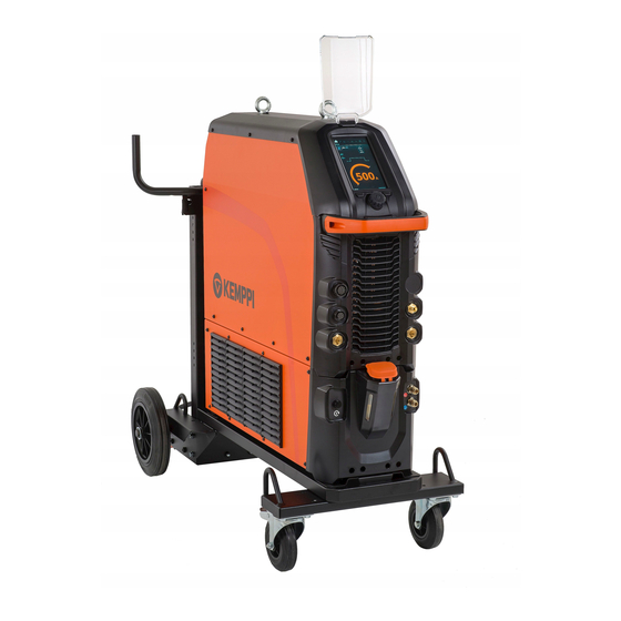
Operating manual - EN 1.1 Equipment description Kemppi MasterTig 535 AC/DC welding equipment is designed for professional industrial use, with characteristics espe- cially suitable for welding materials like aluminum and stainless steel. The multipurpose MasterTig power source is suit- able for MMA welding, TIG welding and pulsed TIG welding with both direct current (DC) and alternating current (AC). - Page 6 MasterTig 535ACDC Operating manual - EN Mains cable Cooling unit connection. EQUIPMENT IDENTIFICATION Serial number Serial number of the device is marked on the rating plate or in another distinctive location on the device. It is important to make correct reference to the serial number of the product when ordering spare parts or making repairs for example.
-
Page 7: Installation
Distribution network MasterTig 535ACDC: Provided that the public low voltage short circuit power at the point of common coupling is higher than or equal to the value stated on the list below, this equipment is compliant with IEC 61000-3-11 and IEC 61000-3-12 and can be connected to public low voltage systems. -
Page 8: Installing Mains Plug
MasterTig 535ACDC Operating manual - EN 2.1 Installing mains plug Only an authorized electrician is allowed to install the mains cable and plug. Do not connect the machine to the mains before the installation is complete. Install the 3-phase plug according to the MasterTig power source and site requirements. Refer also to "Technical data"... -
Page 9: Installing Cooling Unit (Optional)
MasterTig 535ACDC Operating manual - EN 2.2 Installing cooling unit (optional) For instructions on installing the equipment on cart, refer to "Installing equipment on cart (optional)" on page 12. The cooling unit must be installed by authorized service personnel. Do not attempt to move the power source with a hoist from its handle. The handle is meant for moving the equip- ment when installed on cart. - Page 10 MasterTig 535ACDC Operating manual - EN Route the cooling unit's connection cables so that they remain accessible through the next steps. Lift the power source with a hoist from the lifting eyes and place it on top of the cooling unit so that the fixing plates align and go into their slots.
- Page 11 Fill the cooling unit with cooling liquid. >> MasterTig Cooler MXL tank volume is 3 litres and the recommended coolant is MPG 4456 (Kemppi mixture). Avoid cooling liquid contact with skin or eyes. In case of an injury, seek for medical advice.
-
Page 12: Installing Equipment On Cart (Optional)
MasterTig 535ACDC Operating manual - EN 2.3 Installing equipment on cart (optional) There is a 4-wheel transport unit available for use with the MasterTig welding equipment. Tools needed: Install the cooling unit on the cart. Fix the cooling unit to the cart with two screws (M5x12) in the front and two screws (M5x12) in the rear. - Page 13 MasterTig 535ACDC Operating manual - EN Route the cooling unit's connection cables so that they remain accessible through the next steps. Install the power source on top of the cooling unit. Refer to "Installing cooling unit (optional)" on page 9 for install- ation details.
- Page 14 MasterTig 535ACDC Operating manual - EN Secure the equipment to the cart with the rear connection bracket. Rear screws: M8x16, top screws: M5x12. For lifting the equipment, refer to "Lifting MasterTig 535 equipment" on page 28. © Kemppi 1921940 / 2140...
-
Page 15: Connecting Tig Torch
MasterTig 535ACDC Operating manual - EN 2.4 Connecting TIG torch Gas-cooled TIG torch: Assemble the TIG torch according to the instructions delivered with the torch. Connect the TIG torch cables to the power source. Secure by turning the connectors clockwise. - Page 16 MasterTig 535ACDC Operating manual - EN Tip: For Kemppi welding torches, refer also to userdoc.kemppi.com. © Kemppi 1921940 / 2140...
-
Page 17: Connecting Earth Return Cable And Clamp
MasterTig 535ACDC Operating manual - EN 2.5 Connecting earth return cable and clamp Keep the work piece connected to earth to reduce the risk of injury to users or damage to electrical equipment. Connect the earth return cable to the negative (-) connector on the power source. -
Page 18: Connecting Mma Electrode Holder
MasterTig 535ACDC Operating manual - EN 2.6 Connecting MMA electrode holder Connect the MMA electrode holder to the positive (+) connector on the power source. Connect the earth return cable to the negative (-) connector on the power source. Ensure the earth return clamp is secured tightly to the work piece or work surface. -
Page 19: Installing Remote Control (Optional)
MasterTig 535ACDC Operating manual - EN 2.7 Installing remote control (optional) To enable remote operation, set the Remote control mode in the control panel settings. For MTP35X control panel, refer to "Settings view" on page 44. When the Remote mode is selected on the control panel, and both wireless and wired remotes are connected, the wired remote will be used. - Page 20 MasterTig 535ACDC Operating manual - EN Turn on the Wireless remote in the control panel settings. Keeping the wireless remote close to the power source, long press (3 sec.) the wireless remote pairing button on the remote. Once connected, the blue LED on the left of the connection button is lit. The green LED blinks when the battery is low.
- Page 21 MasterTig 535ACDC Operating manual - EN Take the foot pedal battery holder out. Install the batteries (3 x AAA) and put the holder back into the foot pedal. Turn on the Wireless remote in the control panel settings. Keeping the wireless remote close to the power source, long press (3 sec.) the wireless remote pairing button on the foot pedal.
-
Page 22: Installing Gas Bottle
A suitable flow rate for argon is normally 5 – 15 l/min. If the gas flow is not correctly set, this will increase the risk of defects in the weld (weld porosity). Spark ignition becomes more difficult if the gas flow is too high. Contact your local Kemppi dealer for choosing the gas and the equipment. Gas bottle valve... -
Page 23: Installing Gas Bottle On Cart
MasterTig 535ACDC Operating manual - EN 2.9 Installing gas bottle on cart Tilt the pivoting gas bottle rack down against the floor for easier gas bottle mounting. Move the gas bottle onto the rack. >> Tilt the gas bottle back and pull the cart towards the gas bottle and push the top of the gas bottle forwards. -
Page 24: Replacing Control Panel
MasterTig 535ACDC Operating manual - EN 2.10 Replacing control panel Tools needed: Detaching control panel Detach the control panel and frame from the power source: >> Remove the fixing screws at the top and bottom of the panel. >> First pull the top of the control panel slightly and then the rest of the panel. - Page 25 MasterTig 535ACDC Operating manual - EN Disconnect the control panel's cable. Remove the control panel from the frame: >> Release the clips at the top by pressing the panel from the outside. >> Release one clip at the bottom, rotate the panel slightly and release the second clip.
- Page 26 MasterTig 535ACDC Operating manual - EN Installing control panel Install the control panel to the frame. Ensure that the panel is firmly attached to the frame. Connect the new control panel’s cable. Mount the control panel in place: >> Insert the bottom of the panel in the slot first.
- Page 27 MasterTig 535ACDC Operating manual - EN © Kemppi 1921940 / 2140...
-
Page 28: Lifting Mastertig 535 Equipment
MasterTig 535ACDC Operating manual - EN 2.11 Lifting MasterTig 535 equipment If you need to lift the MasterTig 535 welding equipment, pay special attention to the safety measures. Also follow the local regulations. Connect the 2-legged chain or strap from the hoist hook to the two lifting eyes on the power source. - Page 29 MasterTig 535ACDC Operating manual - EN Lifting equipment on cart Ensure that the welding equipment is properly secured to the cart. Connect the 4-legged chain or straps from the hoist hook to the four lifting points on the cart on both sides of the welding equipment.
-
Page 30: Operation
MasterTig 535ACDC Operating manual - EN 3. OPERATION Before using the equipment, ensure that all the necessary installation actions have been completed according to your equipment setup. Welding is forbidden in places where there is an immediate fire or explosion hazard! Welding fumes may cause injury, take care of sufficient ventilation during welding! Check that there is enough space for cooling air circulation in the machine vicinity. -
Page 31: Operating Power Source
MasterTig 535ACDC Operating manual - EN 3.1 Operating power source Turn the power source ON. The power switch is located in the rear. Wait approximately 15 seconds for the system to start up. For control panel operation, refer to "Operating control panel MTP35X" on the next page. -
Page 32: Operating Control Panel Mtp35X
MasterTig 535ACDC Operating manual - EN 3.2 Operating control panel MTP35X Control panel MTP35X has a 7” TFT LCD display. In addition to setup and adjustment features, the MTP35X control panel includes memory channels, Weld Assist, option for more customized welding processes, assisting graphics and functions such as double pulse TIG, search arc and tail arc. -
Page 33: Home View
MasterTig 535ACDC Operating manual - EN • "Memory channels view" on page 38 • "Start & stop sequence view" on page 39 • "Pulse view" on page 41 • "Current mode view" on page 43 • "Settings view" on page 44 • "Info view" on page 47 To navigate between different control panel views: Press the menu button (2). -
Page 34: Weld Assist View
MasterTig 535ACDC Operating manual - EN Warning and notification symbols: a. Cooling unit • Green: Cooling unit is connected and running • Red: Cooling unit is connected, but there is a problem (e.g. coolant circulation is restricted) b. General notification •... - Page 35 MasterTig 535ACDC Operating manual - EN Using Weld Assist with TIG welding Go to the Weld Assist view and select 'Start' with the control knob button (1). Select: >> The material you are about to weld: Fe (mild steel) / Ss (stainless steel) / Al (aluminum).
- Page 36 MasterTig 535ACDC Operating manual - EN Weld Assist automatically sets the following parameters for you: • Current mode: AC / DC- • Current: Depends on the machine used • Pulse (if used): Frequency • AC and Start & stop parameters: Set to default.
- Page 37 MasterTig 535ACDC Operating manual - EN Using Weld Assist with MMA welding Go to the Weld Assist view and select 'Start' with the control knob button. Select: >> The electrode type: Fe-Basic / Fe-Rutile / High Eff. / Ss (stainless steel)/Inox.
-
Page 38: Memory Channels View
MasterTig 535ACDC Operating manual - EN Weld Assist automatically sets the following parameters for you: • Current: Depends on the machine used • Hot start • Arc force • DC+ indicates polarity (in this case the electrode holder is connected to the positive (+) DIX connector). -
Page 39: Start & Stop Sequence View
MasterTig 535ACDC Operating manual - EN To browse through channels and select channels: Go to the Memory channels view. Turn the control knob (1) to switch between channels. The highlighted channel is automatically selected. To save or delete channels: Turn the control knob (1) to highlight a channel. - Page 40 MasterTig 535ACDC Operating manual - EN To adjust parameters: Go to the Start & stop sequence view. Turn the control knob (1) to browse through the parameters. Select a parameter for adjusting by pressing the control knob button (1). Adjust the parameter by turning the control knob (1).
-
Page 41: Pulse View
MasterTig 535ACDC Operating manual - EN Parameter Value Note Post gas 0.0 s ... 30.0 s / Auto, step 0.1 s (Default = Auto) Adjustable parameters in MicroTack welding: Parameter Value Note Pre gas 0.0 s ... 10.0 s, Auto, 0.1 s step (Default =... - Page 42 MasterTig 535ACDC Operating manual - EN To adjust parameters: Go to the Pulse view. Turn the control knob (1) to browse through the parameters. Select a parameter for adjustment by pressing the control knob button (1). Adjust the parameter by turning the control knob (1).
-
Page 43: Current Mode View
MasterTig 535ACDC Operating manual - EN 3.2.6 Current mode view To adjust parameters: Go to the Current mode view. Turn the control knob (1) to browse through the parameters. Select a parameter to be adjusted by pressing the control knob (1). -
Page 44: Settings View
MasterTig 535ACDC Operating manual - EN "Welding processes and features" on page 62 3.2.7 Settings view To adjust settings: Go to the Settings view. Turn the control knob (1) to browse through the settings groups and parameters. Select a parameter to be adjusted or changed by pressing the control knob button (1). - Page 45 MasterTig 535ACDC Operating manual - EN Common welding settings: Parameter Value Note Current limit min TIG: 2 A / MMA: 8 A, step 1 A * Current limit max TIG: power source's nominal value / MMA: power source's max. MMA current,...
- Page 46 (Default = 5 min) Display off time OFF / 1 min ... 120 min (Default = 5 min) Screen saver image Default = Kemppi logo An alternative screen saver image can be used. For more information, refer to "Screen saver" on page 48.
-
Page 47: Info View
MasterTig 535ACDC Operating manual - EN * Current range adjustable by welder in TIG welding: • 2 A ... 505 A (400 V), step 1 A >> Default = Nominal value of the power source. • 2 A ... 455 A (220 V), step 1 A >>... -
Page 48: Screen Saver
Remove the USB memory stick and install the control panel back in place. Refer to "Replacing control panel" on page 24 for more information. To delete a custom screen saver image from the control panel memory, or to use the Kemppi logo instead, go to "Set- tings view" on page 44. -
Page 49: Operating Cooling Unit
MasterTig 535ACDC Operating manual - EN 3.3 Operating cooling unit Ensure there is cooling liquid in the tank and that the welding torch is connected. Press and briefly hold the cooling liquid circulation button on the cooling unit’s front. This activates a pump motor which pumps the cooling liquid into the hoses and to the welding torch. -
Page 50: Remote Control
MasterTig 535ACDC Operating manual - EN 3.4 Remote control For installing remote control, refer to "Installing remote control (optional)" on page 19. Hand remote control: To adjust the welding current, turn the knob on the remote control. Tip: The remote control comes equipped with a handy clip for hanging the remote onto your belt. - Page 51 MasterTig 535ACDC Operating manual - EN Tip: To shift the foot pedal position on the floor, use the foot pedal handle. © Kemppi 1921940 / 2140...
-
Page 52: Maintenance
Do not use pressure washing devices. Service workshops Kemppi Service Workshops complete the welding system maintenance according to the Kemppi service agreement. The main aspects in the service workshop maintenance procedure are: • Cleanup of the machine •... -
Page 53: Troubleshooting
The circulation must be at least 0.5 l/min. • Make sure you are using original Kemppi consumable and spare parts. Incorrect spare part materials may also cause overheating. •... -
Page 54: Error Codes
Power source Power source calibration has been lost. Restart the power source. If problem persists, contact not calibrated Kemppi service. Note: The equipment operation is lim- ited when this error occurs. Too low mains Voltage in mains network is too low. - Page 55 MasterTig 535ACDC Operating manual - EN Error Error descrip- Possible reason Proposed action code tion Internal Initialization failed. Restart welding system. If problem persists, contact memory failure Kemppi service. Internal Memory communication failed. Restart welding system. If problem persists, contact memory failure Kemppi service.
-
Page 56: Disposal
The owner of the equip- ment is obliged to deliver a decommissioned unit to a regional collection center, as per the instructions of local author- ities or a Kemppi representative. By applying these European Directives you improve the environment and human health. -
Page 57: Technical Data
MasterTig 535ACDC Operating manual - EN 5. TECHNICAL DATA Technical data: "Power source MasterTig 535ACDC" on the next page "Cooling unit MasterTig Cooler MXL" on page 60 Additional information: For ordering information, refer to "Ordering info" on page 68. © Kemppi 1921940 / 2140... -
Page 58: Power Source Mastertig 535Acdc
MasterTig 535ACDC Operating manual - EN 5.1 Power source MasterTig 535ACDC MASTERTIG 535ACDCG M Feature Value Mains connection voltage 3~ 50/60 Hz 380...460 V ±10 % 220...230 V ±10 % Mains connection cable 6 mm Maximum supply current 31...27 A @ 380...460 V 1max 44...42 V @ 220...230 V... - Page 59 MasterTig 535ACDC Operating manual - EN MASTERTIG 535ACDCG M Feature Value Weight without accessories 57 kg Arc-on signal for relay 24 V / 50 mA Voltage supply for cooling unit 220 ... 460 V Recommended generator power (min) 35 kVA...
-
Page 60: Cooling Unit Mastertig Cooler Mxl
1.0 A 1max Rated cooling power at 1 l/min 1.7 kW Cooling power at 1 l/min 1.7 kW Recommended coolant MPG 4456 (Kemppi mixture) Coolant pressure (max) 0.4 MPa Tank volume 3.0 l Operating temperature range * -20 ... +40 °C Storage temperature range -20 ... -
Page 61: Tig Guide Tables
MasterTig 535ACDC Operating manual - EN 5.3 TIG guide tables The tables in this chapter are given only as a general guidance. The information provided is based solely on the use of WC20 (grey) electrode and Argon gas. TIG welding (AC) -
Page 62: Welding Processes And Features
MasterTig 535ACDC Operating manual - EN 5.4 Welding processes and features MasterTig 535 2T downslope cut This is a function that allows the user to end the current downslope ramp with a quick press of the torch switch. AC Balance Function to adjust the positive and negative current cycles in AC TIG welding. - Page 63 MasterTig 535ACDC Operating manual - EN Balance maximum Sets the maximum value for AC balance setting. Balance minimum Sets the minimum value for AC balance setting. Base current The lower current level of the pulse cycle. In TIG welding, its main tasks are to cool down the weld pool and to maintain the arc.
- Page 64 MasterTig 535ACDC Operating manual - EN Ignition current Adjusts the current level of the negative ignition sequence (TIG). Ignition mode The way in which the welding arc is ignited. In TIG welding, two ignition modes are available: High Frequency (HF) ignition and Lift TIG ignition. The HF ignition uses a voltage pulse to initiate the arc, and the Lift TIG igni- tion needs a physical contact between the electrode and the work piece.
- Page 65 MasterTig 535ACDC Operating manual - EN MMA antifreeze A function which automatically decreases the welding current significantly when electrode is touching the workpiece. Can be used for avoiding MMA electrode getting too hot when it’s in contact with the workpiece.
- Page 66 MasterTig 535ACDC Operating manual - EN Pulse TIG TIG welding process, where the welding current changes between two current levels: base current and pulse current. Parameters can be set either manually or automatically. Used for optimizing the arc characteristics for desired welding applications.
- Page 67 MasterTig 535ACDC Operating manual - EN welding. Trigger logic 4T Trigger operation mode of a welding torch. When you press the trigger down in 4T mode, shielding gas starts to flow but the arc won’t ignite until you release the trigger. To stop welding you press the trigger down again and then release it to extinguish the arc.
- Page 68 Operating manual - EN 5.5 Ordering info For ordering information and optional accessories, refer to Kemppi.com. For connection options of all gun and torch models and corresponding remote controls, refer to Kemppi Userdoc at https://kemp.cc/connectivity. © Kemppi 1921940 / 2140...
Need help?
Do you have a question about the MasterTig 535ACDC and is the answer not in the manual?
Questions and answers