
Subscribe to Our Youtube Channel
Related Manuals for Kemppi PROMIG 511


Summary of Contents for Kemppi PROMIG 511
- Page 1 1923410E Operation instructions • english 0537 Gebrauchsanweisung • deutsch Gebruiksaanwijzing • nederlands Manuel d’utilisation • français PROMIG 501, 511 PROMIG 501L...
-
Page 2: Table Of Contents
ERROR CODES OF PANELS ..................30 SERVICE, OPERATION DISTURBANCES ..............31 DISPOSAL OF THE MACHINE ..................31 PROMIG 501L ....................... 32 ORDERING NUMBERS ....................33 TECHNICAL DATA ......................35 TERMS OF GUARANTEE ..................... 36 2 – PROMIG 501, PROMIG 511/0537 © KEMPPI OY... -
Page 3: Preface
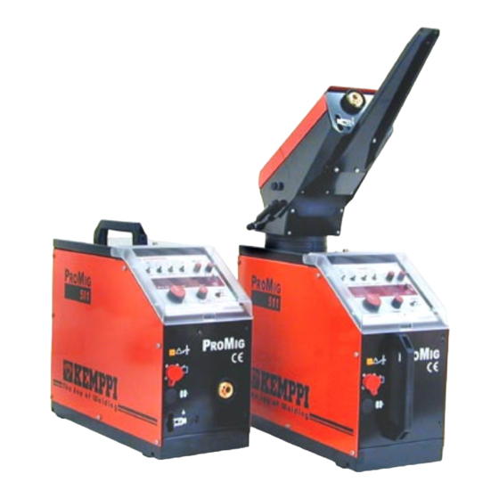
Promig 501 and Promig 511 are wire feeders designed for demanding professional use. Promig 501 and Promig 511 are based on same technical solutions. Promig 511 has as additional characteristic an integrated swing arm for gun which makes working easier. -
Page 4: Operation Control And Connectors
Connection for control cable, MIG / TIG Control cable, PRO power source Inlet for cooling liquid hoses Welding current cable, PRO power source Wire inch Selection of air/liquid cooling Hook catch for keeping door open Accessory drawer 4 – PROMIG 501, PROMIG 511/0537 © KEMPPI OY... - Page 5 R3/8 - Snap connector Shielding gas hose Snap connector - 0 Welding current cable Extension cable for remote control Earth cable MMA welding cable PRO 3200 MIG gun liquid-cooled 4200 5200 © KEMPPI OY PROMIG 501, PROMIG 511/0537 – 5...
-
Page 6: Parts Of Wire Feed Mechanism
�������������� ������� ������ ����� ������� �� ������ ���� �� ������������� ������� ������������� ������� ������������� ������� ��������� �� ������ ����� ���� �� ������������� ������� ��������� ������� �� ������ ����� �� ��������������� ��� 6 – PROMIG 501, PROMIG 511/0537 © KEMPPI OY... - Page 7 �������������� ������� ������ ����� ������� �� ������ ���� �� ������������� ������� ������������� ������� ������������� ������� ��������� �� ������ ����� ���� �� ������������� ������� ��������� ������� �� ������ ����� �� ��������������� ��� © KEMPPI OY PROMIG 501, PROMIG 511/0537 – 7...
-
Page 8: Quick Guide For Operation Of Mc Panel
3. Adjust required MMA current. Values are shown in displays 4. Set welding dynamics on position zero or on required position 5. Weld and adjust MMA current when needed 8 – PROMIG 501, PROMIG 511/0537 © KEMPPI OY... -
Page 9: Quick Guide For Operation Of Ml Panel
3. Adjust required MMA current. Values are shown in displays 4. Set welding dynamics on position zero or on required position 5. Weld and adjust MMA current when needed © KEMPPI OY PROMIG 501, PROMIG 511/0537 – 9... -
Page 10: Operation Safety
Do not press MIG-gun switch, if the gun is not directed towards a work piece. Welding fumes Take care that there is sufficient ventilation during welding. Take special safety precautions when welding metals which contain lead, cadmium, zinc, mercury or beryllium. 10 – PROMIG 501, PROMIG 511/0537 © KEMPPI OY... -
Page 11: Installation
Too small gap between gear wheel and feed rolls will overload motor. Too big gap for its part might cause too rapid wearing for teeth of feed rolls and gear wheel. © KEMPPI OY PROMIG 501, PROMIG 511/0537 – 11... -
Page 12: Accessories Corresponding To Wire Diameter
(also see error codes on page 30): 1. Thermal release of the KEMPPI PMT or WS gun is operating. Then the equipment stops the welding, yellow signal lamp H11 starts to blink and at the same time on (wire feed) display of panel appears the text Err 8. -
Page 13: Mounting And Locking Of Wire Reel
– Press the gun switch and feed a bit wire until wire goes through feed rolls to gun. See that wire is in grooves of both feed roll pairs! – Press still the gun switch until wire has come through contact tip. © KEMPPI OY PROMIG 501, PROMIG 511/0537 – 13... -
Page 14: Adjustment Of Pressure
. Thinner cross-sectional areas might cause overheating of connectors and insulations. Make sure that the welding gun in your use is designed for max. welding current needed! Never use a damaged welding gun! 14 – PROMIG 501, PROMIG 511/0537 © KEMPPI OY... -
Page 15: Shielding Gas
The flow rate is set according to the welding power used in the job. A suitable flow rate is normally 8 - 10 l/min. If the gas flow is not suitable, the welded joint will be sporous. Contact your local Kemppi-dealer for choosing gas and equipment. 2.10.1. Installing gas bottle Always fasten gas bottle properly in vertical position in a special holder on the wall or on a carriage. -
Page 16: Main Switch I/O
Local controls: wire feed speed/MMA current (R21), welding voltage (R22) Controls for MIG and MMA welding dynamics (R23) Digital displays: wire feed speed (P21), current (P22), voltage (P23) Retrieval of last used welding values (S23) 16 – PROMIG 501, PROMIG 511/0537 © KEMPPI OY... - Page 17 Gun control: Wire feed speed is adjusted with control module RMT 10 which is connected to KEMPPI PMT or WS welding gun and welding voltage is adjusted with potentio- meter. Note! If the remote control unit or the gun control unit is not connected to the PROMIG and you have selected remote control or gun control, then controls operate with local controlpotentiometers like in local control position.
- Page 18 Display shows set value for welding voltage and true value during welding. MMA welding: Display shows in setting state open circuit voltage of power source and true value during welding for MMA welding voltage. 18 – PROMIG 501, PROMIG 511/0537 © KEMPPI OY...
-
Page 19: Weld Data / Gas Test
Search of welding data for storage. Welding data are stored for wished channel by using the SAVE switch. Those values for wire feed speed, voltage and welding dynamics are stored, which were set before using the SAVE switch. © KEMPPI OY PROMIG 501, PROMIG 511/0537 – 19... -
Page 20: Ml Control Panel
Local controls: wire feed speed/welding power/MMA current (R31), welding voltage (R32) Controls for MIG and MMA welding dynamics (R33) Digital displays: wire feed speed (P31), current (P32), voltage (P33) Retrieval of last used welding values (S33) 20 – PROMIG 501, PROMIG 511/0537 © KEMPPI OY... - Page 21 Gun control: Wire feed speed/welding power is adjusted with control module RMT 10 which is connected to KEMPPI PMT or WS welding gun and welding voltage/arc length is adjusted with potentiometer U on panel. Note! If the remote control unit or the gun control unit is not connected to the PROMIG and you have selected remote control or gun control, then controls operate with local control potentiometers like in local control positions.
- Page 22 -9...-1 Wider pulsed MIG arc. Object: e.g. welding of square butt preparation Recommendable basic setting 1...9 More narrow and better directed arc. Object: e.g. fillet weld seams of thin basic materials 22 – PROMIG 501, PROMIG 511/0537 © KEMPPI OY...
- Page 23 Display shows in setting state value -9...0...9 for arc length and during welding true value of welding voltage. MMA welding: Display shows in setting state open circuit voltage of power source and true value for MMA welding voltage during welding. © KEMPPI OY PROMIG 501, PROMIG 511/0537 – 23...
-
Page 24: Weld Data
SYNERGIC operation is not in use. 1-MIG SYNERGIC MIG welding with parameters which are optimized according to filler wire parameters. Nine SYNERGIC MIG programs for different filler wires are stored: 24 – PROMIG 501, PROMIG 511/0537 © KEMPPI OY... - Page 25 2. Weld at power level wanted by you 3. Adjust with potentiometer for cable compensation a suitable arc length 4. Check adjustment range for arc length by adjusting arc length -9...0...9 5. When needed repeat points 2...4 © KEMPPI OY PROMIG 501, PROMIG 511/0537 – 25...
- Page 26 Set values connected with these min. and max. powers are shown in set value displays. Compensating cable length See the paragraph: ”SYNERGIC MIG welding”. 26 – PROMIG 501, PROMIG 511/0537 © KEMPPI OY...
-
Page 27: Operations Of Remote Control Units In Promig 501 And 511 Wire Feed Units
Setting for power (wire feed speed): according to wire min..max. SYNERGIC Setting for power (wire feed speed): PULSED MIG according to wire min..max. Setting for power: NOTE ! RMT10 10 A...max.power of power source NO OPERATION © KEMPPI OY PROMIG 501, PROMIG 511/0537 – 27... -
Page 28: Promig 501, 511 A001 Jumper Block Functions
0-5 V –>0-18,25 m/min, U2: 0-5 V –> 0-50 V Disable PMT or WS MIG guns PMT, WS and RMT10 functions enabled PMT, WS and RMT10 functions disabler (Err11), only normal guns pos- sible to use 28 – PROMIG 501, PROMIG 511/0537 © KEMPPI OY... - Page 29 Extra label needed to change Fe text to AlSi text Amperage display is on with MX-panel Selection of max wire feed speed Max. speed 18 m/min, on delivery Max. speed 25 m/min © KEMPPI OY PROMIG 501, PROMIG 511/0537 – 29...
-
Page 30: Error Codes Of Panels
Blinking of error codes Err 2-4 ends automatically within 5 s, if the trigger is not pressed down. Eliminate the reason of error before next start. Blinking of error codes Err 5-12 ends by next start, if the reason of error code has been elimina- ted. 30 – PROMIG 501, PROMIG 511/0537 © KEMPPI OY... -
Page 31: Service, Operation Disturbances
Clean dust and dirt from the equipment. When using compressed air, always protect your eyes with proper eye protection. In case of problems contact your KEMPPI dealer. 8. DISPOSAL OF THE MACHINE Do not dispose of electrical equipment together with normal waste! -
Page 32: Promig 501L
PROMIG 501L 32 – PROMIG 501, PROMIG 511/0537 © KEMPPI OY... -
Page 33: Ordering Numbers
MMT 32 6253213MMT MMT 32 4,5 m 6253214MMT MMT 35 6253513MMT MMT 35 4,5 m 6253514MMT MMT 42 6254213MMT MMT 42 4,5 m 6254214MMT KMP 300 6257306 KMP 300 10 m 6257310 © KEMPPI OY PROMIG 501, PROMIG 511/0537 – 33... - Page 34 6253048S12 WS 42W (Al 1.2-1.6) 6254206A12 WS 42W (SS 1.0) 6254206S10 WS 42W (SS 1.2) 6254206S12 WS 42W (Al 1.2-1.6) 6254208A12 WS 42W (SS 1.0) 6254208S10 WS 42W (SS 1.2) 6254208S12 34 – PROMIG 501, PROMIG 511/0537 © KEMPPI OY...
-
Page 35: Technical Data
Measuring recording to memory, retrieval of welding parameters (WPS) MIG/MMA dynamics control Potentiometer Potentiometer Selecto memory channels 5 pc –– Synergic MIG –– 9 programs Synergic PULSED MIG –– 9 programs © KEMPPI OY PROMIG 501, PROMIG 511/0537 – 35... -
Page 36: Terms Of Guarantee
Guarantee repairs must be carried out only by an Authorised Kemppi Service Agent. Packing, freight and insurance costs to be paid by orderer. The guarantee is effected on the date of purchase. Verbal promises which do not comply with the terms of guarantee are not binding on guarantor. - Page 37 Tel (06033) 88 020 KEMPPI NORGE A/S Telefax (06033) 72 528 Postboks 2151, Postterminalen e-mail:sales.de@kemppi.com N – 3103 TØNSBERG KEMPPI SP. z o.o. NORGE Ul. Piłsudskiego 2 Tel 33 34 60 00 05-091 ZA¸BKI Telefax 33 34 60 10 Poland e-mail: sales.no@kemppi.com...
Need help?
Do you have a question about the PROMIG 511 and is the answer not in the manual?
Questions and answers