Sign In
Upload
Manuals
Brands
VersaLogic Manuals
Single board computers
BayCat VL-EPM-31EBP
VersaLogic BayCat VL-EPM-31EBP Manuals
Manuals and User Guides for VersaLogic BayCat VL-EPM-31EBP. We have
1
VersaLogic BayCat VL-EPM-31EBP manual available for free PDF download: Hardware Reference Manual
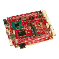
VersaLogic BayCat VL-EPM-31EBP Hardware Reference Manual (77 pages)
Brand:
VersaLogic
| Category:
Single board computers
| Size: 3.75 MB
Table of Contents
Table of Contents
7
Introduction
12
Description
12
Figure 2. VL-EPM-31 Baycat Single Board Computer (Top Side)
13
Technical Specifications
14
Thermal Considerations
14
Figure 3. VL-EPM-31 Baycat Single Board Computer (Bottom Side)
14
EPM-31 Block Diagram
15
Figure 4. EPM-31 Block Diagram
15
Dimensions and Mounting
16
Figure 5. EPM-31 Dimensions and Mounting Holes
16
Hardware Assembly
17
Related Documents
17
Configuration and Setup
18
Initial Configuration
18
Basic Setup
18
Jumper Blocks
20
Jumpers Blocks in the As-Shipped Configuration
20
Jumper Summary
20
Figure 6. Jumper Block Locations
20
Table 1: Jumper Summary
20
Configuration Switches
21
Figure 7. Location of SW1 Configuration Switch Block
21
Table 2: Switch Setting Summary
21
Clearing Non-Volatile RAM and RTC Registers
22
Resetting the BIOS to Factory Defaults
22
BIOS Setup Utility
22
Operating System Installation
23
Board Features
24
Cpu
24
System RAM
24
I/O Interfaces
24
Power Delivery
25
Main Power Connector
25
Figure 8. Location and Pin Orientation of the Main Power Connector
25
Cabling
26
Power Delivery Considerations
26
Table 3: J20 Main Power Connector Pinout
26
Power Button
27
Supported Power States
27
Table 4: Supported Power States
27
Battery Power Options
28
Cabling
28
Figure 9. Location and Pin Orientation of the External Battery Connector
28
VL-CBR-0203 External Battery Module
29
Real Time Clock (RTC)
29
Push-Button Reset
29
Figure 10. VL-CBR-0203 Latching Battery Module
29
Leds/Indicators
30
Programmable LED
30
Figure 11. Locations of the Leds/Indicators
30
Power Leds
31
External Speaker
31
Figure 12. Location of the D11 Dual-Color LED
31
Mass Storage Interfaces
32
Sata
32
Figure 13. Location of the SATA Port
32
Microsd Socket
33
Figure 14. Location of the Microsd Socket
33
Multi-Purpose I/O
34
USB Interfaces
34
Figure 15. Location of the USB 3.0 Port (Bottom Side of the Board)
34
Cabling
35
Pcie Mini Card / Msata
35
Table 5: USB 3.0 J16 Connector Pinout
35
Table 6: Pcie Mini Card / Msata Pinout
35
Figure 16. Location of the Sata/Msata Activity LED
37
Msata Activity LED
37
Pcie Mini Card Leds
38
Table 7: Pcie Mini Card LED States
38
User I/O Connector
39
Cabling
40
Table 8: J4 I/O Connector Pinout and Pin Orientation
40
Digital I/O (DIO)
41
DIO Guidelines
42
Voltage
42
Table 9: J21 I/O Connector Pinout
42
Power States
43
Cables
43
Serial Ports
44
Serial Port Connectors
44
Serial Port Connector Pinouts
45
Cabling
45
RS-485 Mode Line Driver Control
45
Table 10: J13 COM1/COM2 Connector Pinout
45
COM1/COM2 Hardware Configuration
46
Table 11: COM3/COM4 Termination Jumpers
46
Video Interfaces
47
VGA Interface
47
Cabling
48
Table 12: J5 VGA Video Output Pinout
48
Mini Displayport Connector
49
Console Redirection
50
Table 13: J3 Mini Displayport Connector Pinout
50
Network Interfaces
51
Ethernet Connector
51
Cabling
52
Table 14: Ethernet Connector Pinout
52
On-Board Ethernet Status Leds
53
Table 15: Ethernet Status Leds
53
Expansion Interfaces
54
SPX™ Expansion Bus
54
Cabling
55
Versalogic SPX Expansion Modules
55
Table 16: SPX Connector Pinout
55
PC/104-Plus Expansion Bus
56
ISA Bus (on PC/104-Plus and PC/104 Expansion Modules)
56
Table 17: PCI/104-Plus Connector (PCI) Maximum Current
56
ISA I/O Support
57
ISA Memory Support
57
ISA IRQ Support
58
Each of the Irqs Must be Enabled in the BIOS Setup Utility before They Can be Used. (All Are Disabled by Default.)
58
PCI Bus (on PC/104-Plus and PCI-104 Expansion Modules)
58
System Resources and Maps
59
CBR-4005B Paddleboard
60
CBR-4005B Connectors and Indicators
60
User I/O Connector
61
Cabling
62
On-Board Battery
62
Auxiliary I/O Connector
63
Dimensions and Mounting Holes
64
CBR-2004B Paddleboard
65
CBR-2004B Connectors
65
Main I/O Connector
66
Cabling
66
Dimensions and Mounting Holes
67
Thermal Considerations
68
Selecting the Correct Thermal Solution for Your Application
68
Heat Plate
68
System-Level Considerations
69
CPU Thermal Trip Points
70
Thermal Specifications, Restrictions, and Conditions
71
Overall Restrictions and Conditions
71
Heat Plate Only Restrictions and Conditions
71
Heat Sink Only Considerations
71
Heat Sink with Fan Considerations
71
EPM-31 Thermal Characterization
72
Test Results
73
Installing the Versalogic Thermal Solutions
76
Installing the Passive Heat Sink
76
Installing the Heat Sink Fan
77
Advertisement
Advertisement
Related Products
VersaLogic VL-EPM-24
VersaLogic VL-EPMs-21
VersaLogic BayCat VL-EPM-31ECP
VersaLogic Tetra VL-EPC-2700
VersaLogic VL-EPU-3310
VersaLogic VL-EPU-4011
VersaLogic Komodo VL-EPICs-36
VersaLogic Viper VL-EBX-38ECP
VersaLogic Viper VL-EBX-38EBP
VersaLogic Viper VL-EBX-38EAP
VersaLogic Categories
Motherboard
Computer Hardware
Single board computers
Control Unit
Power Supply
More VersaLogic Manuals
Login
Sign In
OR
Sign in with Facebook
Sign in with Google
Upload manual
Upload from disk
Upload from URL