Table of Contents
Advertisement
Quick Links
Advertisement
Table of Contents

Related Manuals for HIKVISION DS-M5504HNI Series


Summary of Contents for HIKVISION DS-M5504HNI Series
- Page 1 Mobile Network Video Recorder User Manual UD.6L0204D1120A01...
- Page 2 COPYRIGHT ©2015 Hangzhou Hikvision Digital Technology Co., Ltd. ALL RIGHTS RESERVED. Any and all information, including, among others, wordings, pictures, graphs are the properties of Hangzhou Hikvision Digital Technology Co., Ltd. or its subsidiaries (hereinafter referred to be “Hikvision”). This user manual (hereinafter referred to be “the Manual”) cannot be reproduced, changed, translated, or distributed, partially or wholly, by any means,...
- Page 3 Mobile Network Video Recorder User Manual Regulatory Information FCC Information Please take attention that changes or modification not expressly approved by the party responsible for compliance could void the user’s authority to operate the equipment. Note: This product has been tested and found to comply with the limits for a Class B digital device, pursuant to Part 15 of the FCC Rules.
- Page 4 Mobile Network Video Recorder User Manual Le pré sent appareil est conforme aux CNR d'Industrie Canada applicables aux appareils radioexempts de licence. L'exploitation est autorisé e aux deux conditions suivantes : (1) l'appareil ne doit pas produire de brouillage, et (2) l'utilisateur de l'appareil doit accepter tout brouillage radioé...
- Page 5 Mobile Network Video Recorder User Manual Safety Instruction These instructions are intended to ensure that user can use the product correctly to avoid danger or property loss. The precaution measure is divided into “Warnings” and “Cautions” Warnings: Serious injury or death may occur if any of the warnings are neglected. Cautions: Injury or equipment damage may occur if any of the cautions are neglected.
- Page 6 20cm if both of them are installed. The system is made of sophisticated electronics and do not disassemble the device by yourself. Contact the qualified technician from Hikvision or authorized dealer if there is any question or request.
-
Page 7: Product Key Features
Mobile Network Video Recorder User Manual Product Key Features General User-friendly GUI providing easy and flexible operations Each channel supporting up to 1080P resolution with high-efficient and flexible H.264 encoding technology Up to 4 IP cameras can be added ... - Page 8 Mobile Network Video Recorder User Manual Backup Export video data by USB device Export video data by pluggable HDD Management and maintenance of backup devices Alarm and Exception Management of alarm input/output Management of video loss alarm, motion detection alarm, video tampering alarm ...
-
Page 9: Table Of Contents
Mobile Network Video Recorder User Manual TABLE OF CONTENTS Product Key Features .............................. 6 Chapter 1 Introduction ............................10 Front Panel ..............................10 Rear Panel ..............................11 IR Remote Control Operations ........................11 USB Mouse Operations ..........................13 Starting Up and Shutting Down the Device ....................14 1.5.1 Vehicle Ignition Startup and Time-delay Shutdown ................. - Page 10 Mobile Network Video Recorder User Manual Wi-Fi Settings ............................48 Chapter 6 Platform Settings ..........................51 Accessing by iVMS Platform ........................51 Accessing by Push Mode Platform ......................51 Chapter 7 Mobile Specified Functions......................53 Configuring Startup and Shutdown ......................53 Configuring Satellite Positioning .......................
-
Page 11: Chapter 1 Introduction
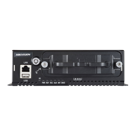
Mobile Network Video Recorder User Manual Chapter 1 Introduction 1.1 Front Panel The front panel of DS-M5504HNI series is displayed below: Figure 1. 1 Front Panel Table 1. 1 Description of Front Panel Name Description 1 RJ45 10M / 100M self-adaptive PoE interfaces. -
Page 12: Rear Panel
Mobile Network Video Recorder User Manual 1.2 Rear Panel The rear panel of DS-M5504HNI series is displayed below: Figure 1. 2 Rear Panel Table 1. 2 Description of Rear Panel Name Description PoE1 to POE4 PoE interfaces connectable to IP cameras, providing the power supply... - Page 13 Mobile Network Video Recorder User Manual Figure 1. 3 Remote Control Table 1. 3 Description of the IR Remote Control Buttons Name Description Reserved Power Input device number. 1. Input number, symbol, and character. Number keys 2. Switch to the corresponding channel in Live View mode. 1.
-
Page 14: Usb Mouse Operations
Mobile Network Video Recorder User Manual Up, Down, Left, Right 1. The DIRECTION buttons are used to navigate between different fields and items in menus. DIRECTION Buttons 2. In the playback interface, they are used for fast forward, slow forward, rewind. -
Page 15: Starting Up And Shutting Down The Device
Mobile Network Video Recorder User Manual Name Action Description Menu: Select and enter. Single-click Checkbox: Check / Uncheck the checkbox. Left-click Double-click Live View: Switch single-screen and multi-screen. Click-and-drag Tamper-proof, privacy mask, motion detection: Select target area. Live View: Show right-click menu. Right-click Single-click Menu: Go back to upper-level menu. - Page 16 Mobile Network Video Recorder User Manual Positive pole ignition switch Figure 1. 4 Connection of Positive Pole Ignition Switch Ignition switch is connected to the positive pole of DC+12/24V of vehicle batteries. Please make sure that the connection is correct, and then perform the following steps: Steps: Connect the “DC IN +”...
-
Page 17: Timing On/Off
1.6.1 Alarm Input Connection DS-M5504HNI series mobile NVR adopts the high/low-level electrical signals triggering (high level: 6 to 36 VDC; low level: 0 to 5 VDC) to realize alarm input. And in order to avoid error report caused by voltage fluctuation, no alarm will be triggered by voltage ranging of 5 to 6VDC. -
Page 18: Alarm Output Connection
Mobile Network Video Recorder User Manual 1.6.2 Alarm Output Connection The alarm output interfaces B1 and C1 of the mobile NVR is closed normally if no alarm occurs. When an alarm output is triggered, the corresponding A1 and B1 interfaces will be connected. Thus, the active alarm device is required for the system. - Page 19 Mobile Network Video Recorder User Manual Insert the key and turn in counterclockwise to open the hard disk lock, unfasten the screws counterclockwise and pull out the hard disk box. The hard disk lock is locked when the keyhole stands upwards and is open when the keyhole stands leftward.
- Page 20 Mobile Network Video Recorder User Manual After the HDD is fully placed into the bracket, reverse the hard disk box and flat the HDD. There are two disk sockets in the bracket and tightly insert the first HDD into the one at the bottom.
- Page 21 Mobile Network Video Recorder User Manual After the HDD is fully placed into the bracket, tightly insert the second HDD into the socket. Fix and tighten the two screws marked in the figure. Tighten the two set screws on the left and right sides of the hard disk box, shown in the figure, to fix the inserted HDD.
-
Page 22: Sim Card Installation
Mobile Network Video Recorder User Manual Tighten the two set screws of the hard disk box, as shown in the figure. Insert the hard disk box back to the mobile NVR, and then tighten the screws clockwise. 1.8 SIM Card Installation Pluggable wireless network module is designed for the mobile NVR and you should install the SIM card to realize the 3G function. - Page 23 Mobile Network Video Recorder User Manual Hold the small handle tightly and pull the 3G module component out of the device. Press the yellow button on the 3G module component to pop up the corresponding SIM card socket. And then remove the SIM card socket.
-
Page 24: Cable Hooks Installation
Mobile Network Video Recorder User Manual Install the 3G module component back to the mobile NVR, and tighten the set screw. 1.9 Cable Hooks Installation Steps: Prepare the IP camera dedicated cable hooks. Make sure that the two cable hooks on the left-side faces leftward;... - Page 25 Mobile Network Video Recorder User Manual Insert the network cable into the PoE interface through the cable hook, as shown in the figure. To disconnect the network cable, you can remove the clip locating on the opening of hook, shown in the figure, and then release the network cable.
-
Page 26: Chapter 2 Basic Operations
Mobile Network Video Recorder User Manual Chapter 2 Basic Operations 2.1 Setting Admin Password Purpose: For the first-time access, you need to activate the device by setting an admin password. No operation is allowed before activation. Steps: 1. Input the same password in the text field of Create New Password and Confirm New Password. Figure 2. -
Page 27: User Management
Mobile Network Video Recorder User Manual Right click on the screen, and then select the Menu item on the right-click menu to enter the main page. Operations On Main Page Option 1 (using remote control): Move the cursor via the direction buttons to select the sub-menu icon, and then press the Enter button to enter the interface of the sub-menu. -
Page 28: Ipc Settings
Mobile Network Video Recorder User Manual Figure 2. 3 User Management Click the Add button to enter the Add User interface. Figure 2. 4 Add User Input the information of the new user, including user name, password and confirm password. STRONG PASSWORD RECOMMENDED–... -
Page 29: Activating Ip Cameras
Mobile Network Video Recorder User Manual Figure 2. 5 IP Camera Settings 2.4.1 Activating IP Cameras Purpose: Before adding the cameras, make sure the IP cameras to be added are in active status. Steps: Enter IPC Settings interface. Menu > Other Settings > IPC Settings Figure 2. -
Page 30: Adding Ip Cameras
Mobile Network Video Recorder User Manual Figure 2. 7 Activate IP Camera Manually Input New Password and Confirm. STRONG PASSWORD RECOMMENDED– We highly recommend you create a strong password of your own choosing (using a minimum of 8 characters, including upper case letters, lower case letters, numbers, and special characters) in order to increase the security of your product. -
Page 31: Setting Ip Cameras
Mobile Network Video Recorder User Manual Adding IP Camera Manually Click the ManuAdd button to enter the Add IP Camera Manually page. Select the IP channel No. for the IP camera. Input the required information, including the IP address, protocol, port No., user name and password. Click the Protocol button, and you can customize the protocol according to the actual needs. -
Page 32: Deleting Ip Cameras
Mobile Network Video Recorder User Manual 2.4.4 Deleting IP Cameras Select the IP camera on the list, and click Delete button. Confirm the pop-up dialog box, and the selected IP camera is deleted from the system. Figure 2. 11 Delete IP Camera 2.5 Display Settings Purpose: You can set the system time, select the CVBS output standard, enable the password, configure the DST settings, etc. - Page 33 Mobile Network Video Recorder User Manual For mouse operations, you can click the arrow icon to adjust the date and time. Select the VGA resolution from the drop-down list. The VGA resolution is only configurable when the Mobile NVR is connected to a VGA monitor. And you can set it as 1024*768/60Hz, 1280*720/60Hz, 1280*1024/60Hz or 1920*1080/60Hz.
-
Page 34: Camera Settings
Mobile Network Video Recorder User Manual The smaller the proportion value is, the more transparent the menu is. When the Not Transparent is selected, only the menu is displayed on the interface. Operation Timeout: If no operations are done during the selected time, the live view interface will be displayed automatically. - Page 35 Mobile Network Video Recorder User Manual Select the date format and time format according to the actual needs, and then select the OSD property. Click the OSD Position button and use the F2 key and Direction keys on remote control to adjust the OSD position. Click the Set button of More Setting, and you can configure the video parameters, mask area, motion detection, etc.
-
Page 36: Preview Settings
Mobile Network Video Recorder User Manual The mask area information of one channel cannot be copied to another one. You cannot view the image of the mask area either from the live view interface or record files. The screen is divided into 22*18 blocks in PAL format and 22*15 blocks in NTSC format. - Page 37 Mobile Network Video Recorder User Manual Use the Direction keys on the remote control to select the icon on the screen, and press the Enter key to go to the previous / next display window. Select the display window, and press Enter key on the remote control to enter the edit mode. Press Direction keys on the remote control to select the camera for display.
-
Page 38: Chapter 3 Ptz Controls
Mobile Network Video Recorder User Manual Chapter 3 PTZ Controls 3.1 Configuring PTZ Settings Purpose: Follow the procedure to set the parameters for PTZ. The configuring of the PTZ parameters should be done before you control the PTZ camera. Before you start: Add a PTZ camera. -
Page 39: Setting Ptz Presets, Patrols & Patterns
Mobile Network Video Recorder User Manual Table 3. 1 Description of PTZ Control Panel Icon Description Icon Description Icon Description Direction button and Zoom+, Focus+, Zoom-, Focus-, Iris- the auto-cycle button Iris+ Moving speed Light on/off Wiper on/off 3D-Zoom Image Centralization 3.3 Setting PTZ Presets, Patrols &... -
Page 40: Calling Presets
Mobile Network Video Recorder User Manual 4. Select a Preset No., and click Set to link the location to the preset. 5. Repeat the steps 2 and 3 to save more presets. You can click the Clear button to clear the location information of the preset, or click the Clear All button to clear the location information of all the presets. -
Page 41: Chapter 4 Record Settings
Mobile Network Video Recorder User Manual Chapter 4 Record Settings 4.1 Configuring Encoding Parameters 4.1.1 Initializing the HDD Before you start: Install at least one HDD on the mobile NVR for video data storage. Steps: Enter the HDD Management interface. Menu>HDD Figure 4. - Page 42 Mobile Network Video Recorder User Manual Figure 4. 2 Record Settings Select the camera from the drop-down list. Configure the following settings: Encoding Parameters Main Stream (Normal): used for schedule recording; Main Stream (Event): used for event recording; Sub Stream: used for network transmission. When Main Stream (Event) is selected as the encoding parameters, the settings of stream type, resolution, bitrate type, video quality, frame rate and max.
-
Page 43: Configuring Motion Detection Record
Mobile Network Video Recorder User Manual drop-down list. You can also uncheck the checkbox of All Day, customize the time period for recording, and select the recording type for each time period. Click OK to save the new settings and exit. You can view the recording status on the Record Status interface (Menu>Status>Record). - Page 44 Mobile Network Video Recorder User Manual Figure 4. 4 Motion Detection Settings Check the checkbox of Motion Detection to enable the motion detection function. Click the Area Settings button to set the area for motion detection. Perform the following steps to set a specified area for motion detection: Press the Edit key on the remote control and a red block appears on the screen.
-
Page 45: Configuring Alarm Triggered Record
Mobile Network Video Recorder User Manual Figure 4. 5 Linkage Actions of Motion Detection Click Apply to save the new settings and click OK to exit. Enter the Record Settings interface, and select Motion as the record type to set the arming schedule of motion detection record. -
Page 46: Searching Record Files
Mobile Network Video Recorder User Manual 4.4 Searching Record Files Purpose: You can search and play back the record files stored on the device. Steps: Enter the Video Search interface. Menu>Video Search Figure 4. 7 Video Search Interface Select the camera and video type from the drop-down list, and then specify the start time and end time for search. Click the Play button, and you can play back the searched record files directly. - Page 47 Mobile Network Video Recorder User Manual Figure 4. 9 Search Result Interface...
-
Page 48: Chapter 5 Wireless Network Settings
Mobile Network Video Recorder User Manual Chapter 5 Wireless Network Settings 5.1 Dialing Settings Before you start: Install a 3G SIM card on the mobile NVR. Steps: Enter the Dialing Settings interface. Menu>Basic Settings>Dial Figure 5. 1 3G Dialing Settings Select the network for the device. -
Page 49: Wi-Fi Settings
Mobile Network Video Recorder User Manual Figure 5. 2 Private Network Settings Click OK and reboot the device to activate the new settings. You can view the dialing status on the Dialing Status interface (Menu>Status>Dial). The PIN management function is reserved. 5.2 Wi-Fi Settings Purpose: You can connect the device to the Wi-Fi networks and transmit the data via the Wi-Fi. - Page 50 Mobile Network Video Recorder User Manual Click the Set button of More Settings, and you can set the IP address and DNS server for Wi-Fi network. Figure 5. 4 IP & DNS Settings for Wi-Fi Check the checkbox of DHCP and Auto-obtain DNS to obtain IP address and DNS server for Wi-Fi network automatically.
- Page 51 Mobile Network Video Recorder User Manual Figure 5. 6 Wi-Fi Status Interface...
-
Page 52: Chapter 6 Platform Settings
Mobile Network Video Recorder User Manual Chapter 6 Platform Settings The Mobile NVR can be remotely accessed via iVMS platform and Push Mode platform. Make sure the parameters configured are valid for the platform you select for login. 6.1 Accessing by iVMS Platform Before you start: Create the device ID of mobile NVR on the iVMS platform. - Page 53 Mobile Network Video Recorder User Manual Figure 6. 2 Push Mode Platform...
-
Page 54: Chapter 7 Mobile Specified Functions
Mobile Network Video Recorder User Manual Chapter 7 Mobile Specified Functions 7.1 Configuring Startup and Shutdown Purpose: You can set the shutdown delay time (Vehicle Ignition Startup and Shutdown) or specify the startup/shutdown time (Timing On/Off) for the mobile NVR. ... -
Page 55: Configuring Satellite Positioning
Mobile Network Video Recorder User Manual Two periods can be configured for each day. And the time periods can’t be overlapped each other. Figure 7. 2 Start Control-Auto Working 7.2 Configuring Satellite Positioning Purpose: The built-in GNSS module supports both GPS (Global Positioning System) and BDS (BeiDou Navigation Satellite System, reserved), contributing to the device positioning and speed limit alarm. -
Page 56: Configuring G-Sensor Alarm
Mobile Network Video Recorder User Manual settings, see Chapter 7.2.2. Click the Set button of Display Channel, and select the connected IP cameras. Then the device positioning information will be displayed on the selected channels. Click OK to save the new settings and exit. You can view the device positioning status on the Positioning Status interface (Menu>Status>Position). - Page 57 Mobile Network Video Recorder User Manual etc. Steps: Enter the Sensor-In Settings interface. Menu>Basic Settings>Sensor-In Figure 7. 5 Sensor-In Settings Sensor-In is triggered by high or low level and you can set the parameters according to the vehicle.
-
Page 58: Chapter 8 Other Functions
Mobile Network Video Recorder User Manual Chapter 8 Other Functions 8.1 Local Network Settings Steps: Enter the Local Network Settings interface. Menu>Basic Settings>Network Figure 8. 1 Local Network Settings Input the device IP address, subnet mask, default gateway, DNS server address and download server IP in the corresponding text fields. -
Page 59: Alarm Settings
Mobile Network Video Recorder User Manual Figure 8. 2 NTP Settings Click Apply to save the new settings and click OK to exit. 8.2 Alarm Settings 8.2.1 Configuring Alarm Input Purpose: Configure the settings for alarm input, including trigger level, arming schedule, alarm linkage actions, etc. Steps: Enter the Alarm Input Settings interface. - Page 60 Mobile Network Video Recorder User Manual In order to avoid error report caused by voltage fluctuation, no alarm will be triggered by voltage ranging from 5VDC to 6VDC. Click the Set button of Trig Record Channel to select the alarm triggered recording channel(s). The selected channel(s) will start to record when a connected alarm input occurs.
-
Page 61: Configuring Alarm Output
Mobile Network Video Recorder User Manual 8.2.2 Configuring Alarm Output Purpose: You can configure the arming schedule, alarm duration time, alarm name for alarm output. Steps: Enter the Alarm Output Settings interface. Menu>Other Settings>AlarmOut Figure 8. 6 Alarm Output Settings Select the alarm output No., input the alarm name as desired in the text field, and then set the alarm duration time. -
Page 62: Configuring Video Tampering Alarm
Mobile Network Video Recorder User Manual 8.2.3 Configuring Video Tampering Alarm Purpose: A tampering alarm is triggered when the camera is covered and the monitoring area cannot be viewed. Linkage actions including audible warning, alarm output, etc., can be set to handle it. Steps: Enter the Advanced Camera Settings interface. -
Page 63: Configuring Video Loss Alarm
Mobile Network Video Recorder User Manual When an alarm is triggered, the local monitor displays the video image from the alarming channel configured for full screen monitoring. Audio Warning: Trigger an audible beep when an alarm is detected. Trigger Alarm Output: Trigger an alarm output when an alarm is detected. -
Page 64: Handling Exceptions
Mobile Network Video Recorder User Manual Check the checkbox of Video Loss Detection to enable the video loss detection settings. Click the Handle button of Video Loss Detection, and you can set the arming schedule and alarm linkage actions for video loss alarm. -
Page 65: Configuring Alarm Terminal
Mobile Network Video Recorder User Manual Select the Exception Type and set the alarm linkage actions, including audible warning and alarm output. Click Apply to save the new settings and click OK to exit. 8.2.6 Configuring Alarm Terminal Steps: Enter the Alarm Terminal interface. Menu>Other Settings>Alarm Terminal Figure 8. - Page 66 Mobile Network Video Recorder User Manual Figure 8. 14 Firewall Settings Optionally, you can select Enable SSH Service, thus to effectively prevent information leakage during remote management. Click the Add button to enter the Add IP Address dialog box, input the trusted IP address, and click OK. Figure 8.
-
Page 67: Serial Port Settings
Mobile Network Video Recorder User Manual 8.4 Serial Port Settings Purpose: Two types of serial ports are provided: RS-232 and RS-485. The RS-232 port can be used in two ways: Parameters Configuration: Connect a PC to the DVR through the PC serial port. DVR parameters can be configured by using software such as HyperTerminal. - Page 68 Mobile Network Video Recorder User Manual Figure 8. 18 Backup Settings Interface Check the checkbox of Auto Backup to enable the automatic backup function. Select the overwrite mode from the drop-list. No: The backup process will stop when the connected backup device becomes full. By Time: The exported video files will be overwritten when the connected backup device becomes full.
-
Page 69: Chapter 9 Device Maintenance
Mobile Network Video Recorder User Manual Chapter 9 Device Maintenance 9.1 Checking Status The status of recording, 3G, platform, satellite positioning, G-Sensor, alarm and WiFi can be checked in the Status interface (Menu>Status). Figure 9. 1 Status Interface 9.2 Management and Maintenance 9.2.1 Upgrading the System Purpose: The mobile NVR can be upgraded by local USB device or remote FTP server. - Page 70 Mobile Network Video Recorder User Manual Figure 9. 2 Upgrade Interface Press Refresh to refresh the latest information of the connected USB device. Click Upgrade to start upgrading and reboot the device to activate the new settings. Upgrading by remote FTP server Before you start: Ensure the network connection of the PC (running FTP server) and the DVR is valid and correct.
-
Page 71: Searching & Exporting Log Files
Mobile Network Video Recorder User Manual 9.2.2 Searching & Exporting Log files Purpose: The operation, alarm, exception and information of the device can be stored in log files, which can be viewed and exported at any time. Steps: Enter the Log Search interface. Menu>Maintenance>Log Search Figure 9. -
Page 72: Restoring Default Settings
Mobile Network Video Recorder User Manual Press Up / Down keys on the remote control to positioning the cursor on the list. Press Left / Right keys on the remote control to select the Play, Export or Cancel buttons. ... -
Page 73: Viewing System Information
Mobile Network Video Recorder User Manual Figure 9. 7 Import/Export Configuration Files Click the Export button to export configuration files to the USB device. To import the configuration file, connect a USB device on which the configuration file is stored to the mobile NVR, and then click the Import button. -
Page 74: Rebooting
Mobile Network Video Recorder User Manual You can view the status and the free space/capacity of the connected USB or eSATA backup device. And you can also format the backup device if needed. Steps: Enter the Backup Device interface. Menu>Maintenance>Storage Figure 9. -
Page 75: Chapter 10 Appendix
Chapter 10 Appendix 10.1 Glossary 3G: 3G refers to the 3rd-generation telecommunication technology which is the high speed transmission of the cell data. The 3G service can transmit sound and other data simultaneously and the bitrate is up to hundreds kbps. ... -
Page 76: Faq
Mobile Network Video Recorder 10.2 FAQ • Why does my DVR make a beeping sound after booting? The possible reasons for the warning beep on the device are as follows: There is no HDD installed in the device. The HDD is not initialized. HDD error To cancel the beeping sound and use the device without HDD, enter the Exception Settings interface. - Page 77 Mobile Network Video Recorder The batteries are fresh and are not out of power. The remote sensor is not covered or blocked by other object. There are no fluorescent lamps in use nearby. • No backup device is detected when exporting recorded files? Possible reasons: There is no backup device connected with the DVR.
- Page 78 User Manual of Mobile Digital Video Recorder...
Need help?
Do you have a question about the DS-M5504HNI Series and is the answer not in the manual?
Questions and answers