Inspur NF5280M5 User Manual
Hide thumbs
Also See for NF5280M5:
- Operation and maintenance manual (58 pages) ,
- Security configuration manual (42 pages) ,
- Acceptance manual (30 pages)
Table of Contents
Advertisement
Quick Links
Advertisement
Table of Contents

Related Manuals for Inspur NF5280M5


Summary of Contents for Inspur NF5280M5
- Page 1 Inspur Server User Manual NF5280M5...
- Page 2 Inspur. The information in this manual is subject to change without notice. Inspur is the registered trademark of Inspur. All the other trademarks or registered trademarks mentioned in this manual are the property of their respective holders.
- Page 3 Please install the product-compatible operating system and use the driver provided by Inspur. If you use an incompatible operating system or non-Inspur driver , it may cause compatibility issues and affect the normal use of the product, Inspur will not assume any responsibility or liability.
-
Page 4: Table Of Contents
Contents 1 Safety Instructions ......................... 1 2 Product Specifications ........................5 2.1 Introduction ..........................5 2.2 Features and Specifications ......................7 2.3 Compatible Peripherals – AOC Cables ..................8 2.4 Power Efficiency ......................... 9 3 Component Identification ......................11 3.1 Front Panel Components ......................11 3.2 Rear Panel Components ...................... - Page 5 6 Hardware Options Installation ....................... 32 6.1 Introduction ..........................32 6.2 Processor Option ........................32 6.3 Memory Option .......................... 34 6.4 Hot-plug HDD Option ......................... 37 6.5 Redundant Hot-plug Power Supply Option ................38 6.6 Expansion Board Option ......................39 6.7 Air Baffle Option .........................
- Page 6 9.22 Fan Speed Control (FSC) ......................161 9.23 Firmware Update ........................162 9.24 Restore Factory Defaults ......................167 9.25 Serial Over LAN (SOL) and System Serial Log Recording ............168 9.26 Console Redirection(KVM) ....................... 169 9.27 Virtual Media ..........................173 9.28 Redfish ............................
-
Page 7: Safety Instructions
For your safety, please do not attempt to remove the cover of the system to remove or replace any component without assistance provided by Inspur. Only service technicians trained by Inspur are authorized to remove the cover of the host, and to remove and replace internal components. - Page 8 The following considerations may help avoid the occurrence of problems that could damage the components or cause data loss, etc. In the event of the following, please unplug the power cable plug from the power socket and contact Inspur’s customer service department:...
- Page 9 Close the host cover, reconnect the system to the power socket, and then power on. In case of operation failure or other abnormal situations, please contact Inspur and get technical support.
- Page 10 Upon receiving the proper authorization from Inspur and dismounting the internal components, please pay attention to the followings: Switch the system power supply off and disconnect the cables, including all connections of the system.
-
Page 11: Product Specifications
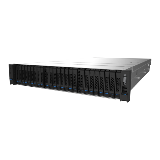
2 Product Specifications 2.1 Introduction Inspur NF5280M5 is a high-end, dual-socket and rack-mounted server, which is designed on the basis of the new generation of Intel® Xeon® scalable processors, to satisfy the requirements of cloud computing, big data, data mining, deep learning and other high-end IT applications. - Page 12 2.5”×24 Configuration (i.e. Full Configuration) ● 2.5”×24 Configuration (i.e. Full Configuration) ● Supports 24 * 2.5" SAS/SATA/SSD/NVME drive in the front, as shown in the figure below. Supports 24 front 2.5” SAS/SATA/SSD/NVME HDDs, as shown in the figure below. Figure 1-1 3.5”×12 Configuration (i.e.
-
Page 13: Features And Specifications
Product Specifications 2.2 Features and Specifications Table 2-1 Processor Two Skylake or Cascade Lake Intel® Xeon® scalable processors (supports up to Processor Type two 205W processors) Socket Chipset Chipset Type C622, C624 Memory Memory Type RDIMM, LRDIMM, NVDIMM, Apache Pass Memory Slot Qty. -
Page 14: Compatible Peripherals - Aoc Cables
External Storage Drive Optical Drive Supports external USB drive T-flash Card Supports built-in TF card Power Single/dual power supply/supplies of 550W/800W/1300W/1600W and above Specifications output power; 1+1 redundancy; 2 power modules; Supports PMBus power supply; Node Manager 4.0 function Power Input Please refer to the power input on the nameplate label of the host Physical 800-length packing box: 651 width ×... -
Page 15: Power Efficiency
Product Specifications 2.4 Power Efficiency Table 2-3 Efficiency Efficiency Rated @10% @20% @50% @100% @50% Level Power Load Load Load Load Load 0.98 550W 0.98 800W Platinum 0.98 1300W 0.98 1600W 2000W 0.98 0.98 800W Titanium 1300W 0.98 Table 2-4 EU Regulation 2019/424 High-end performance Low-end performance... - Page 16 Table 2-5 High-end Low-end (i) List of components for additional power allowance performance performance configuration configuration 1 socket: 10 × Perf CPU W 95.55W 13.23W CPU Performance 2 socket: 7 × Perf CPU W Additional PSU 10 W per PSU HDD or SSD 5.0 W per HDD or SSD Additional memory...
-
Page 17: Component Identification
Component Identification 3 Component Identification 3.1 Front Panel Components 2.5” 24 Drive Bays × ● Figure 3-1 Table 3-1 Item Description Front control panel buttons and LEDs Quick release lever Drive bays VGA port USB3.0 port USB2.0 + LCD port 2.5”... - Page 18 Item Description Table 3-2 Front control panel buttons and LEDs Item Description Quick release lever Front control panel buttons and LEDs HDD bays Quick release lever Drive bays VGA port VGA port USB3.0 port USB3.0 port USB2.0 + LCD port USB2.0 + LCD port 3.5”...
- Page 19 Component Identification Front Control Panel Buttons and LEDs ● Figure 3-7 Table 3-4 Item Description Status & Interpretation Steady green: Power on state Power button Steady orange: Standby state Long press 4s to force a shutdown Turn on/off UID (blue) UID│RST button Long press 6s to force a reset Off: Normal...
-
Page 20: Rear Panel Components
Drive Tray LEDs ● Figure 3-8 Table 3-5 Item Description Status & Interpretation Steady green: Normal Activity status LED Flashing green: Read and write activity Steady red: A failure occurs Fault alarm LED Steady blue: Disk positioning Steady purple: RAID rebuilding 3.2 Rear Panel Components Figure 3-9... - Page 21 Component Identification Figure 3-10 Table 3-6 Item Description Instruction PCIE slots (CPU0) For installing the riser card PCIE slots (CPU0/1) For installing the riser card PCIE slots (CPU1) For installing the riser card For installing the 2.5” drive module 2.5” drive bays MLAN port Management LAN port VGA port...
-
Page 22: Motherboard Components
GPU2 GPU1 GPU3 3.3 主板布局 3.3 Motherboard Components Figure 3-11 Table 3-6 Item Description DIMM slots (CPU0) CPU0 DIMM slots (CPU1) Motherboard handles (2) CPU1 System fan connectors (4) Front HDD backplane power connectors (3) Front control panel connector GPU power connectors (4) Rear HDD backplane power connectors (2) NVME connectors (4) PSU1 connector... - Page 23 Component Identification Item Description OCP_A connector I2C connectors (7) NCSI connector SSATA connector OCP_C connector SYS_IF_SLOT UID│RST button BMC_RST button PCIE1_CPU0/1 connector BMC_IF_SLOT SATA connectors (2) COM port USB3.0 ports (2) VGA port MLAN port PCIE0_CPU0 connector CLR_CMOS VGA+USB ports (Front control panel) USB3.0 ports (2) TPM connector Motherboard Jumper Introduction...
-
Page 24: Operations
4 Operations 4.1 Power up the Server Insert the power cord plug, then press the Power Button. 4.2 Power down the Server WARNING: To reduce the risk of personal injury, electric shock, or damage to the equipment, remove the power cord to remove power from the server. The front panel Power Button does not completely shut off system power. -
Page 25: Remove The Access Panel
Operations Figure 4-1 After performing the installation or maintenance procedure, slide the server back into the rack, and then push the server firmly into the rack to secure it in place. WARNING: To reduce the risk of personal injury, be careful when sliding the server into the rack. -
Page 26: Install The Access Panel
CAUTION: For proper cooling, do not operate the server without the access panel, air baffle, or fan installed. If the server supports hot-plug components, minimize the amount of time the access panel is open. To remove the component: Power down the server if performing a non-hot-plug installation or maintenance procedure. Extend the server from the rack. -
Page 27: Install The Pcie Riser Cage
Operations Extend the server from the rack. Remove the access panel. Remove the PCIE riser cage. Figure 4-5 4.8 Install the PCIE Riser Cage Power down the server. Extend the server from the rack. Remove the access panel. Install the PCIE riser cage. Install the access panel. - Page 28 X8x3 riser card (The slot at the bottom is the X8+X1 slot, which supports both X8 card ● and X8+X1 card.) Figure 4-7 X16+X8 riser card (The slot at the bottom is the X8+X1 slot, which supports both X8 ● card and X8+X1 card.) Figure 4-8 X16 riser card...
-
Page 29: Remove The Air Baffle
Operations 4.9 Remove the Air Baffle CAUTION: For proper cooling, do not operate the server without the access panel, air baffle, or fan installed. If the server supports hot-plug components, minimize the amount of time the access panel is open. Power down the server. -
Page 30: Ssd Option
4.11 M.2 SSD Option Power down the server. Extend the server from the rack. Remove the access panel. Remove the corresponding node. Remove the screw that secures the M.2 riser card to the motherboard, and remove the M.2 riser card vertically. Figure 4-12 Remove the screw that secures the M.2 riser card to the bracket. -
Page 31: Ocp/Phy Card Option
Operations Figure 4-14 4.12 OCP/PHY Card Option Power down the server. Extend the server from the rack. Remove the access panel. Remove the corresponding node. Remove the OCP/PHY card vertically as shown below, and replace it with a new one. Figure 4-15... -
Page 32: Setup
Leave a minimum clearance of 121.9 cm (48 in) from the back of the rack to the back of another rack or row of racks. Inspur Servers draw in cool air through the front door and expel warm air through the rear door. Therefore, the front and rear rack doors must be adequately ventilated to allow ambient room air to enter the cabinet, and the rear door must be adequately ventilated to allow the warm air to escape from the cabinet. - Page 33 Setup adequate airflow (equivalent to the required 64 percent open area for ventilation). • Side—The clearance between the installed rack component and the side panels of the rack must be a minimum of 7 cm (2.75 in). 5.1.2 Temperature Requirements To ensure continued safe and reliable equipment operation, install or position the system in a well-ventilated, climate-controlled environment.
-
Page 34: Rack Warnings
Because of the high ground-leakage currents associated with multiple servers connected to the same power source, Inspur recommends the use of a PDU that is either permanently wired to the building’s branch circuit or includes a nondetachable cord that is wired to an industrial-style plug. -
Page 35: Identifying The Contents Of The Server Shipping Carton
Setup • The leveling jacks are extended to the floor. • The full weight of the rack rests on the leveling jacks. • The stabilizing feet are attached to the rack if it is a single-rack installation. • The racks are coupled together in multiple-rack installations. •... -
Page 36: Installing The Server Into The Rack
5.6 Installing the Operating System To operate properly, the server must have a supported operating system installed. For the latest information on supported operating systems, refer to the Inspur website (http://www.inspur.com/eportal/ui?pageId=2317460). Method to install an operating system on the server:... - Page 37 Setup Load the operating system into a USB disk, boot the server through the USB disk to install the OS. This process may require you to obtain additional drivers from the Inspur website (http://www.inspur.com/eportal/ui?pageId=2317460).
-
Page 38: Hardware Options Installation
6 Hardware Options Installation 6.1 Introduction If more than one option is being installed, read the installation instructions for all the hardware options and identify similar steps to streamline the installation process. WARNING: To reduce the risk of personal injury from hot surfaces, allow the drives and the internal system components to cool before touching them. - Page 39 Hardware Options Installation Step 1: Align the Clip’s triangle mark with the CPU’s corner mark, and then assemble the Clip and CPU together. Figure 6-1 Step 2: Align the heatsink position marked by “1” with the Clip’s triangle mark, vertically align the mounting holes on the heatsink with those on the Clip, and assemble the heatsink and Clip together.
-
Page 40: Memory Option
Figure 6-3 Notes: ● It is required to coat thermal grease evenly onto the contact position between CPU heatsink and CPU. ● During fixing CPU heatsink, it is required to fasten bolts according to the sequence accordingly. 6.3 Memory Option IMPORTANT: RDIMMs and LRDIMMs can not be mixed. - Page 41 Hardware Options Installation ● DIMM population guidelines: Only DIMMs of the same type could be used in the same machine. Detailed DIMM population and combination principles are as follows: One-CPU, DIMM population guidelines: Figure 6-5...
- Page 42 Dual-CPU, DIMM population guidelines: Figure 6-6 Step 1: Open the lock tabs on both ends of the DIMM slot. Step 2: Align the bottom key with the receptive point on the slot, press both ends of the DIMM with your thumbs. Insert the DIMM into the slot completely, and the lock tabs will automatically secure the DIMM, locking it into place.
-
Page 43: Hot-Plug Hdd Option
Hardware Options Installation 6.4 Hot-plug HDD Option CAUTION: For proper cooling, do not operate the server without the access panel, baffles, expansion slot covers, or blanks installed. If the server supports hot-plug components, minimize the amount of time the access panel is open. 1.Determine the status of the hard disk drive from the hot-plug HDD LED. -
Page 44: Redundant Hot-Plug Power Supply Option
Step 3: Use four screws to fix the HDD into the tray. Figure 6-10 Step 4: Install the HDD into the chassis, and lock the lever firmly. 6.5 Redundant Hot-plug Power Supply Option CAUTION: To prevent improper cooling and thermal damage, do not operate the server unless all bays are populated with either a component or a blank. -
Page 45: Expansion Board Option
Hardware Options Installation Figure 6-12 Connect the power cord to the power supply. Route the power cord through the power cord anchor or cable management arm. Reposition the cable management arm into the operating position. Connect the power cord to the power source. Verify that the corresponding power supply LED is green. -
Page 46: Air Baffle Option
Figure 6-13 Pull out the expansion card in the arrow direction, and replace it with a new expansion card. Figure 6-14 6.7 Air Baffle Option CAUTION: For proper cooling, do not operate the server without the access panel, baffles, expansion slot covers, or blanks installed. If the server supports hot-plug components, minimize the amount of time the access panel is open. - Page 47 Hardware Options Installation Remove the access panel. Remove the air baffle vertically to replace it with a new one. Figure 6-15...
-
Page 48: Cabling
7 Cabling Cable routing (blue) between the backplane and SAS/RAID card; Cable routing (red) between the backplane and motherboard. Figure 7-1 CAUTION: Please route the cables according to the purchased machine configuration. -
Page 49: Bios Setup
Power on the server. The system will then start to boot. When the following content appears below Inspur logo on the screen: “Press <DEL> to SETUP or <TAB> to POST or <F11> to Boot Menu or <F12> to PXE Boot.” Press DEL key. When “Entering Setup …” appears in the lower right corner of the screen, it will enter the BIOS setup soon. - Page 50 Boot Mode (UEFI Mode/Legacy Mode). Set the Option ROM execution mode of Network, Storage, Video OPROM Policy and Other PCI devices, as shown in the following figure. At present, Inspur Purley platform servers are set to UEFI Mode by default. Compared...
- Page 51 BIOS Setup with Legacy mode, UEFI mode has many advantages: it supports boot from the GPT disk, supports IPv6/IPv4 PXE boot, and provides UEFI Shell environment. This option can be set according to customer’s demand. If the Boot Mode is set to Legacy Mode, the Option ROM execution mode of Network, Storage, Video OPROM Policy and Other PCI devices must be set to Legacy.
- Page 52 Figure 8-3 8.1.4 View CPU Information Login to the BIOS interface, select “Processor -> Processor Configuration -> Processor Information”, and press Enter to display the CPU detailed information, as shown in the following figure. Figure 8-4 8.1.5 View Memory Information Login to the BIOS interface, select “Processor ->...
- Page 53 BIOS Setup Topology”, and press Enter to display the manufacturer, speed, capacity and other information of the memories in position, as shown in the following figure. Figure 8-5 8.1.6 View HDD Information and RAID Configuration 8.1.6.1 View HDD Information Login to the BIOS interface, select “Chipset -> PCH SATA Configuration/PCH sSATA Configuration”, and press Enter to display the HDD information of the current onboard SATA ports or sSATA ports, as shown in the following figures.
- Page 54 Figure 8-7 8.1.6.2 HDD RAID Mode Settings Set the SATA Mode Option to [RAID], press F10 to save the setting, and the system reboots. When Boot Mode is set to UEFI mode, in the BIOS Setup Advanced interface, there will be the Intel(R) RSTe SATA Controller menu, as shown in the following figure.
- Page 55 BIOS Setup Figure 8-9 Create RAID volume. Select Create RAID Volume option, and press Enter, as shown in the following figure. Figure 8-10 Table 8-2 Create RAID Menu Instruction Table Interface Parameters Function Description Please enter a volume name less than 16 characters without containing any special Name characters.
- Page 56 Delete RAID volume. Select a created RAID Volume, press Enter. Select “Delete”, there will be a prompt. To delete the volume, select “Yes” and press Enter; to cancel the deletion, select “No” and press Enter. Figure 8-11 Figure 8-12 Figure 8-13 When Boot Mode is set to Legacy, a prompt “Press <CTRL-I>...
- Page 57 BIOS Setup Figure 8-14 After entering SATA RAID configuration interface, it will display the main menu list, the information (HDD ID, HDD type, HDD capacity, volume member or not) of HDDs connected to SATA controller, and the existed RAID volumes information (including volume ID, name, RAID level, capacity, status, bootable or not).
- Page 58 Create RAID Volume menu. After entering SATA RAID configuration interface, you could use up and down arrow keys to select this menu, and then press Enter to enter the Create RAID Volume menu, or directly input the number before the menu to enter the Create RAID Volume menu.
- Page 59 BIOS Setup Delete RAID Volume menu. After entering Delete RAID Volume menu, press [DEL] to delete the selected RAID volume, and the system will prompt “ALL DATA IN THE VOLUME WILL BE LOST! Are you sure you want to delete “Volume0*”? (Y/N)”. To delete this RAID volume, please enter “Y”, to cancel the deletion, please enter “N”.
- Page 60 mask selected disks as Spare? (Y/N)”, enter “Y” or “N” according to the prompt. It is to be noted that all data on this disk will be lost as the spare disk. Figure 8-19 Exit menu. Select Exit menu through up and down keys, or press ESC to exit SATA RAID configuration interface, as shown in the following figure.
- Page 61 BIOS Setup Figure 8-21 Figure 8-22 8.1.7.2 BMC Network Settings Take BMC Sharelink port as an example to introduce the settings of BMC IPv4 network parameters, as shown in the following table. BMC Network Configuration Instruction Table...
- Page 62 Table 8-6 Interface Parameters Function Description Default Value Set the way to get BMC network parameters, options include: Get BMC Sharelink / Do Nothing Do Nothing Dedicated Parameters Auto Manual Configure BMC network status parameters. When Get BMC Dedicated Parameters is set to [Manual], this option will be displayed.
- Page 63 BIOS Setup Figure 8-25 If the setting succeeds, the system prompts “Set Static BMC Station IP OK!!!” Press Enter to confirm, and the IP will take effect immediately. If the setting fails, the system prompts “Set Static BMC Station IP Fail!!!” If the IP does not change, the system prompts “Static BMC Station IP Not Change!!!”...
- Page 64 Figure 8-27 After pressing Enter to confirm, the following interface will stay for 30s, please wait patiently. Figure 8-28 After the dynamic network takes effect, the system will prompt “Get Dynamic BMC Dhcp Success!!”, and the interface will be shown as the following figure. Figure 8-29 Note: Please make sure that the BMC management port is connected to the network when you...
-
Page 65: Bios Parameter Description
BIOS Setup The options that take effect immediately in the BIOS Setup interface are implemented by calling the Callback function. Callback functions are only called when the options in the BIOS Setup interface are changed. Otherwise, the function will not take effect. For example, if you want to automatically get BMC parameters again, you need to set Get BMC Sharelink Parameters to [Do nothing] or [Manual], then set to [Auto], the function will take effect. - Page 66 BMC Firmware Version BMC Firmware version ME Firmware Version ME Firmware version Access Level Current access level CPU Information Display the current CPU’s type, PCH SKU, RC version information. Memory Information Display the current total memory capacity and frequency information. Display and set system date.
- Page 67 BIOS Setup PCI Subsystem Settings PCI subsystem settings Network Stack Configuration Network stack configuration CSM Configuration CSM configuration NVMe Configuration NVMe configuration PCH 10GBE PHY Card Configuration PCH 10GBE PHY card configuration iSCSI Configuration iSCSI configuration Intel(R) Virtual RAID on CPU Intel NVMe virtual RAID configuration Intel®...
- Page 68 8.2.2.2 Super IO Configuration Super IO Configuration interface is used to set the options related with I/O chip. Figure 8-33 Table 8-10 Super IO Configuration Interface Instruction Table Interface Parameters Function Description Serial port 0 configuration, the configuration interface provides this serial port’s on-off control and resource allocation control.
- Page 69 BIOS Setup Figure 8-34 Table 8-11 Serial Port 0 Configuration Interface Instruction Table Interface Parameters Function Description Default Value Serial port 0 on-off settings. Options include: Serial Port Enabled Enabled Disabled Select the optimal setting according to the demand. Options include: Auto Change Settings...
- Page 70 Figure 8-35 Table 8-12 Serial Port Console Redirection Interface Instruction Table Interface Parameters Function Description Default Value Serial port console redirection on-off settings. Options include: Console Redirection Disabled Enabled Disabled Console Redirection Settings Serial port console redirection parameter settings ---- 8.2.2.4 Console Redirection Settings When the Console Redirection is set to [Enabled], the Console Redirection Settings menu will be opened.
- Page 71 BIOS Setup Table 8-13 Console Redirection Settings Interface Instruction Table Interface Parameters Function Description Default Value Terminal type settings. Options include: VT100 Terminal Type VT100+ ANSI VT-UTF8 ANSI Baud rate settings. Options include: 9600 19200 Bits per second 115200 38400 57600 115200 Serial port data width settings.
- Page 72 8.2.2.5 PCI Subsystem Settings PCI Subsystem Settings interface is used to set the options related with PCI subsystem. Figure 8-37 Table 8-14 PCI Subsystem Settings Interface Instruction Table Interface Parameters Function Description Default Value Above 4G memory access control on-off settings. Options include: Above 4G Decoding Enabled Enabled...
- Page 73 BIOS Setup Table 8-15 Network Stack Configuration Interface Instruction Table Interface Parameters Function Description Default Value Network stack on-off settings. Options include: Enabled Network Stack Disabled Enabled Only this option is enabled, the following options can be displayed and the functions can be set. UEFI Ipv4 PXE support on-off settings.
- Page 74 Table 8-16 CSM Configuration Interface Instruction Table Interface Parameters Function Description Default Value CSM support on-off settings. Options include: CSM Support Enabled Disabled Disabled A20 line control mode settings. Options include: Upon Request GateA20 Active Always Upon Request A20 is an address line, which controls the system how to access the memory space larger than 1MB.
- Page 75 BIOS Setup 8.2.3 Chipset Chipset interface includes the information settings and runtime error logging settings of PCH SATA/sSATA, USB and ME devices. Figure 8-41 Table 8-17 Chipset Interface Instruction Table Interface Parameters Function Description PCH SATA Configuration PCH SATA configuration PCH sSATA Configuration PCH sSATA configuration USB Configuration...
- Page 76 Figure 8-42 Figure 8-43 Table 8-18 PCH SATA Configuration Interface Instruction Table Interface Parameters Function Description Default Value SATA controller on-off settings. Options include: SATA Controller Enabled Enabled Disabled SATA mode settings. Options include: SATA Mode Options AHCI AHCI RAID SATA Port 0~7 SATA port 0 ~...
- Page 77 BIOS Setup PCH sSATA Configuration Interface Instruction Table is omitted here. 8.2.3.2 USB Configuration USB Configuration is used to set the options related with the onboard USB ports. Figure 8-44 Table 8-19 USB Configuration Interface Instruction Table Default Value Interface Parameters Function Description Onboard USB port on-off settings.
- Page 78 Table 8-20 Miscellaneous Configuration Interface Instruction Table Interface Parameters Function Description Default Value Power state settings when restoring on AC power loss. Options include: Restore AC Power Loss Power OFF Power OFF Last State Power ON The maximum page table size settings. Options include: Max Page Table Size For older OS, please select 2MB, otherwise, it may cause a problem.
- Page 79 BIOS Setup ---- Current State Current state ---- Error code ME FW error code Recovery Cause Recovery cause PTT support on-off settings. Options include: Disabled PTT Support Enabled Disabled 8000 Altitude Altitude settings MCTP bus owner is located in PCIe: [15:8] bus, [7:3] MCTP Bus Owner device, [2:0] function.
- Page 80 8.2.4 Processor Processor interface is used to set the options related with the processor and memory. Figure 8-48 Table 8-23 Processor Interface Instruction Table Interface Parameters Function Description Processor Configuration Processor configuration Common Configuration Common configuration UPI Configuration UPI configuration Memory Configuration Memory configuration IIO Configuration...
- Page 81 BIOS Setup Figure 8-49 Table 8-24 Processor Configuration Interface Instruction Table Interface Parameters Function Description Default Value Processor information submenu, the processor’s detailed Processor Information ---- information CPU core settings. Input the number of CPU cores you want to enable. In the Help information, it will display the Active Cores effective values you can set and the maximum number of physical cores according to the current CPU usage.
- Page 82 Safe mode extension on-off settings. Options include: Enabled Disabled Disabled Hardware prefetcher on-off settings. Options include: Enabled Disabled Before CPU processing instructions or data, it will prefetch Hardware Prefetcher Enabled these instructions or data from memory to L2 cache, to shorten the amount of time that reading memory takes, to help eliminate potential bottlenecks and to improve system performance.
- Page 83 BIOS Setup Figure 8-50 Table 8-25 Common Configuration Interface Instruction Table Interface Parameters Function Description Default Value MMIO high base settings. Options include: MMIO High Base MMIO high granularity size settings. Options include: MMIO High Granularity Size 256G 256G 1024G Numa on-off settings.
- Page 84 Figure 8-51 Table 8-26 UPI Configuration Interface Instruction Table Interface Parameters Function Description Default Value UPI Status UPI status submenu, displaying the current UPI link status ---- Degrade precedence settings. Options include: Topology Precedence Feature Precedence Topology Degrade Precedence When the system settings conflict, set it to Topology Precedence Precedence to reduce Feature;...
- Page 85 BIOS Setup Sub NUMA cluster settings. Options include: Auto: Support 1-cluster or 2-clusters according to IMC interleave. Sub NUMA Clustering Disabled Enabled: Support all SNC clusters (2-clusters) and 1-way IMC interleave. Disabled: SNC function not supported. Legacy VGA number settings, the range of effective values is Legacy VGA Socket 0~1.
- Page 86 System promote warnings on-off settings. Options include: Promote Warnings Enabled Enabled Disabled On-off settings of halt on memory training error. Options include: Halt On mem Training Error Enabled Enabled Disabled NVMDIMM data scrambling on-off settings. Options Data Scrambling for include: Enabled NVMDIMM Enabled...
- Page 87 BIOS Setup Figure 8-53 Table 8-28 Memory Map Interface Instruction Table Interface Parameters Function Description Default Value Volatile memory mode settings. Options include: Volatile Memory Mode Auto 1LM memory interleave granularity settings. Options include: 1LM Memory Interleave Granularity Auto Auto 256B Target, 256B Channel 64B Target, 64B Channel IMC interleaving settings.
- Page 88 8.2.4.4.2 Memory RAS Configuration Memory RAS Configuration interface is used to set the options related with the memory RAS feature. Figure 8-54 Table 8-29 Memory RAS Configuration Interface Instruction Table Interface Parameters Function Description Default Value Static virtual lockstep mode on-off settings. Options include: Static Virtual Lockstep Mode Disabled...
- Page 89 BIOS Setup Correctable Error Threshold Correctable error threshold settings SDDC+1 on-off settings. Options include: SDDC Plus One Enabled Disabled Disabled ADDDC sparing on-off settings. Options include: ADDDC Sparing Enabled Disabled Disabled NGN Die sparing on-off settings. Options include: Set NGN Die Sparing Enabled Enabled Disabled...
- Page 90 Table 8-30 IIO Configuration Interface Instruction Table Interface Parameters Function Description Default Value Socket N configuration submenu, used to set the Link speed, Max Payload Size and ASPM of the CPU0’s PCIE SocketN Configuration ---- device, and to display the link status, maximum link and current link speed of the PCIE port.
- Page 91 BIOS Setup Table 8-31 Advanced Power Management Configuration Interface Instruction Table Interface Parameters Function Description CPU P State Control CPU P state control submenu Hardware PM State Control Hardware PM state control submenu CPU C State Control CPU C state control submenu Package C State Control Package C state control submenu CPU-Advanced PM Tuning...
- Page 92 8.2.4.6.2 Hardware PM State Control Hardware PM State Control interface is used to set the options related with the hardware PM state. Figure 8-58 Table 8-33 Hardware PM State Control Interface Instruction Table Interface Parameters Function Description Default Value Hardware P-States is set by OS automatically or not, the default value is decided based on the actual test.
- Page 93 BIOS Setup Figure 8-59 Table 8-34 CPU C State Control Interface Instruction Table Interface Parameters Function Description Default Value Monitor/Mwait support on-off settings. Options include: Monitor/Mwait Support Enabled Enabled Disabled Autonomous core C-state on-off settings. Options include: Autonomous Core C-State Disabled Enabled Disabled...
- Page 94 Figure 8-60 Table 8-35 Package C State Control Interface Instruction Table Interface Parameters Function Description Default Value Package C state settings. Options include: C0/C1 state C2 state C6 (Retention) state Package C State C6 (Non Retention) state C6 (Retention) state No Limit 8.2.4.6.5 CPU-Advanced PM Tuning CPU-Advanced PM Tuning interface is used to set the options related with the CPU power-...
- Page 95 BIOS Setup Table 8-36 Energy Perf BIAS Interface Instruction Table Interface Parameters Function Description Default Value Power performance tuning settings. Options include: Power Performance Tuning OS Controls EPB OS Controls EPB BIOS Controls EPB Power performance management settings. Options include: Performance Balanced Performance Balanced...
- Page 96 Table 8-37 Server Mgmt Interface Instruction Table Interface Parameters Function Description Default Value BMC Self Test Status BMC self-test status ---- BMC Firmware Version Current motherboard’s BMC firmware version ---- FRB-2 timer on-off settings. Options include: FRB-2 Timer Enabled Enabled Disabled FRB-2 timer timeout settings.
- Page 97 BIOS Setup Figure 8-63 Table 8-38 BMC Network Configuration Interface Instruction Table Interface Parameters Function Description Default Value Sharelink Network BMC Sharelink network on-off settings, take effect immediately. Enabled BMC IPv4 Network Configuration BMC IPv4 network configuration ---- BMC IPv6 Network Configuration BMC IPv6 network configuration ---- 8.2.5.1.1 BMC IPv4 Network Configuration BMC IPv4 Network Configuration interface is used to configure the BMC IPv4 management...
- Page 98 Table 8-39 BMC IPv4 Network Configuration Interface Instruction Table Interface Parameters Function Description Default Value Set the method to get the BMC sharelink/ dedicated parameters. Options include: Get BMC Sharelink/Dedicated Do Nothing Do Nothing Parameters Auto Manual Set BMC network status. Options include: Unspecified Configuration Address Source Static...
- Page 99 BIOS Setup Table 8-40 BMC IPv6 Network Configuration Interface Instruction Table Interface Parameters Function Description Default Value Set the method to get the BMC sharelink/dedicated parameters. Options include: Get BMC Sharelink/Dedicated Do Nothing Do Nothing Parameters Auto Manual Set BMC network status. Options include:: Unspecified Configuration Address Source Static...
- Page 100 8.2.5.2.1 Add User Add User interface is used to add a BMC user through BIOS. The addition takes effect immediately, and the user will be added to the BMC user list. Figure 8-67 Table 8-42 Add User Interface Instruction Table Interface Parameters Function Description Default Value User Name...
- Page 101 BIOS Setup immediately, and this user can not login to the BMC Web interface any more. Figure 8-68 Table 8-43 Delete User Interface Instruction Table Interface Parameters Function Description User Name Input the name of user to delete Input the password of user to delete. If the password is correct, it pops User Password up “User Deleted!!!”...
- Page 102 Table 8-44 Change User Settings Interface Instruction Table Interface Parameters Function Description Default Value User Name Input the name of user to modify ---- Input the password of user to modify. Only both the name and User Password password are correct, the following options can be modified. ---- User privilege on-off settings.
- Page 103 BIOS Setup 8.2.5.4 View FRU Information View FRU Information interface displays the BMC FRU information read by BIOS. On each system reboot, BIOS interacts with BMC to keep the FRU information synchronized. It defaults to no password for the BIOS, users can set the password according to the requirement when using the machine.
- Page 104 Figure 8-72 Table 8-47 Security Interface Instruction Table Interface Parameters Function Description Create an administrator password. It must contain uppercase and lowercase Administrator Password letters, special characters and numbers, within 8-20 characters. Create a user password. It must contain uppercase and lowercase letters, User Password special characters and numbers, within 8-20 characters.
- Page 105 BIOS Setup Table 8-48 Boot Configuration Interface Instruction Table Default Value Interface Parameters Function Description Setup prompt timeout settings. Set the time to wait for the Setup Prompt Timeout Setup activate key, and the maximum value is 65535 seconds. Bootup Numlock state on-off settings. Options include: Bootup NumLock State Boot options retry on-off settings.
- Page 106 For BIOS update, you could select to update in UEFI Shell or OS. 8.3.1 Update BIOS in UEFI Shell When Inspur Logo appears on the screen during system booting, there is a prompt “Press <DEL> to SETUP or <TAB> to POST or <F11> to Boot Menu or <F12> to PXE Boot” below.
- Page 107 BIOS Setup When there is no change in ME part, execute the command to update 16M BIOS: AfuEfix64.efi BIOS.bin /b /p /n /x /k /l, and the process is as shown in the following figure. After the update is complete, it is recommended to power cycle the system. Figure 8-77 If there are any changes in ME part, execute the command to update 32M ME+BIOS: AfuEfix64.efi BIOS.bin /b /p /n /x /k /l /me, and the process is as shown in the following...
- Page 108 Figure 8-78 Note: After the update is complete, please power off the machine, confirm that there is no residual electricity on the motherboard, and then power it on. 8.3.2 Update BIOS in Linux There are 32bit and 64bit Linux OS afulnx tools. Taking Linux 64bit OS as an example, use the afulnx_64 tool to enter the directory containing afulnx_64 tool.
- Page 109 BIOS Setup Figure 8-79 If there are any changes in ME part, execute the command to update BIOS and ME simultaneously: ./afulnx_64 BIOS.bin /b /p /n /x /k /l /me, as shown in the following figure. Figure 8-80 Notes: 1. For Linux system, it needs to run the afulnx_64 tool as root. 2.
-
Page 110: Bmc Settings
9 BMC Settings 9.1 Introduction This section describes the functional specifications for the Baseboard Management Controller (BMC). It also describes the features’ detail information. This document is written for software developers, system integrators, testers and server management users. 9.2 Server System Overview BMC is an independent system of host server system. - Page 111 BMC Settings 9.2.2 Integrated BMC Hardware ASPEED AST2500 is the processor of server management subsystem, based on ARM1176JZF-S 32-bit RISC CPU microcontroller. The following functions are integrated into the component: ● Baseboard Management Controller (BMC) with peripherals ● Server-class Super I/O (SIO) ●...
-
Page 112: Ipmi2.0
and the host can boot from this remote media via redirection over the USB interface. 9.3 IPMI2.0 9.3.1 Channel ID Assignment for Each Interface Table 1 Channel ID Assignment for Each Interface Channel ID Interface Support Sessions Primary IPMB Secondary IPMB Third IPMB Primary LAN Secondary LAN... - Page 113 BMC Settings 9.3.5 IPMI Commands Tables below define the IPMI commands supported by the BMC. IPMI SPEC standard command: Table 3 IPMI NetFn NetFn Chassis Storage Transport Bridge Value 0x06 0x00 0x04 0x0A 0x0C 0x02 Table 4 IPMI Spec Standard Command IPMI Device “Global”...
- Page 114 Get BT Interface Capabilities Get System GUID Set System Info Parameters Get System Info Parameters Get Channel Authentication Capabilities Get Session Challenge Activate Session Set Session Privilege Level Close Session Get Session Info Get AuthCode Set Channel Access Get Channel Access Get Channel Info Command Set User Access Command Get User Access Command...
- Page 115 BMC Settings Set Power Restore Policy Chassis Set Power Cycle Interval Chassis Get System Restart Cause Chassis Set System Boot Options Chassis Get System Boot Options Chassis Get POH Counter Chassis Event Commands Set Event Receiver Get Event Receiver Platform Event (a.k.a. “Event Message”) PEF and Alerting Commands Get PEF Capabilities Arm PEF Postpone Timer...
- Page 116 Get SDR Repository Allocation Info Storage Reserve SDR Repository Storage Get SDR Storage Add SDR Storage Partial Add SDR Storage Delete SDR Storage Clear SDR Repository Storage Get SDR Repository Time Storage Set SDR Repository Time Storage Enter SDR Repository Update Mode Storage Exit SDR Repository Update Mode Storage...
- Page 117 BMC Settings Callback Transport Set User Callback Options Transport Get User Callback Options Transport Set Serial Routing Mux Transport SOL Activating Transport Set SOL Configuration Parameters Transport Get SOL Configuration Parameters Transport Command Forwarding Commands Forwarded Command Bridge Set Forwarded Commands Bridge Get Forwarded Commands Bridge...
-
Page 118: Management Web Gui
9.4 Management Web GUI HTTPS (Port 443) is supported to access Web GUI. HTTP is disabled by default, users can enable it by IPMI OEM CMD. The Management Web GUI provides management interface for users to view the system information, system event and status, and to control the managed server. The Web GUI is supported by following browsers: Table 5 Supported Browsers Client OS... - Page 119 BMC Settings Step 2 In the WEB login interface, enter the user name and password, click the “Login” button to enter the home page, as the figure shows. Figure 9-3 Web Login When you forget password, you can click “Forgot Password?” link to get a new password by Email.
- Page 120 Controller RAID/SAS controller asset info and running state Physical Drives Physical drives lists, asset info and running state Storage Logical Drives Logical drives lists, asset info and running state Enclosure Topology of RAID/SAS controller HTML5 KVM Console Redirection Java KVM Console Redirection Setting Remote Control Display UID status...
-
Page 121: Snmp
BMC Settings Local Users setting User Administration BMC System Administrator Directory Group setting LDAP setting Security AD setting Dual Image Set image start order configuration Administration BMC Firmware Upgrade BMC firmware Update BIOS Firmware Upgrade BIOS firmware Update CPLD Update Upgrade CPLD Restore Factory Restore BMC settings to factory defaults... -
Page 122: Smash-Lite Cli
snmptrap Fault snmptrapd Detect snmpget snmpd snmpset Figure 9-4 SNMP Schematic 9.6 Smash-Lite CLI BMC supports Smash-Lite CLI, users can login to BMC via SSH and enter Smash-Lite CLI. And it supports ipconfig, sensor, fru, chassis, user, mc, fan, psu, id, diagnose commands, as the figure shows. - Page 123 BMC Settings sensor ● Figure 9-7 Sensor ● Figure 9-8 Fru chassis ● Figure 9-9 Chassis user ● Figure 9-10 User...
- Page 124 • Figure 9-11 MC ● Figure 9-12 Fan ● Figure 9-13 Psu ● Figure 9-14 Id...
-
Page 125: System Information And State
BMC Settings diagnose ● Figure 9-15 Diagnose 9.7 System Information and State Login WEB GUI, go to page “Information-> System Information”, this page displays information and health status of main components of platform, including CPU, Memory, PCIE Device, Network, Hard Disk Backplane, Power Supply Unit, Fan, Temperature, and Voltage. - Page 126 Table 7 CPU Information Attribute Value CPUx, x is CPU No., starting from 0. Processor Name Product Model Normal State Warning State Processor Status Critical State State unavailable or current power is off The State depends on CPUx_Status sensors. Processor Speed (MHz) Processor Speed Core x/y, x is Current Used Core Number, y is All Core Number.
- Page 127 BMC Settings 9.7.3 Device Inventory Go to table “Device Inventory” in System Information page. Figure 9-18 PCIE Information Table 9 PCIE Information Attribute Value x, x is PCIE device number, starting from 0. Slot on Board Onboard slot number where device is located. Slot on Riser Riser slot number where the device is located.
- Page 128 Table 10 BMC Adapter Attribute Value x, x denotes the device number. Name eth0 or eth1 MAC Address Mac Address IP Address IP Address Table 11 System Adapter Attribute Value x, x denotes the device number. Present Present Absent Location Location Port Number Port Number...
- Page 129 BMC Settings Table 13 Hard Disk Attribute Value x, x denotes the device number. Present Present Absent Front/Rear Hard disk location, front or rear Hard Disk Backplane Hard Disk Backplane Number Normal State Error Error State Absent Locating Locate Absent or Non Locate Rebuilding Rebuild Absent or Non Locate...
- Page 130 Table 15 Power Supplies Attribute Value PSUx, x denotes the power supply number. Present Present Absent Error Status, depends on PMBus Status Word Status command, 97h. MFR ID Manufacture ID MFR Model Manufacture Model Serial Number Serial Number Rated Power (W) Rated Power FW Version Firmware Version...
- Page 131 BMC Settings Table 16 Fan Information Attribute Value FANx_y, x denotes FAN or FAN group number, y denotes FAN number in group. Present Present Absent Normal State Status Critical State State unavailable or current power is off Speed (rpm) Speed in rpm Duty Ratio (%) Speed in duty Fan Power (Optional)
- Page 132 Note : Threshold value N/A means not configured. 9.7.9 Voltage Go to table “Voltage” in System Information page. Figure 9-24 Voltage Information Table 18 Voltage Information Attribute Value Sensor Sensor Name Normal State Warning State Status Critical State State unavailable or current power is off Reading (V) Temperature Reading Lower NRT (V)
- Page 133 BMC Settings 9.7.10 Global Running State Login WEB GUI, go to first page “Overview”, main devices’ running states are displayed. Figure 9-25 Global Running State Table 19 System Running State Device State Denotation Power On Current Power Status Power Off UID LED On UID Status UID LED Off...
- Page 134 PSU Healthy state: Normal State Power Supply Unit Warning State – One or more PSUx_Status warning Critical State – One or more PSUx_Status critical Power Off PSU Redundant state: Normal State Power Redundancy Warning State –PSU_Redundant Sensor warning Critical State – PSU_Redundant Sensor critical Power Off Voltage Sensor state: Normal State...
-
Page 135: Device State Monitor And Diagnostic
Chassis Part Number: ** Chassis Serial Number: ** Board Information Area Format Version: * Language: * Manufacture Date Time: weekday/month/day/year Board Manufacturer: Inspur Board Information Board Product Name: ***** Board Serial Number: ** Board Part Number: ** Board Extra: *****... - Page 136 Sensor type. ● Temperature: BMC monitors temperature of system components like CPU, PCH, DIMM, PSU and HSBP, and monitors Inlet/Outlet temperatures. ● Voltage: System P12V, P5V, P3V3, PVNN, PVDDQ, PVCCIO, PVCCIN. ● Fan Speed: System fan. ● Power Consumption: BMC monitors Total Power, CPU Power, Memory Power, PSU Input Power.
- Page 137 BMC Settings If sensor event type is generic, please refer to Generic Event/Reading Type Code table in IPMI Specification, Version 2.0. If sensor event type is sensor-specific, please refer to Sensor Type Code tables in IPMI Specification, Version 2.0. ● Assertion/De-assertion Assertion and de-assertion indicators reveal the type of events this sensor generates.
-
Page 138: Logs
9.8.5 PSU Table 25 PSU Health State Monitored State Level Related Model Present Info SDR/SEL/Blackbox Power Supply Failure Critical SDR/SEL/Blackbox Predictive Failure Warning SDR/SEL/Blackbox Power Supply AC lost Critical SDR/SEL/Blackbox 9.9 Logs Logs provide the history record of main devices state changes, used for fault diagnostic. 9.9.1 System Event Log BMC provides the ability to record IPMI sensor based event history. - Page 139 BMC Settings Figure 9-26 System Event Log Table 26 SEL Attributes Event ID Description Time Stamp Event generate time Severity Event error level, include Error, Warning, Information Sensor Name Sensor Name, locate the device Sensor Type Sensor Type defined in IPMI2.0 Description Event details 9.9.2 Audit Log...
- Page 140 Figure 9-27 BMC Audit log Table 27 Audit Log Attributes Event ID Description Time Stamp Event generate time Host Name BMC host name Description Event details 9.9.3 Blackbox Log BMC supports blackbox function used to record some details when event occurred. ●...
-
Page 141: Event Alerting
BMC Settings 9.9.4 System Serial Log Refer to section “Serial over LAN (SOL) and System Serial Log Recording”. 9.10 Event Alerting BMC supports SNMP Trap and SMTP email alerts. 9.10.1 SNMP Trap Alert BMC supports SNMP Trap. Users open trap receiver and set trap destination IP in BMC Web GUI. - Page 142 Figure 9-30 Event Filter Step 3 Set alert type and destination. Firstly enable one of three items. If SNMP selected, user should set destination to his IP, if Email selected, user should set LAN Channel to dedicated or shared network, then set destination to a user configured email. Figure 9-31 Alert Policy Configure 9.10.2 SMTP Email Alert SMTP (Simple Mail Transport Protocol, defined in RFC821) email alert is supported.
-
Page 143: Diagnostics
BMC Settings Step 2 Configure destination email for related user. Figure 9-33 Email Settings Step 3 Set destination in Figure “Alert Policy Configure” like SNMP Trap Alert Step 3. 9.10.3 Syslog Syslog supports on/off, supports log level filtering, supports 4 receiving targets and every target can configure the receiving server address (IPv4 / IPv6 / FQDN), port number, log type, enable status and send test information. - Page 144 9.11.1 BIOS Post Code (Port 80h) BIOS sends Post code to IO port 80h. If there are any errors during power on, the last post code is on port 80h. BMC is able to trace post code via port 80h to figure out the cause of issue happened.
-
Page 145: Bmc Self Recovery
BMC Settings 9.11.3 BMC Watchdog for System Software watchdog can be used for a number of system timeout function by system management or by BIOS. If software watchdog is triggered, the following actions are available. ● System Reset ● System Power Off System Power Cycle ●... -
Page 146: Led
● When entering the flash mode, set watchdog time to 20 mins, if timeout BMC will reset automatically. When flashing image starts, the watchdog will update to 20 mins, if timeout BMC will reset automatically. 9.12.2 Software Watchdog BMC regularly detects the working status of internal services. When the progress is abnormal, BMC will restart the corresponding service: IPMI Server ●... - Page 147 BMC Settings IP address manual setting, and MAC address is stored in the EEPROM. ● Support VLAN. ● By default, IPMI LAN channels are assigned as below: Table 29 BMC LAN Interface Channel ID Interface Support Sessions Primary LAN (eth1) Secondary LAN (eth0) ●...
- Page 148 Default Interface: Select the default network interface. Auto Configuration: Enable/Disable Auto Configuration. If Auto Configuration is disabled, then interface service can be configured via IPMI command. If Auto Configuration is enabled, then all services will restart automatically. Bond Mode: Display the current bond mode (This field is read-only). 9.14.3 NCSI NC-SI (“Network Controller Sideband Interface”) is an electrical interface and protocol defined by the Distributed Management Task Force (DMTF), which enables the connection...
-
Page 149: Users
BMC Settings Supported NCSI cards on PURLEY platform, include onboard NIC, PHY card, OCP A/B/C card, Inspur designed and NCSI-supported PCIE NIC. Different projects support one or more NCSI cards. Login Management Web GUI, enter “BMC Settings > BMC Shared NIC Switch”, as shown below. - Page 150 ● SNMP user is used for SNMP Get/Set. ● Uboot password is used to access BMC Uboot by BMC Diagnose Serial Cable. 9.15.1 IPMI/WEB/SSH Unified User BMC supports IPMI 2.0 user model. Unified user could be created by IPMI CMD or Web GUI. ●...
- Page 151 BMC Settings ● If enabled, you need change password in expiration time. If password will be expired less than 15 days, when you login Web GUI, Web will alert “Days until password expires: xx”. ● If password expired, you need disable this function in HOST OS by OEM IPMI CMD. Password Expiration is only supported in Web GUI.
- Page 152 - No more than 64 characters. 9.15.3 SNMP User SNMP user is used to support SNMP Get/Set, could be created by IPMI CMD or Web GUI. Default Read Only community: inspur@0531. ● ● For security, SNMP V1/V2c is non-secure, default Disabled.
- Page 153 BMC Settings not need to authenticate user and password, because he will get the highest privilege if someone accesses the HOST OS. So if the user forgets password or password expires, this is a way to change password or disable password security rules. Please refer to IPMI 2.0 Spec, Appendix G - Command Assignments.
- Page 154 System Event Log BMC System Audit Log Black Box Log Logs Event Log Setting BMC System Audit Log Setting BMC Self-inspection Result BMC Recovery Fault Diagnosis Capture Screen Host POST Code User Administration Security Dual Image Configuration Dual Firmware Update Administrator BIOS FW Update CPLD Update...
- Page 155 BMC Settings 9.15.5.3 User Privilege for CLI (Access by SSH) Table 33 Sub CMD ipconfig sensor chassis user password register diagnose diaglog Note N = No Access Privilege level of Unified User U = User Privilege level of Unified User O = Operator Privilege level of Unified User A = Administrator Privilege level of Unified User YES = Support...
-
Page 156: Protocols And Ports
9.16 Protocols and Ports BMC supports network connection manager library to configure networking services configuration in run-time. RCMP+, HTTP/HTTPS, KVM, CD-MEDIA, FD-MEDIA, HD-MEDIA, SSH, SNMP services are supported so far. Users can enable or disable theses services, configure communication port, session timeout value of the service and the maximum number of allowed sessions for the services. -
Page 157: Time And Ntp
BMC Settings Table 35 Fixed Protocols Service Usage State Port TCP/UDP smux SNMP Multiplexer Enable srvloc Sever location Enable TCP, UDP DHCP V6 Client DHCP V6 Client Enable Websockify KVM on HTML5 Enable 9666 Websockify Virtual Media on HTML5 Enable 9999 9.17 Time and NTP BMC supports that system describes instants in time. -
Page 158: Bios And Bmc
9.18 BIOS and BMC BIOS and BMC cooperate very closely in the server. BIOS uses IPMI command to communicate with BMC by means of KCS interface on LPC bus. BIOS provides following features to BMC. Sync Host RTC time with BMC by “Set SEL Time Command”. ●... - Page 159 BMC Settings 9.18.1 BIOS Setup Options BMC supports BIOS Setup Option getting and setting. ● BIOS sends BIOS Setup Options to BMC When BIOS POST completes. Users can use IPMI OEM CMD to change setup option value. BIOS will update setup option ●...
-
Page 160: Storage
Figure 9-43 Boot Option 9.19 Storage Server storage subsystem generally consists of RAID and SAS hard disks. BMC physically interacts with the RAID and SAS controllers through I2C to obtain information such as controllers, disks and arrays, and to set RAID. Table 37 Currently Supported RAID and SAS Model Type... - Page 161 BMC Settings 9440-16i RAID Broadcom Supported 3408 IT Broadcom Not Supported 3408 iMR RAID Broadcom Supported 3508 RAID Broadcom Supported 3154-8i RAID Broadcom Not Supported HBA1100 Microsemi Not Supported SmartHBA2100 SAS Microsemi Not Supported 3152-8i RAID Microsemi...
- Page 162 Alarm Control Smart Copyback Enabled Auto Rebuild SAS Address Port Count Drive Count Virtual Drive Count NVRAM Size (KB) Memory Size (MB) Flash Size (MB) Min Strip Size (KB) Max Strip Size (KB) Spin Down Time (Minutes) Rebuild Rate Back Ground Init (BGI) Rate Consistency Check (CC) Rate Reconstruction Rate S.M.A.R.T Polling...
-
Page 163: Server Control
BMC Settings Product ID Vendor Specific Info Negotiated Link Speed (Gbps) SAS Address Coerced size (GB) Predictive Fail Count Emulated Block Size (B) Is Path Broken FDE Capable Emergency Spare Commissioned Hotspare Clear All Data Secure Erase Patrol Read Array Enclosure Device ID Enclosure is Faulty... -
Page 164: Power Supply And Power Consumption
● Forcedly power off, same to long time pressing power button. ● Power cycle, power off, delay 10s, power on. ● Hard reset, same to short time pressing reset button (if present). ● Soft shutdown, orderly power off, same to short time pressing power button. Supported: Web GUI IPMI command based on IPMI2.0. - Page 165 BMC Settings smoothly without affecting the service. Conditions that standby power switches to the main power: Main power supply is pulled out; Main power supply output voltage is low or no output; Main power supply temperature is too high, input loss, overcurrent, or overvoltage; System power as a percentage of main power supply rated power reaches the upper limit.
- Page 166 9.21.4 Power Limit BMC provides power cap function, power cap function sets the power limit for the system, and when the system power exceeds this upper limit, Intel ME will slow down the CPU to reduce power consumption. Power cap will affect the server performance, professional maintenance personnel will operate when needed.
-
Page 167: Fan Speed Control (Fsc)
BMC Settings Figure 9-51 Total Power History Record 9.22 Fan Speed Control (FSC) 9.22.1 Fan Speed Control BMC supports Auto Fan Control by default, and the fan module speed is controlled by the algorithm provided by thermal team. Users can enable Manually Fan Control in Web GUI, if enabled, users can select one of four fan speeds predefined for each fan module. -
Page 168: Firmware Update
Figure 9-52 Fan Speed Control 9.22.2 Fan Speed Control (FSC) Watchdog MCU or CPLD will monitor BMC fan control task by receiving BMC watchdog signal. If MCU or CPLD cannot receive watchdog signal in 4 mins, all fans will be set to full speed to avoid system overheating. - Page 169 BMC Settings the correct one. 9.23.1.2 Dual image Dual image means BMC supporting two images in flash, when active image cannot boot, BMC will try another image to boot. 9.23.1.3 WEB Update BMC firmware update is supported via the Management Web GUI. ●...
- Page 170 Figure 9-53 BMC Update Step 1 Step 2 Select image file, click Upload button to upload file, BMC will enter flash mode, IPMI service will stop, and then BMC will verify image. Verify: Size should be 32M. Verify image integrity, it will make sure this is BMC image. If the verification fails, BMC will stop flash and restart.
- Page 171 BMC Settings Step 3 Check image version and current image version, then click “Proceed to Update” button to start update. Wait for about 15 mins (both images), then flash is complete. Figure 9-55 BMC Update Step 3 9.23.1.4 SOC Flash Update SOCflash tool will directly erase and overwrite flash with new image without Firmware Integrity Checking.
- Page 172 reset to defaults. ● If we update both BIOS and ME images, in order to make ME firmware take effect, it is suggested to start the server after AC power off. Step 1 Login Management Web GUI, enter “Administrator -> BIOS Firmware Update”, as shown below.
-
Page 173: Restore Factory Defaults
BMC Settings 9.24 Restore Factory Defaults BMC supports to restore factory defaults in Web GUI. Go to page “Administration->Restore Factory Defaults” to check and configure. Figure 9-58 Restore Factory Defaults Note: Update policy “Overwrite” means selected items will be overwritten to defaults after clicking “Restore Factory Defaults”... -
Page 174: Serial Over Lan (Sol) And System Serial Log Recording
SNMP SNMP KVM and Virtual Media Devices Authentication Authentication, including LADP and superuser Syslog Syslog Hostname Hostname 9.25 Serial Over LAN (SOL) and System Serial Log Recording 9.25.1 Serial Over LAN Serial Over LAN (SOL) redirects the system serial port to the remote network client. Users connect to the BMC on the local PC, open the serial port redirection function with the standard IPMI command (sol activate), view the system serial output, and enter the system serial port. -
Page 175: Console Redirection(Kvm)
BMC Settings Figure 9-60 Default Serial Setting LPC Bus SupperIO UART2 UART1 Internet UART3 Port COM0 Port Figure 9-61 SOL Schematic 9.25.2 System Serial Log Recording BMC can record system serial information. The logs BIOS or OS sends to the serial port will be recorded to the BMC’s DDR, and keep up to 2M bytes of system serial logs. - Page 176 open KVM, then host’s screen will be displayed in KVM application. User PC’s keyboard and mouse can be used to control server. Host PCIE Keyboard/Mouse Keyboard/Mouse Internet Video Video Figure 9-62 KVM Schematic 9.26.1 HTML5 KVM BMC supports HTML5 KVM, supported on Chrome 58 and above, IE 11 and above. Not depend on JAVA, .NET.
- Page 177 BMC Settings 9.26.2 Java KVM Support Java KVM, users should download and open JNLP (Java Application), and JRE environment should be ready. Supported JRE version: jre-7u40 and above; jre-8u45 and above. Go to “Remote Control -> Console Redirection” in WEB GUI, click “Launch KVM Java Viewer” to launch Java KVM.
- Page 178 Figure 9-66 KVM Reconnect 9.26.4 Mouse Mode To open KVM Mouse setting page, click “Remote Control -> Mouse Mode”. Figure 9-67 Mouse Mode Settings Table 40 KVM Mouse Mode Client OS Host OS Windows 8 Windows 7 Windows Server 2012 Windows Server 2008 R2 RHEL 5.2 Relative...
-
Page 179: Virtual Media
BMC Settings Fedora19 Absolute Absolute Absolute Absolute Fedora 20 Absolute Absolute Absolute Absolute Cent OS 5.4 Absolute Absolute Absolute Absolute Cent OS 6.0 Relative Relative Relative Relative Cent OS 6.1 Absolute Absolute Absolute Absolute Cent OS 6.2 Absolute Absolute Absolute Absolute Ubuntu 8.10 Absolute... - Page 180 To open virtual media configuration, click “Remote Control -> Virtual Media”. Figure 9-69 Virtual Media Settings Local Media Support: To enable or disable Local Media support, check/uncheck the ‘Enable’ check box. Remote Media Support: To enable or disable Remote Media support, check/uncheck the ‘Enable’...
-
Page 181: Redfish
BMC Settings Figure 9-70Virtual Media in KVM 9.28 Redfish Redfish is a new management standard that uses the hypermedia RESTful interface to express data. It is oriented to the model, can express the relationship between modern system components and the semantics of services and components, and be easy to expand. For servers that provide Redfish, the client can obtain the BMC information by sending HTTP request and specify the operation for the BMC. - Page 182 Actions/ComputerSystem.Reset -X POST -H ‘Content-Type: application/json’ -d ‘{“ResetType”:”ForceOff”}’ Note: https://BMC_IP:8080/redfish/v1/Systems/System1/Actions/ComputerSystem.Reset is the requested URL. The parameter is the format of the requested data. -d The parameter is the requested data. 9.28.3 DELETE The client deletes the data of the specified URL via HTTP DELTE, and the server deletes the configuration according to the URL.
- Page 183 BMC Settings “EventService”: { “@odata.id”: “/redfish/v1/EventService” “Id”: “RootService”, “Links”: { “Sessions”: { “@odata.id”: “/redfish/v1/SessionService/Sessions” “Managers”: { “@odata.id”: “/redfish/v1/Managers” “Name”: “Root Service”, “Oem”: {}, “RedfishVersion”: “1.1.0”, “SessionService”: { “@odata.id”: “/redfish/v1/SessionService” “Systems”: { “@odata.id”: “/redfish/v1/Systems” “Tasks”: { “@odata.id”: “/redfish/v1/TaskService” “UUID”: “92384634-2938-2342-8820-489239905423” Figure 9-71 Response of Get the Accessible Resource URL 2.
- Page 184 Request: curl -k -u username:password https://BMC_IP:8080/redfish/v1/Chassis/Chassis1 Response: “@odata.type”: “#Chassis.v1_2_0.Chassis”, “Id”: “1”, “Name”: “Computer System Chassis”, “ChassisType”: “RackMount”, “AssetTag”: “5280”, “Manufacturer”: “Inspur”, “Model”: “5280”, “SKU”: “8675309”, “SerialNumber”: “5280”, “PartNumber”: “224071-J23”, “PowerState”: “On”, “IndicatorLED”: “Lit”, “Status”: { “State”: “Enabled”, “Health”: “OK” “Thermal”: { “@odata.id”: “/redfish/v1/Chassis/1/Thermal”...
-
Page 185: Appendix
BMC Settings 9.29 Appendix Table 41 BMC Self-Inspection Code Table Self-Inspection Code Description 0x55 SFT_CODE_OK 0x56 SFT_CODE_NOT_IMPLEMENTED 0x57 SFT_CODE_DEV_CORRUPTED 0x58 SFT_CODE_FATAL_ERROR 0xff SFT_CODE_RESERVED 0x80 SEL_ERROR 0x40 SDR_ERROR 0x20 FRU_ERROR 0x10 IPMB_ERROR 0x08 SDRR_EMPTY 0x04 INTERNAL_USE 0x02 FW_BOOTBLOCK 0x01 FW_CORRUPTED... -
Page 186: Common Faults, Diagnosis And Troubleshooting
If there is a machine and a power module of the same type, you could change the power module to test whether there is a power module fault. If the instructions above do not resolve the problem, please contact Inspur customer service. - Page 187 If other LEDs are abnormal, you can login to the BMC Web interface to view the BMC logs, to check whether there are errors reported. If above operations could not resolve the problem, please contact Inspur customer service. Power module LED is off or red Description: The server is under normal operation, but a certain power module LED is off or red.
- Page 188 It needs to improve the server room’s environment, to avoid server over-temperature running because of too much dust. Check whether the server runs under high load. If above operations could not resolve the problem, please contact Inspur customer service. There is alarm sound during startup...
-
Page 189: Software Problems
When tested in a non-system situation, if the keyboard or mouse performance turns out to be normal, a system fault could be considered. If the keyboard or mouse fault still exists, a motherboard interface fault could be considered, and Inspur technical hotline can be called for support. - Page 190 Advanced System Property-> Advanced-> Performance-> Settings-> Change Virtual Memory, turn down the virtual memory or allocate the virtual memory to other partitions. If above operations could not resolve the problem, please contact Inspur customer service. 2) Abnormal memory capacity Description: The memory capacity displayed in the OS and the physical memory capacity are inconsistent.
-
Page 191: Battery Replacement
Remove the full-length expansion board retainer if any full-length expansion boards are installed. Remove the PCI riser cage. Remove the air baffle. Remove the battery. Figure 11-1 To replace the component, reverse the removal procedure. For more information about battery replacement or proper disposal, contact Inspur Customer Service. -
Page 192: Regulatory Compliance Notices
12 Regulatory Compliance Notices 12.1 Regulatory Compliance Identification Numbers For the purpose of regulatory compliance certifications and identification, this product has been assigned a unique regulatory model number. The regulatory model number can be found on the product nameplate label, along with all required approval markings and information. -
Page 193: European Union Regulatory Notice
Compliance with these directives implies conformity to applicable harmonized European standards (European Norms) that are listed in the EU Declaration of Conformity issued by INSPUR for this product or product family and available (in English only) within the product documentation. -
Page 194: Korean Notice
12.5 Korean Notice Class A Equipment Class B Equipment 12.6 Chinese Notice Class A Equipment 12.7 Battery Replacement Notice Risk of explosion if battery is replaced by an incorrect type. Dispose of used CAUTION: batteries according to the instruct ions. Risque d’explosion si la batterie est remplacée par un type incorrect. -
Page 195: Battery Caution
Batteries, battery packs, and accumulators should not be disposed of together with the general household waste. To forward them to recycling or proper disposal, use the public collection system or return them to Inspur, an authorized Inspur Partner, or their agents 12.8 Battery Caution 12.8.1 Battery use caution... -
Page 196: Restricted Access Area
● Disposer d’une batterie dans le feu ou un four chaud, écraser mécaniquement ou couper la batterie; Disposer la batterie utilisée conformément à vos règlements locaux ou aux instructions du fabricant de la batterie. 12.8.3 Personal safety warnings ● Chemical Burn Hazard. This product contains a coin cell battery. Do not ingest battery. If the coin cell battery is swallowed, it can cause severe internal burns in just 2 hours and can lead to death. -
Page 197: Electrostatic Discharge
Use a portable field service kit with a folding static-dissipating work mat. If you do not have any of the suggested equipment for proper grounding, have an authorized reseller install the part. For more information on static electricity or assistance with product installation, contact Inspur Customer Service. -
Page 198: Warranty
14 Warranty 14.1 Introduction Inspur warrants that all Inspur-branded hardware products shall provide a period of three (3) year warranty. This document describes Warranty Service, including a detailed description of service-level. The warranty terms and conditions may vary by country, and some services and/or parts may not be available in all countries. -
Page 199: Warranty Exclusions
Warranty service request. Inspur may, at its discretion, repair or replace the defective parts. Repair or replacement parts may be new, used, or equivalent to new in performance and reliability. Replaced or repaired parts are warranted to be free of defects in material or workmanship for ninety (90) calendar days or, for the remainder of the warranty period of the product, whichever is longer. -
Page 200: Appendix
15 Appendix 15.1 Drive Neodymium Content Reference Seagate drive neodymium content reference range: Table 15-1 Neodymium Content Range Product Series Name < 5g 5g - 25g > 25g Cimarron ( 2T/4T ) √ Cimarron ( 6T/8T ) √ Evans √ Kestrel √...
Need help?
Do you have a question about the NF5280M5 and is the answer not in the manual?
Questions and answers