Table of Contents
Advertisement
Quick Links
Advertisement
Table of Contents

Related Manuals for DAYLIFF EXPRESS D1-1ph


Summary of Contents for DAYLIFF EXPRESS D1-1ph
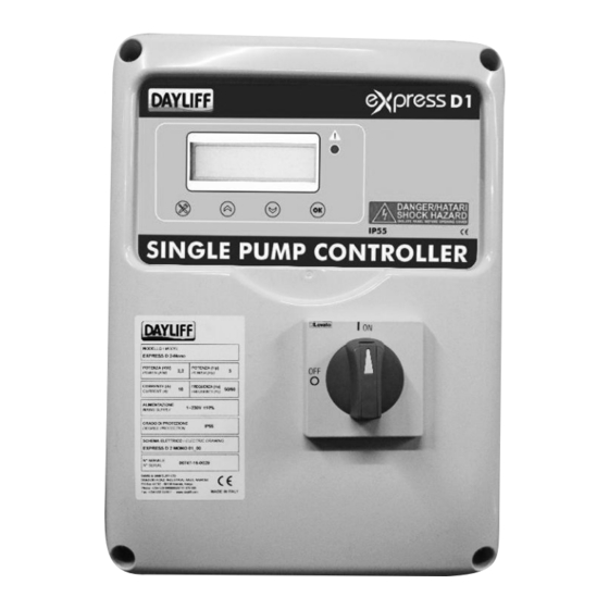
- Page 1 EXPRESS ELECTRONIC PUMP CONTROLLER Installation & Operating Manual...
- Page 3 INDEX CONTROLLER SPECIFICATIONS 2. SYMBOLS & WARNINGS CONTROLS INDICATORS 4.1 Main Display Items 4.2 Activation of Load in Manual Mode 5. FUNCTION AND SETTINGS 5.1 Function 1: Draining with oats / pressure Switches 5.2 Function 2: Draining with level sensors and oats / Pressure Switches 5.3 Function 3: Drainage with “COS FI”...
-
Page 5: Controller Specifications
Single and twin pump EXPRESS controllers for DOL start are available as standard while panels for 3 and 4 pump operation and Star-Delta start can be suppled on request. Dayliff EXPRESS is a fully integrated controller that is adaptable to almost any pump control... -
Page 6: Controller Functions
GENERAL DATA Dimensions (mm) Start Motor Current Controller Model (kg) Method Size Height Width Length EXPRESS D1-1ph 0.37-2.2kW EXPRESS D1-3ph/7.5 0.55-7.5kW EXPRESS D1-3ph/15 0.55-15kW EXPRESS D2-1ph 0.37-2.2kW EXPRESS D2-3ph/7.5 0.55-7.5kW Express D1/D2 - 1ph Express D1 - 3ph Express D2 - 3ph... - Page 7 5 days of receiving the goods, the nearest Davis & Shirtliff retailer. The Dayliff EXPRESS electrical panel must be used exclusively for the purpose and function as specified in design. Any other application or use is to be considered improper and...
- Page 8 • Partial or total failure to observe instructions. 3. CONTROLS The Dayliff EXPRESS electrical panel has been designed for settable protection of 1 to 4 motors with the option of selecting the operating mode according to the specific system used.
-
Page 9: Main Display Items
Display of values and programming. EXPRESS Red led: general alarm SETUP (or multifunction) button UP arrow button DOWN arrow button OK button 4. INDICATORS 4.1 Main display items On activation of the panel, the display shows the following: MODEL EXPRESS E L E N At the end of the start-up sequence, the main menu is displayed, as described below;... -
Page 10: Functions And Settings
ashes. CAUTION 5. FUNCTIONS AND SETTINGS The Dayliff EXPRESS panel features a host of internal functions. There are basically 8 operating modes developed for various types of application as described below. -
Page 11: Programming Menu
Programming Menu To select the panel operating logic, access the programming menu by pressing the buttons SETUP , UP and DOWN at the same time on the main screen of the panel. DESCRIPTION OF PARAMETER VALUE FAULT Language 0 ITA / 1 ENG/ 2 FRA Operating Logic Number of Pumps This parameter enables selection of the number of pumps in the system... - Page 12 DESCRIPTION OF PARAMETER VALUE FAULT Minimum Voltage 207 (230) Set by default at -10% . Modifications to operating limits beyond the default parameters will 360 (400) i m m e d i a t e l y r e n d e r t h e w a r r a n t y n u l l a n d v o i d . Maximum Voltage 253 (230) Set by default at +10% .
- Page 13 Programming Menu To select the panel operating logic, access the programming menu by pressing the buttons SETUP, UP and DOWN at the same time on the main screen of the panel. DESCRIPTION OF PARAMETER VALUE FAULT Language 0 ITA / 1 ENG/ 2 FRA Operating Logic Number of Pumps This parameter enables selection of the number of pumps in the system...
- Page 14 DESCRIPTION OF PARAMETER VALUE FAULT Minimum Voltage 207 (230) Set by default at -10% . Modifications to operating limits beyond the default parameters will 360 (400) i m m e d i a t e l y r e n d e r t h e w a r r a n t y n u l l a n d v o i d . Maximum Voltage 253 (230) Set by default at +10% .
- Page 15 Programming Menu To select the panel operating logic, access the programming menu by pressing the buttons SETUP , UP and DOWN at the same time on the main screen of the panel. DESCRIPTION OF PARAMETER VALUE FAULT Language 0 ITA / 1 ENG/ 2 FRA / 3 ESP Operating Logic Number of Pumps ThThis parameter enables selection of the number of pumps in the system...
- Page 16 DESCRIPTION OF PARAMETER VALUE FAULT Minimum Voltage 207 (230) Set by default at -10% . Modifications to operating limits beyond the default parameters will 360 (400) i m m e d i a t e l y r e n d e r t h e w a r r a n t y n u l l a n d v o i d . Maximum Voltage 253 (230) Set by default at +10% .
- Page 17 Programming Menu To select the panel operating logic, access the programming menu by pressing the buttons SETUP , UP and DOWN at the same time on the main screen of the panel. DESCRIPTION OF PARAMETER VALUE FAULT Language 0 ITA / 1 ENG/ 2 FRA / 3 ESP Operating Logic Number of Pumps This parameter enables selection of the number of pumps in the system...
- Page 18 User Menu On completion of panel operation programming, enter the setup menu to configure the various data for motor start-up. To access the user menu, press the button SETUP for 4 seconds in the main screen of the panel. DESCRIPTION OF PARAMETER VALUE FAULT Minimum Voltage...
- Page 19 Programming Menu To select the panel operating logic, access the programming menu by pressing the buttons SETUP, UP and DOWN at the same time on the main screen of the panel. DESCRIPTION OF PARAMETER VALUE FAULT Language 0 ITA / 1 ENG/ 2 FRA / 3 ESP Operating Logic Number of Pumps This parameter enables selection of the number of pumps in the system...
- Page 20 DESCRIPTION OF PARAMETER VALUE FAULT Full Scale Of Analogue Signal This parameter enables selection of the full scale of the analogue signal As per order 1.0 - 999.9 on input to the panel. User Menu On completion of panel operation programming, enter the setup menu to configure the various data for motor start-up.
- Page 21 5.6 FUNCTION 6 - Pressurisation with analogue signal and COS-PHI power factor control This operating mode is used for pressurisation applications managed via analogue signals with dry running safety control, obtained from the Cos-Phi power factor (where "Phi" is the timing angle between current and voltage), without the need for external commands (float or pressure switch), enabling the control of one or more pumps.
- Page 22 DESCRIPTION OF PARAMETER VALUE FAULT COS-PHI Alarm Output This parameter enables removal of the dry running alarm from the Y or N cumulative alarm output. Type Of Analogue Signal As per order This parameter enables selection of the type of analogue signal on input 0 or 1 to the panel: 0 = 0-10 V...
- Page 23 DESCRIPTION OF PARAMETER VALUE FAULT Sequential Reset On Dry Running Alarm If the value 0 (zero) is set, all automatic resets are blocked after the fourth attempt; if the value is set to 1 (one) at the end of the fourth attempt, the reset cycle is repeated continuously;...
- Page 24 Programming Menu To select the panel operating logic, access the programming menu by pressing the buttons SETUP, UP and DOWN at the same time on the main screen of the panel. DESCRIPTION OF PARAMETER VALUE FAULT Language 0 ITA / 1 ENG/ 2 FRA / 3 ESP Operating Logic Sensor Sensitivity (Sa - Sb - Sc - Sd) This parameter enables display of sensor sensitivity.
- Page 25 Programming Menu To select the panel operating logic, access the programming menu by pressing the buttons SETUP, UP and DOWN at the same time on the main screen of the panel. DESCRIPTION OF PARAMETER VALUE FAULT Language 0 ITA / 1 ENG/ 2 FRA / 3 ESP Operating Logic COS-PHI Alarm Output This parameter enables removal of the dry running alarm from the...
- Page 26 DESCRIPTION OF PARAMETER VALUE FAULT Maximum Current P1 / P2 / P3 / P4 This parameter enables entry of the maximum current for each motor. Enter the maximum current value, increasing it by 10-15% with respect to the 1 - … A As per order rated motor value.
- Page 27 The load current absorption is higher than the set value and the panel A L A R M M O T O R I N P R O T E C T I O N shuts down the relative pump. The display and red led flash and the cumulative alarm output is activated (voltage-free contacts NC-C-NO).
- Page 28 Connection problems between motherboard and expansion modules. A L A R M M O T O R The display and red led flash and the cumulative alarm output is C O M M U N I C AT I O N activated (voltage-free contacts NC-C-NO).
-
Page 29: Terms Of Warranty
7. TERMS OF WARRANTY i) General Liability In lieu of any warranty, condition or liability implied by law, the liability of Davis Ÿ & Shirtliff (hereafter called the Company) in respect of any defect or failure of equipment supplied is limited to making good by replacement or repair (at the Company’s discretion) defects which under proper use appear therein and arise solely from faulty design, materials or workmanship within a specified period. -
Page 30: Maintenance
Maintenance Dayliff EXPRESS does not require routine maintenance provided that it is used within the operating limits and in observance of the instructions in this manual. 6 6 6 26... -
Page 31: Declaration Of Conformity
8. DECLARATION OF CONFORMITY Dayliff Express Pump Controllers comply with the following EU directives. ELENTEK Srl with registered offices in via A. Meucci, 5/11 - 35028 Piove di Sacco (PD) ITALIA, declares under its sole responsibility that the machine: Express Series... - Page 32 www.davisandshirtliff.com INS369A-05/17...