Table of Contents
Advertisement
Advertisement
Table of Contents

Related Manuals for DAYLIFF SUNVERTER B


Summary of Contents for DAYLIFF SUNVERTER B
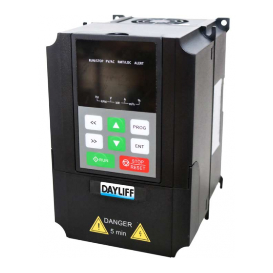
- Page 1 SUNVERTER B AC SOLAR PUMP CONTROLLER Installation & Operating Manual...
- Page 2 INDEX CONTROLLER SPECIFICATIONS 2. SYMBOLS & WARNINGS 2.1 Purchase Inspection 2.2 Installation 2.3 Wiring 2.4 Operation 2.5 Maintenance 2.6 Others 3. INSTALLATION & WIRING 3.1 Installation Instructions 3.2 Installation Method 3.3 Installation Steps 3.4 Wiring Instructions 3.5 Wiring Diagrams of Various Power Supply Arrangements 3.5.1 Wiring Diagram for Solar Supply for Single Phase Pump...
- Page 3 5. TROUBLE SHOOTING 5.1 Common Faults and Solutions 5.1.1 No Display after Power On 5.1.2 Tripping After Power or During Operation 5.1.3 The Pump Does Not Work 5.1.4 The Inverter Displays Fault Code 6. MAINTENANCE 6.1 Routine Inspection & Maintenance 6.2 Inspection &...
-
Page 4: Controller Specifications
Grid Pump Dayliff SunVerter B is an AC/DC inverter specially designed for solar powering AC motors in various water pumping applications and is suitable for retro fitting to existing AC supply installations. It is enclosed in a plastic casing with IP20 protection grade suitable for indoor installations or can be supplied with an additional enclosure for outdoor applications. -
Page 5: Installation
Ÿ Fault detection with error code display. INSTALLATION Dayliff SunVerter B controllers are surface mounted and should be provided with an enclosure for water and heat protection. Due to the high operating voltages proper earthing is essential, which must be carried out by a qualified electrician. -
Page 6: Symbols And Warnings
2. SYMBOLS AND WARNINGS Misuse will result in re, serious injury to persons or even death. WARNING Incorrect use may cause mild or moderate body injuries and damage to devices. CAUTION 2.1 Purchase Inspection Do not install the inverter if there is water or water stains inside. - Page 7 Assemble and tighten the xing screws of the inverter according to the regulations, otherwise the inverter may accidently fall off and get damaged. DANGER It is not allowed to install the inverter in environment containing explosive gas, otherwise it may cause explosion. DANGER It is not allowed to install the inverter in place accessible to children and other public, otherwise it may cause electric...
- Page 8 The inverter must be grounded reliably, otherwise it may cause electric shock. DANGER The terminal signal cable of the inverter should be put away from the power cable as far as possible. If the distance is not enough, they should be cross-distributed vertically, WARNING otherwise it will cause signal interference.
- Page 9 Do not touch the fan or radiator base, otherwise it may cause mechanical injuries or burns. DANGER Do not frequently turn on and turn off the inverter input power, otherwise it may damage the inverter. WARNING The inverter must be in no output state when the circuit breaker or contactor at the output of the inverter is switched on or off, otherwise it may damage the inverter.
-
Page 10: Installation And Wiring
2.6 Others At the end of its design life, the inverter should be disposed as industrial waste. During incineration, the electrolytic capacitor may explode and some parts may produce toxic WARNING and harmful gases. 3. INSTALLATION AND WIRING 3.1 Installation Instructions Installation of the inverter according to the installation environment requirements is the precondition for ensuring long-term normal and stable operation of the inverter. - Page 11 Fig 1: Installation Direction and Space Requirements Installation Space Dimensions (mm) Inverter Rated Power ≥ 37kW ≥50 ≥200 ≥80 ≥300 >37kW If multiple inverters are to be installed in the same cabinet, it is recommended to Ÿ adopt transverse side-by-side installation. If two inverters are to be installed longitudinally, a guide plate should be added in the middle.
- Page 12 Models 2.2kW Models 4-11kW Models>11kW Fig 2: Sunverter B Open Cover Diagram 3.5 Wiring Diagrams of Various Power Supply Arrangements 3.5.1 Wiring Diagrams for Solar Supply for Single Phase Pump...
- Page 13 3.5.2 Wiring diagram for Solar Supply for Three Phase Pump 3.5.3 Concurrent connection of AC Mains Supply and Solar Supply with Diode Module Without the DIODE module, only one power supply can be connected at a time i.e. AC mains or PV solar. NOTE 4 10...
- Page 14 Name Function Terminal Mark PV+/PV- PV Input PV array input terminals 3PH/380V-415V AC power input R/S/T terminals. Any two terminals for AC Input for SVB/T three 1PH/220V-240VAC power input for p h a s e m o d e l s a n d SVB/4M single phase model.
- Page 15 The basic wiring of Sunverter B is shown in Fig.3 Ÿ Disconnect Note: For Single Phase m o d e l s & terminals of inverter should be connected Sunverter B Solar Pumping to L&N terminals of Inverter single phase pump with capacitors or via capacitor control box.
- Page 16 Terminal Type Function Description Technical Specications Label Input specification: 24 V, 5 mA DI1: Operation control signal, valid when connected to COM (connected by default) DI2: Tank full signal, valid when connected to COM (disconnected by default) DI3: Source low signal, valid w h e n c o n n e c t e d t o C O M (connected by default) DI1~DI5...
- Page 17 Terminal Type Function Description Technical Specications Label T1A-T1B: normally close (AC contactor coil control contacts in T1A/T1B/T AC/DC power switching function) Relay output 1 T1A-T1C: normally open Contact R e l a y capacity: AC 250 V/3 A, DC 30 Output V/1 A T e r m i n a l...
-
Page 18: Cable Sizing
SVB/75T-SVB/110T Main Circuit Terminal Function Description Terminal Screen Function Description Printing Name Three-phase (single-phase) power supply input terminal. For R, S, T SVB/4M, any two terminals (R,S,T) can be used to connect single (L, N) phase supply Positive and negative terminal of the solar array (+), (-) Three-phase AC output terminal, connected to pump motor U, V, W... -
Page 19: Other Notes
Other Notes A DC circuit breaker must be installed as protection switch for solar DC input. Ÿ The inverter only has one pair of DC input terminals. If the solar modules are Ÿ multi-paralleled, an additional solar combiner box is necessary. The inverter must be grounded reliably and the grounding cable should be as Ÿ... - Page 20 Panel Name Description Label Frequency Indicator Light Unit of current display parameter is Hz Voltage Indicator Light Unit of current display parameter is V Current Indicator Light Unit of current display parameter is A Percentage Indicator Light Unit of current display parameter is percentage Rotation Speed Indicator Light Unit of current display parameter is RPM Power Indicator Light...
- Page 21 Operation Panel Key Function Name Function Description Appearance Programming Key Enter or exit the first-level menu; Return to previous menu. In variable display mode, left shift to circularly display different variables such as frequency, speed, voltage, current, etc. In Shift Key (Left) parameter setting mode, left shift to select the bit to be modified;...
- Page 22 SVB will display “8.8.8.8.8” during power-on initialization and then display the setting frequency. To modify a parameter, please press to enter the rst level menu, NOTE which displays F00. Then, press t o s e l e c t t h e group number of the parameter and enter the second level menu by pressing .
-
Page 23: Initial Settings Before First Operation
Stop Display State The inverter operation panel will display eight stop state parameters in stop state by default, which are the same parameters as in operation state. Press sequentially left/right shift to display operation state parameters. In stop state, RUN/STOP indicator light is off, RMT/LOC indicator light blinks and the corresponding unit indicator lights of current display state parameter will turn on. -
Page 24: Function Parameters
Step Initial Setting Content Operating Method If no water comes out when the pump is operating at 15 Hz (the default value of function parameter F15.19), Set low sunlight frequency please increase the set value of F15.19 until water comes out to avoid ineffective operation when light is weak 4.4 Function Parameters The parameters of SVB Solar Pumping Inverter are grouped by function. - Page 25 Setting Default Modi- Function Description Name Range Value ability Code Setting the maximum output frequency of the Maximum inverter It is the basis of VF curve setting and F00.04~ Output F00.03 50.00Hz rate of acceleration/deceleration. 600.00 Frequency Unit: Hz 0: No action 1:Restore factory settings Restore all function parameters to default values except F02 Restore...
- Page 26 Setting Default Modi- Function Description Name Range Value ability Code F04: V/F Control Group 0: Straight line 1: Multi-dots V/F curve, manually set V/F curve through F04.03~F04.08 2: 1.3th power torque reduction V/F curve V/F Curve 3: 1.7th power torque reduction V/F curve F040.00 Type 4: 2.0nd power torque reduction V/F curve...
- Page 27 Setting Default Modi- Function Description Name Range Value ability Code F05: Input Terminal Group Terminal DI1 0: No function F05.01 Function 1: Forward rotation operation 2~41: Reserved Terminal DI2 42: Disable solar inverter, force the inverter 0~63 F05.02 Function to operate at power frequency (can be used in AC/DC automatic s w i t c h i n g Terminal DI3 F05.03...
- Page 28 Setting Default Modi- Function Description Name Range Value ability Code 0: Only valid in panel run/stop control mode 1: Valid in panel and terminal run/stop STOP/RESET control modes Key Stop F07.04 2: Valid in panel and communication Function run/stop control modes Valid Mode 3: Valid in all run/stop control modes BIT0: Operating frequency (light Hz on)
- Page 29 Setting Default Modi- Function Description Name Range Value ability Code Inverter Power 0.0~ Unit: kWh F07.16 Consumption 999.9 (low byte) Determin Inverter Rated 0.4~ Unit: kW ed by F07.18 Power 3000.0 model Determin Inverter Rated Unit: V F07.19 50~1200 ed by Voltage model Determin...
- Page 30 Setting Default Modi- Function Description Name Range Value ability Code F08: Auxiliary Parameters Group If the same fault occurs repeatedly and Fault reaches this number of times, it will not be F08.28 0~10 Automatic reset again and manual intervention is Reset Times required.
- Page 31 Setting Default Modi- Function Description Name Range Value ability Code The percentage of F00.03 maximum output PID Control frequency value. Maximum F15.05~ F15.04 100.0% The target frequency obtained from PI Output 100.0 control cannot be higher than this set value. Frequency PID Control The percentage of F00.03 maximum output...
- Page 32 Setting Default Modi- Function Description Name Range Value ability Code Solar Voltage 0: DC bus voltage Measurement F15.16 1: AIN, input terminal of Boost module Target Tank Full Tank full duration time before tank full alert. 0.0~ F15.17 10.0s Alert Delay Unit: second 3600.0 Time...
-
Page 33: Troubleshooting
Times 5. TROUBLE SHOOTING Sunverter B Solar Pumping Inverters have complete protections. When a fault occurs, the inverter will take protection actions: the general protection is to instantly stop the output of the motor driving signal (shut down) and prohibit restarting for a period of time. - Page 34 Check whether there is no voltage output. If so, the driving board or output • module may be damaged. Please contact Dayliff for help. 5.1.4 The inverter displays fault code and cannot operate If a fault occurs during the use, please check the fault code in parameters •...
- Page 35 1. Acceleration is too fast 1. Increase acceleration time OUt1 Fault 2. The IGBT of corresponding 2. Contact Dayliff for help phase is damaged internally 3. Check whether there are strong IGBT Phase V 3. Misoperation caused by interference sources in the peripheral...
-
Page 36: Routine Inspection And Maintenance
Fault Possible Causes Solutions Fault Type Code Operating Time C o n t a c t t h e m a n u f a c t u r e r h e l p User trial time is over Over 1. - Page 37 6.2 Inspection and Maintenance Requirements 1. The inspection must be performed by professional technicians and the power supply of the inverter should be cut off first if necessary. 2. Before maintenance, the power supply of the inverter must be cut off, and please wait for not less than the time indicated on the inverter or the DC bus voltage is lower than 36 V.
- Page 38 6.5 Storage The storage environment should meet the following requirements: Item Storage Environment Temperature -40 C~70 C Humidity 5% ~95%, no dew condensation Ambient No direct sunlight, no dust, no corrosive gas, no vibration (can use a plastic bag Enviromnent to seal and add desiccant inside) Long-term storage will cause deterioration of the electrolytic capacitor.
-
Page 39: Terms Of Warranty
General Liability • In lieu of any warranty, condition or liability implied by law, the liability of Dayliff (hereafter called the Distributor) in respect of any defect or failure of equipment supplied is limited to making good by replacement or repair (at the Distributor’s discretion) defects which under proper use... - Page 40 www.davisandshirtliff.com INSXXA-11/21...
Need help?
Do you have a question about the SUNVERTER B and is the answer not in the manual?
Questions and answers
Dayliff sunverter is show AL low despite adequate sunshine. What could be the problem.
The Dayliff Sunverter B could show AL low (source low alert or load low alert) despite adequate sunshine due to the following reasons:
1. Improper wiring or connection issues affecting power delivery from the PV array.
2. Undersized or incorrectly configured PV solar module array not providing sufficient voltage or current.
3. Faulty components such as a damaged PV module, inverter, or controller.
4. Overheating or internal faults triggering protection modes, reducing power output.
5. The DC bus voltage dropping below the configured instant power loss frequency reduction point, causing system derating.
All connections and system configuration should be checked and verified by a qualified technician.
This answer is automatically generated