Advertisement
Table of Contents
- 1 Troubleshooting
- 2 Controller Specifications
- 3 Installation
- 4 Operating Conditions
- 5 Symbols and Warnings
- 6 Installation and Wiring
- 7 Electrical Connection
- 8 Hybrid Installation
- 9 Operation and Control
- 10 Panel Operation
- 11 View Historical Data
- 12 Function Parameter Description
- 13 Other Codes Description
- 14 Service and Maintenance
- 15 Terms of Warranty
- 16 Standard Warranty
- Download this manual
Advertisement
Table of Contents

Related Manuals for DAYLIFF SUNVERTER 4


Summary of Contents for DAYLIFF SUNVERTER 4
- Page 1 SUNVERTER 4 AC SOLAR PUMP CONTROLLER Installation & Operating Manual...
- Page 3 INDEX CONTROLLER SPECIFICATIONS 2. SYMBOLS & WARNINGS 2.1 Purchase Inspection 2.2 Installation 2.3 Wiring 2.4 Connection 2.5 Running 2.6 Hybrid Operation 2.7 Others 3. INSTALLATION & WIRING 3.1 Installation Environment Requirements 3.2 Installation Direction 3.3 Installation Method 3.4 Wiring Diagram 3.5 Electrical Connection 3.6 Single Phase Motor Wiring Installation 3.7 Water Level Switch Installation &...
-
Page 4: Troubleshooting
5. TROUBLE SHOOTING 5.1 Fault Code Description & Solutions 5.2 Fault Abnormal Code Description 5.3 Faulty Inquiry & Reset 5.4 Other Codes Description SERVICE & MAINTENANCE 6.1 Routine Inspection & Maintenance 6.2 Requirement of Inspection & Maintenance 6.3 Main Points for Inspection & Maintenance 6.4 Inspection &... -
Page 5: Controller Specifications
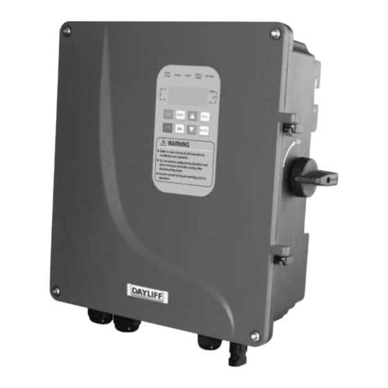
Control Pump The Dayliff Sunverter 4 is the latest update of the established Sunverter range of advanced AC/DC inverters specially designed for solar-powering AC motors in various water pumping applications. As well as a general upgrade of the electronics and functionality an important new feature is hybrid capability that enables concurrent operation with direct AC power from mains or generator supply while prioritising solar supply. -
Page 6: Installation
INSTALLATION Dayliff Sunverter 4 controllers are surface mounted and should be provided with a housing for water and heat protection. Due to the high operating voltages proper earthing is essential, which must be done by a qualified electrician. As a rule, all PV powered solar pumping systems should be provided with a solar module array with a nominal output about 30% greater than the motor size. -
Page 7: Symbols And Warnings
2. SYMBOLS AND WARNINGS Misuse of this Inverter will result in re, serious injury, or even death. It can also cause low or middle-level injury to persons or equipment damage. 2.1 Purchase Inspection Check the inverter before installation. Do not install if it is damaged or with missing parts, else may cause accidents. - Page 8 2.4 Connection To avoid the risk of re, make sure to securely tighten the terminal using the specied torque. CAUTION Do not connect capacitor or phase-advanced LC/RC noise lter with inverter output. CAUTION Make sure all the wiring and connection are correctly connected before powering on, or else may damage the PV disconnect switch or cause re.
-
Page 9: Installation And Wiring
At the end of its design life, the inverter should be disposed as industrial waste. During incineration, the electrolytic capacitor may explode and some parts may produce toxic WARNING and harmful gas. 3. INSTALLATION AND WIRING 3.1 Installation Environment Requirements Installation of the inverter according to the specified environmental conditions is the precondition for ensuring long-term normal and stable operation of the inverter. - Page 10 3.2 Installation Direction Leave enough installation space between inverter and other objects nearby to Ÿ ensure good ventilation and heat dissipation. As shown on Fig 1, install the inverter vertically or backwards with maximum 10 inclination angle Do NOT install horizontally or transversely. Install the inverter at a height that is convenient to operate and read in the LCD Ÿ...
- Page 11 Fig 2: Mounting Hole Fig 3: Inverter Mounting Diagram Installation Diagram The installation surface should be at and closely attached to the inverter bottom surface to ensure good heat dissipation. If the installation surface is not at, a wind deector can be NOTE installed on the back of the inverter in advance to enhance the heat dissipation capacity.
- Page 12 3.4 Wiring Diagram Fig 4: System Wiring Diagram...
- Page 13 Terminal Description Connection Description Socket Connected to positive pole of solar array DC Input Connected to negative pole of solar array Connected to R phase of grid Connected to S phase of grid Three - Phase AC Input Connected to T phase of grid Connected to earth cable Connected to L phase of grid Single - Phase...
- Page 14 For single-phase pumps, remove the external capacitor before wiring NOTE Function Description Terminal Terminal Name Tank water level signal input, open circuit is normal, Water level sensor signal short circuit is abnormal. Function setting through TANK-COM input terminal for tank Pr15, default value 7 Well water level signal input, open circuit is Water level sensor signal...
- Page 15 In order to ensure communication quality, use twisted shielded pair cable as communication cable. NOTE All analog, digital, power and signal cables should be separated to avoid entanglement. NOTE Solar Array AC Cable (mm ) Earth Cable (mm ) Signal Cable Model Cable (mm ) (mm )
-
Page 16: Electrical Connection
3.5 Electrical Connection Step 1 : Prepare all the input/output cables as shown in Fig 5. Single Core Cable Stripping Multi-Core Cable Stripping Diagram Diagram Crimping Diagram Fig 5: Cable Preparation Diagram. Type Process Description Cable Single-Core Strip 10mm at A Power Cable Strip 50mm at A and 10mm at B Multi-Core... - Page 17 Fig 6: Wiring Diagram Step 3: After finishing the wiring, tighten the bottom waterproof PG terminal with a tightening torque of 7Nm and lock the upper cover. Fix the earth cable to the ground screw at the bottom of the housing. Fig 7: Shell Grounding Operation Diagram Step 4: Turn the knob of the DC disconnect switch on the right side of the inverter to “ON”...
- Page 18 3.6 Single Phase Motor Wiring Instruction To wire single phase motors to the Sunverter 4, if the motor has an external capacitor box, wire as per Fig 9a. where you connect the SV4 terminals A and M to the capacitor box.
- Page 19 Calculation Ÿ Add all A’s = 12Ω -> Lowest Reading = 'Common" winding - C Ÿ Add all B’s = 19Ω -> Highest Reading = 'Start/Auxiliary" winding - A Ÿ Add all C’s = 17Ω -> Second Highest Reading = 'Run/Main" winding – M Connect the motor to the Inverter A, M, C port.
-
Page 20: Hybrid Installation
These components effectively reduce noise and prevent interference with other components or systems. Consult nearest Dayliff dealer for the extra accessories such as AC disconnect/ AC Ÿ breaker combiner, surge suppressor and reactors. - Page 21 Three Phase Inverter AC Power Input Bridge PV Array Input Fig 12 Hybrid Power Supply Main Circuit Recommended PV array voltage conguration: As illustrated below, when the maximum power point voltage (Vmp) of the PV array matches the bus voltage (Vdc) while the system is operational, the PV array can produce its maximum power (Pmax).
-
Page 22: Operation And Control
Motor Max DC Output Rated Rated Voltage Input Voltage Current Model Power VDC, Voltage Voltage VDC, (kW) Hybrid Solar SV4/1.5M 125-360 125-370 SV4/2.2M 1x240V 180-360 180-370 SV4/3.0M 250-360 250-370 4. OPERATION AND CONTROL 4.1 Initial Settings before First Operation While implementing initial settings below, refer to section 4.6 on how to view and modify parameters as well as section 4.7 for detailed parameter descriptions Step Initial Setting Content... - Page 23 Step Initial Setting Content Operating Method 1. Press RUN key 2. Observe if there's water flowing out of the outlet 3. If there is no water flowing out, press UP key slowly to increase output frequency 4. When water starts flowing from the outlet, record the Modify the minimum operation start operation frequency f0.
- Page 24 Identication Name Color Function Description Frequency Indicator Light Unit of current display parameter is Hz Voltage Indicator Light Unit of current display parameter is V Current Indicator Light Unit of current display parameter is A Rotation Indicator Light Unit of current display parameter is RPM Light Power Indicator Light Unit of current display parameter is W...
-
Page 25: Panel Operation
Indicator Lights & Name Function Keys Switch the display data type of PV input/AC input Right Shift Key >> Output/ Others when viewing running data Shift right to switch the bit to be edited. Enter or quit from the display status of the control Programming Key PROG parameter... -
Page 26: View Historical Data
4.5 View Historical Data 4.6 View or Modify Control Parameter Description Operation Display E n t e r t h e p a r a m e t e r PROG modification interface: Display parameter 0 Select the parameter to be viewed and modified: >>... -
Page 27: Function Parameter Description
When the inverter is operating, the control parameter can only be viewed. To modify them, the inverter must rst be stopped. NOTE 4.7 Function Parameter Description Factory Scope Description Name Number Value 0: Parameter can be read and edited. Other parameter values cannot be modified until this parameter is modified to 0. - Page 28 Factory Scope Description Number Name Value Minute required to be corrected. Pr.10 Minute 0-59 The upper limit of output frequency of current Frequency Upper Pr.11 0-Pr.13 50Hz operation. Limit The maximum AC input power ration when Input AC power Pr.12 10-100 CRUISE is enabled.
- Page 29 Factory Scope Description Number Name Value Record the last 4 fault codes. It will only display the Fault Type Record Read Only Pr.20-23 first six characters of the fault code here for d e s c r i p t i o n s s e e c h a p t e r 4 . Start delay time in seconds after power on or Start delay time 1-6,000...
- Page 30 4.8 Common Function Description a) Pump Speed Adjustment During the operation of the pump, press key to modify the upper limit frequency to set the pump speed, please note that the actual maximum speed of the pump is also limited by the PV input power and voltage and may not reach the set speed. After 5 minutes of continuous operation, this setting value will be record and set in Pr.11.
- Page 31 Too large load Overload Output short circuit or Inspect the wiring Over current of grounded Refer to the nearest Dayliff dealer for internal module Module damage assistance Wait for fault recovery (please consult Too high input in rush current with manufacturer in advance when...
- Page 32 Inverter selection does not inverter capacity match the pump All parameters initialization Memory chip read/write error Parameter error Refer to the nearest Dayliff dealer for Device or circuit damaged assistance Output cable damaged Inspect cable connections Output short circuit Pump motor insulation...
-
Page 33: Other Codes Description
5.3 Fault Inquiry and Reset The Sunverter records the fault codes of the latest 4 events. Searching this information will help find the fault cause. Fault information is stored in the control parameters Pr.20~Pr.23 refer to the panel operation instructions to view the fault codes and find solutions. - Page 34 PROBLEM POSSIBLE CAUSE SOLUTION Indicator light is off Check DC input wires connection Inverter does not work when powered Cut of inverter input wires and check if Indicator light is on input voltage is abnormal Reset the motor starter overload. If it trips again, check the voltage else call service The motor overload has tripped out technician...
- Page 35 PROBLEM POSSIBLE CAUSE SOLUTION The water level sensor not installed Check water level sensor and correct correctly Frequent starts Pull out the pump and clean or replace The non-return valve is leaking or stuck the non-return valve and stops half open Increase the installation depth of the pump, throttle the pump or replace it The pump is oversized for borehole...
-
Page 36: Service And Maintenance
6. SERVICE AND MAINTENANCE 6.1 Routine Inspection and Maintenance Sunverter 4 is affected by ambient temperature, humidity, dust, vibration and internal device aging. To ensure long term operation a yearly inspection is recommended. 6.2 Requirement of Inspection and Maintenance The inspection must be performed by a qualified technician. - Page 37 6.4 Inspection and Replacement of the Replaceable Component Filter Capacitor The performance of the aluminum electrolytic filter capacitor in the main circuit may be impacted by the pulsating current, ambient temperature, and application conditions. It is advisable to replace the inverter's electrolytic capacitor after 10 years of use. However, immediate replacement is necessary if there are indications of electrolyte leakage or expansion of the safety valve on the capacitor.
-
Page 38: Terms Of Warranty
General Liability • In lieu of any warranty, condition or liability implied by law, the liability of Dayliff (hereafter called the Distributor) in respect of any defect or failure of equipment supplied is limited to making good by replacement or repair (at the Distributor’s discretion) defects which under proper use... - Page 40 www.davisandshirtliff.com INS475B-04/22...
Need help?
Do you have a question about the SUNVERTER 4 and is the answer not in the manual?
Questions and answers