Advertisement
Quick Links
Advertisement

Subscribe to Our Youtube Channel
Related Manuals for DAYLIFF PVm015


Summary of Contents for DAYLIFF PVm015
- Page 1 PUMPVERTER VFD CONTROLLER Installation & Operating Manual...
- Page 2 INDEX CONTROLLER SPECIFICATIONS 2. SYMBOLS & WARNINGS 3. WIRING 3.1 Main Circuit Terminals Wiring 3.2 Main Circuit Wiring 3.3 Controls Terminals Connection 3.4 Wiring Main Circuit Installation Accessories 4. OPERATION 4.1 Keypad Description 4.2 Operational Procedure 5. INVERTER PARAMETER DESCRIPTION 6.
-
Page 3: Controller Specifications
1. CONTROLLER SPECIFICATIONS DAYLIFF Pumpverter drives are high specification VSD's suitable for use in residential and industrial applications. They are compact and versatile and can be installed in either motor or wall mounted configuration. The inverter varies pump motor speed with demand thus regulating pump output to a preset outlet pressure. -
Page 4: Symbols And Warnings
Dimensions (mm) Weight Model Motor Supply Output Current (A) (Kg) (kW) Voltage Voltage (V) PVm015 1x240 1x240 PVm022 3x240 PVm075 3x415 3x415 PVm150 2. SYMBOLS AND WARNINGS Do not dismantle the product as it may cause electric shock, re hazard or personal injury. - Page 5 CAUTION If the controller appears to have vibration, noise, heat or peculiar smell during initial operation, cut off power immediately and contact authorised Dayliff retailer. CAUTION Do not install the controller under direct sunlight or rain. CAUTION...
- Page 6 Mains circuit wiring for PVm40, PVm75 POWER MOTOR Mains circuit wiring for PVm 11-15kW POWER MOTOR Terminal Symbol Function Description Terminals of single phase AC input Motor wiring terminal. Note: V, W for PVm15 U, V, W Terminals for ground Terminals of 3 phase AC input R, S, T (+), (-)
- Page 7 3.3 Control Terminals Connection Figure 2: Wiring Diagram 3.4 Wiring Main Circuit Installation Accessories Figure 3: High performance main circuit wiring...
-
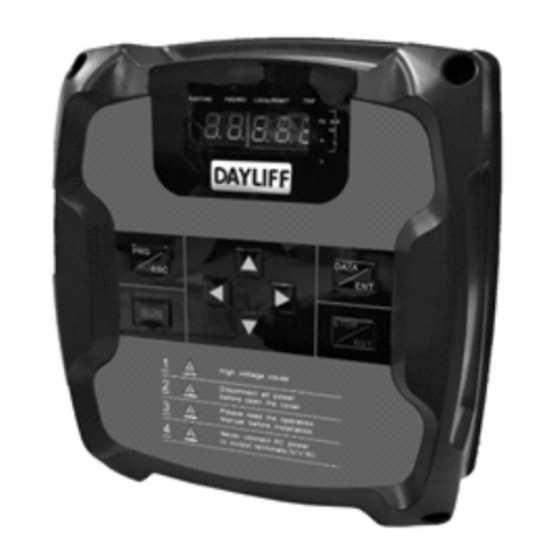
Page 8: Operation
Circuit Breaker It is necessary to connect a suitable circuit breaker between AC power supply and the Pumpverter. The capacity of breaker should be 1.5~2 times the rated current of controller. AC Reactor (Optional) In order to prevent the rectifier damage resulted from the large current, AC reactor should be installed at the input side. - Page 9 H: Operating Frequency P: The Actual Pressure of Pump Outlet L: The Set Pressure of Pump Outlet A: Output current D: DC Bus Voltage U: Output Voltage 4.2 Operation Procedure Power-on Initialization When power is switched on the system initializes and LED displays controller model. After the initialization is completed, the controller switches to stand-by mode.
-
Page 10: Operation Flow Chart
Operation flow chart: Figure 5: Operation Flow Chart Method 2: Direct setting at the primary interface 1. Press or at primary interface, the system will switch-over to display set pressure 2. Press or again, to increase or decrease set pressure. 3. - Page 11 5. INVERTER PARAMETERS DESCRIPTION Function Factory Name Setting Range Description Code Setting Debugging Set at b06.09, default is 65535 0~65535 65535 b00.00 Password S e t a c c o r d i n g t o t h e a c t u a l Pressure Setting 0.0~100bar 3.0bar b00.01...
- Page 12 Function Factory Name Setting Range Description Code Setting 0.00~ All Lower 1.00V • Lower limit use to transducer zero b01.06 10.00V Limit setting • Higher limit use to accordant Corresponding display and transducer pressure Setting of AI1 -100~100% 0.0% b01.07 •...
- Page 13 Function Factory Name Setting Range Description Code Setting PID Output 0:Water Supply 1:Pumping b02.02 Characteristics Determining the strength of PID Proportional regulation, KP is bigger, regulation is 0.00~100.00 2.50 b02.03 Gain (KP) stronger but fluctuates easily Bias between the feedback and the given, determining the speed of Integral 0.00~10.00...
- Page 14 Function Factory Name Setting Range Description Code Setting Al1 Feedback Transducer fault detecting setting Lost Detecting 0.0~100.0% 1.0% b02.08 value, corresponding to full range Value (100%), when the detecting time AI2 Feedback exceeds feedback lost time, it is Lost Detecting 0.0~100% 0.0% b02.09...
- Page 15 Function Factory Name Setting Range Description Code Setting b03.08 Slave Quantity 0: None Fault Master Shift • Invalid: Factory Setting: 2 • Valid: Master set as 0; Slave1 set as 1 Fault Shift/ b03.09 Re m a r k s : Fa u l t s h i f t r e q u i r e s Standby Master connection of backup transducer to Slave 1.
- Page 16 Function Factory Name Setting Range Description Code Setting Setting time from zero to max Acceleration 0.1~3600s Model b05.03 Time Frequency The setting time from max. frequency Deceleration Model 0.1~3600s b05.04 to zero Time Maximum Output Determine the Acc./Dec. rate 10-600Hz 50Hz b05.05 Frequency...
- Page 17 Function Factory Name Setting Range Description Code Setting bit0: Operational frequency bit1: The actual pressure of pump outlet bit2: The setting pressure of pump outlet Running Status bit3: Output current Display 0~0x1FF 0x01F b06.00 bit4: DC bus voltage Selection bit5: Output voltage bit6: Present time bit7: The actual pressure of pump inlet...
- Page 18 Function Factory Name Setting Range Description Code Setting Third Latest b06.04 Fault Type E000~E022 Read Second Latest b06.05 Refer to chapter 9 Only Fault Type Latest Fault b06.06 Type 0: Power off storage Parameters 1: Power off default storage Storage b06.07 2: Invalid Condition...
- Page 19 Function Factory Name Setting Range Description Code Setting Limit of • When regardless of the inlet Day part A water pressure, just set the lower limit as 0. Day part B 00:00~24:00 00-00 b07.05 Starting Time Day part B 0~20.0bar 3.0Bar b07.06 Pressure Setting Day part B...
-
Page 20: Application Guidance
Function Factory Name Setting Range Description Code Setting Motor Rated 0~36000 b08.03 Speed Motor Rated Model 0~460V b08.04 Voltage Motor Rated 0.0~2000A b08.05 Current Reserved 0~65535 00000 b08.06 Set the 65535 Modify password of b07.15 0~65535 b08.07 Password of b07.15 Password of Don't try to enter or will cause xxxxx... - Page 21 6.2 Single Pump Constant Pressure Control Pumpverter 1. Pumpverter Intelligent Controller 2. Pump 3. Pressure tank 4. Non return valve 5. Pressure transducer 6. Water level switch (installed at water source) 7. Fault indicator 8. Power supply indicator 9. Fuse 10.
- Page 22 6.3 Multi-pump Constant Pressure Control Typical System Wiring Diagram: (1)Pumpverter Controller (2)Main Breaker (3)Breaker (4)Power Light (5)Fault Light (6)Motor and Pump (7)Water Level Switch (8)Outlet Transducer on master pump controller (9)Backup Transducer on slave pump controller, that is set as standby master Pumpverter To Use Figure 8 Multi-pump control wiring...
- Page 23 6.4 Parameter Settings for Single and Multi-Pump constrant Pressure Control Single pump constant pressure control Ÿ Set all parameters in table below on controller except b03.00-b03.09, b05.10 Multi-pump constant pressure control: One master Pump, all other pumps slaves Ÿ Master controller should have pressure transducer connected Ÿ...
- Page 24 Setting Factory Recommend Code Name Description Range Setting -ed Setting Maximu For example, if the rated range of transducer is 0-10 bar, b01.05 Transduc should be set to 10.0 0-100 b01.05 10 bar 10 bar setting range AI1 lower Lower limit settings should not be 0-10V 1.0V 1.0V...
- Page 25 Setting Factory Recommend Code Name Description Range Setting -ed Setting 00: Master Controller Commun 01-05: Auxiliary controller (slaves) ication 06-31: Reserved 0-31 00-0N b03.00 Address Auxiliaries should be set as 01-on 0N on order assuming N auxiliary controllers 0: None Slave Slave number, assume 1 master N b03.08...
- Page 26 Setting Factory Recommend Code Name Description Range Setting -ed Setting Low level Delay time in minutes for restart after restart 0-300min 1min 1min b05.01 water level switch recover delay 0: Invalid 1: Electric contact control S1&COM-ON: Frequency rise S2&COM-ON: Frequency drop 2:Manual/Auto control Terminal S2&COM-OFF: Auto control...
- Page 27 Setting Factory Recommend Code Name Description Range Setting -ed Setting When set to 0:0, there will be no Alternatin 8.00h 0-300h 8.00h b05.10 pump alternation. g time Used in multi-pump systems to balance and prolong pump service life. Master and auxiliary pump(s) changeover according to this setting.
- Page 28 6.5 Day-Part Water Supply Application Setting System Wiring Pumpverter In diagram: (1) Pumpverter (2) Pumps (3) Air Pressure Tank (4) Water Inlet Transducer (5) Water Outlet Transducer (6) Water Level Switch (Use in no negative pressure water supply) Figure 8 Day-part water supply wiring Typical Application Use in pipe pressure boosting for positive suction water supply with different pressurisation requirements at different times of the day.
- Page 29 Relevant Parameter Setting Follow section 6.4 to set other parameters first and then refer to this application to set day part control parameters. Factory Code Recommended Description Setting Inlet transducer calibration (b01.11,b01.13), if need b01.11 not detect inlet pressure, do not install inlet transducer but the inlet pressure lower limit of every day-part must b01.13 be set as 0 is needed.
- Page 30 6.6 Terminal Start/ Stop Control Wiring and Setting System Wiring Base on above applications, connect a switch to S1-COM refers to section 4.3 In diagram: (1) Pumpverter Intelligent Controller (2) Pumps (3) Air Pressure Tank (4) Water Outlet Transducer (5) Water Inlet Transducer (6) Water Level Switch (7) External Start/Stop Switch Figure 9 Terminal Start/Stop Wiring...
- Page 31 Pumpverter Pumpverter Pumpverter Figure 10 Manual/Auto control wiring Operation Use in building site for manual control water supply where empty pipes require quick fill up which is achieved by running pumps at full speed. After parameters set, when S2- COM switch is turned on, pump runs at maximum set frequency (full speed). Relevant Parameter Setting According to the application use section 6.4 to set other parameters first and then set auxiliaries b05.02=2.
- Page 32 Relevant Parameter Setting This example uses the pressure switch for control instead of the transducer (Wiring refer to figure 1). Adjustment of the pressure switch cut-in and cut-out pressures should be done before running. For example for 3bar water supply, then up contact adjust above 3bar (such as at 3bar), bottom electric contact below 3bar (such as at 2.8bar).
- Page 33 6.9 Pumping Application System Wiring Pumpverter In diagram; (1) Pumpverter (2) Pumps (3) Water Level Transmitter. Transmitter used is 4-20mA current type. Jumper for AI1 (J19) set to current feedback signal selection I, refer to figure 1 Figure 12 Pumping control wiring Used in environmentally friendly sewage treatment, water level control, drainage and irrigation etc.
-
Page 34: Fault And Trouble Shooting
Factory Code Recommended Description Setting PID output Characteristics, set as pumping b02.02 characteristics Set as the range of water level transmitter b01.05 10.0 100.0 High water pressure/level alarm value, set as the b01.00 8.0 100.0 alarm water level Low water pressure/level alarm value, water level b01.01 0.5 10.0 below this value stop pumping... - Page 35 7. FAULT AND TROUBLE SHOOTING Reason Fault Solution 1. Detector error • Adopt standard detector Display 2. Wrong parameter • Calibration parameter b01.05, Pressure 3. Transducer wires too long b01.08 Error • Shorten wire 1. Loss of pressure • Check transducer Full 2.
- Page 36 Fault 3. Malfunction caused by E002 eliminate interference (OUT2) interference • Check earth wiring 4. Grounding not properly • Contact Dayliff retailer IGBT Ph-W done E003 Fault (OUT3) Over 1. Acc time is too short • Prolong Acc time current 2.
- Page 37 Fault Fault Reason Solution Code Type Over current • Check the power supply 1. High input voltage When • Avoid restarting the motor until it stops 2. Regenerative energy E007 Acceleration completely from the motor is too large (OVI) Over current •...
- Page 38 • Check and reconnect 6. Auxiliary power supply • Contact Dayliff retailer unit is damaged or low driving voltage for IGBT 7. Power module bridge is damaged 8 . C o n t r o l b o a r d i s...
-
Page 39: Terms Of Warranty
General Liability • In lieu of any warranty, condition or liability implied by law, the liability of Dayliff (hereafter called the Distributor) in respect of any defect or failure of equipment supplied is limited to making good by replacement or repair (at the Distributor’s discretion) defects which under proper use... - Page 40 www.davisandshirtliff.com INS497A-04/22...
Need help?
Do you have a question about the PVm015 and is the answer not in the manual?
Questions and answers