
Summary of Contents for CAIRE 1000B
- Page 1 Eclipse 3 with autoSAT ™ ® Personal Ambulatory Oxygen System (PAOS) ™ Model 1000B PROVIDER TECHNICAL MANUAL...
-
Page 2: Table Of Contents
TABLE OF CONTENTS General Information ..........4 Training The Patient ..........25 Warning and Caution Statements........4 Introduction ................ 25 Introduction to the Eclipse 3 Oxygen System ...5 Pre-Delivery Check List ..........25 Indications for Use ............26 Eclipse Oxygen System Specifications .....6 Contraindications ............. - Page 3 TABLE OF CONTENTS (CONTINUED) Annual Maintenance—Provider ......38 Remove and Replace the Product Tank Introduction ................ 38 Assembly (PN 6138-SEQ) Eclipse 1, Annual Maintenance Check List ......38 Eclipse 2, Early Eclipse 3 ........68 Checking and Replacing the Power Cartridge .. 38 Routing Diagram for Pneumatic Tubing .....
-
Page 4: General Information
Personal Ambulatory Oxygen System Provider Technical Manual GENERAL INFORMATION This technical manual will familiarize you with Provider-specific information regarding the Eclipse 3 Oxygen System. Instructions in this manual are intended to help ensure that: - Providers are familiar with Eclipse 3 system components and system principles of operation - Providers are given proper guidance in the use of the Eclipse 3 and its accessories that can be conveyed to patients - Providers are made aware of the care, diagnostics, maintenance, and repair of the Eclipse 3... -
Page 5: Introduction To The Eclipse 3 Oxygen System
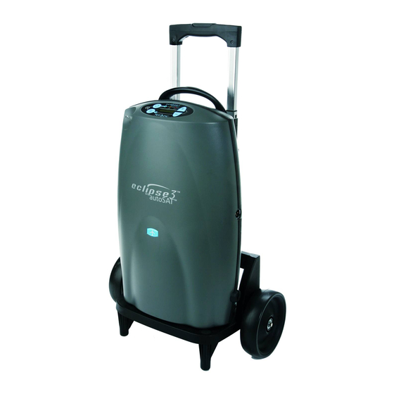
Personal Ambulatory Oxygen System Provider Technical Manual INTRODUCTION TO THE ECLIPSE 3 OXYGEN SYSTEM ECLIPSE 3 AC POWER SUPPLY WITH NEMA POWER CORD PN: 5941-SEQ DC POWER SUPPLY UNIVERSAL CART PN: 5942-SEQ POWER CARTRIDGE (BATTERY) PN: 7082-SEQ PN: 5991-SEQ Control Panel Handle EDAT Service Port (Not for Patient Use) -
Page 6: Eclipse Oxygen System Specifications
ECLIPSE OXYGEN SYSTEM SPECIFICATIONS Personal Ambulatory Oxygen System Provider Technical Manual Oxygen Concentrator 19.3 x 12.3 x 7.1 inches Dimensions (H x W X D) (49.0cm x 31.2cm x 18.0cm) Weight Eclipse 15.0 pounds Power Cartridge 3.4 pounds Flow Settings Continuous Flow 0.5 to 3.0 LPM (0.5 liter increments) (measured in Liters Per Minute LPM) -
Page 7: Pulse Dose Mode Specifications
Personal Ambulatory Oxygen System Provider Technical Manual Pulse Dose Mode Specifications Pulse Settings 1.0 to 6.0, in 16mL increments and 128mL, 160mL, 192mL Trigger Sensitivity Adjustable between settings of 1 (most sensitive) to 3 (least sensitive) Adjustable Bolus Rise Time Adjustable settings of Fast(factory setting), Medium, or Slow •... -
Page 8: Independent Safety Testing
Personal Ambulatory Oxygen System Provider Technical Manual Independent Safety Testing Eclipse System and Eclipse Concentrator, Model 1000B IEC 60601-1 :1988 + A1 :1991 + A2 :1995 + Corrigendum (6/95) Safety EN 60601-1(1990) + A1(1993) + A2(1995) + A12(1993) + A13(1996) + Corrigenda (7/94) FCC 15B (Sec. -
Page 9: Electromagnetic Compatibility
Personal Ambulatory Oxygen System Provider Technical Manual ELECTROMAGNETIC COMPATIBILITY This equipment has been tested and found to comply with the limits for medical devices to the IEC60601-1-2 Electromagnetic Compatibility standard. These limits are designed to provide reasonable protection against harmful interference in a typical medical installation. - Page 10 Personal Ambulatory Oxygen System Provider Technical Manual Guidance and manufacturer’s declaration–electromagnetic immunity The Eclipse 3 is intended for use in the electromagnetic environment specified below. The customer or the user of the Eclipse 3 should assure that it is used in such an environment. Immunity test IEC 60601 test level Compliance level...
- Page 11 Personal Ambulatory Oxygen System Provider Technical Manual Guidance and manufacturer’s declaration–electromagnetic immunity The Eclipse 3 is intended for use in the electromagnetic environment specified below. The customer or the user of the Eclipse 3 should assure that it is used in such an environment. Immunity test IEC 60601 test level Compliance level...
- Page 12 Personal Ambulatory Oxygen System Provider Technical Manual Recommended separation distances between portable and mobile RF communications equipment and the Eclipse 3 The Eclipse 3 is intended for use in an electromagnetic environment in which radiated RF disturbances are controlled. The cus- tomer or the user of the Eclipse 3 can help prevent electromagnetic interference by maintaining a minimum distance between portable and mobile RF communications equipment (transmitters) and the Eclipse 3 as recommended below, according to the maximum output power of the communications equipment.
-
Page 13: How The Eclipse 3 Works
Personal Ambulatory Oxygen System Provider Technical Manual How The Eclipse 3 Works INTRODUCTION The Eclipse 3, Personal Ambulatory Oxygen System with autoSAT Technology is a portable medical device used to extract oxygen from the atmosphere, concentrate it to 87–95.6% and present the oxygen to the patient. The device will operate in Continuous Flow Mode or Pulse Dose Mode. -
Page 14: Compressor And Compressor Enclosure
Personal Ambulatory Oxygen System Provider Technical Manual COMPRESSOR AND COMPRESSOR ENCLOSURE The Eclipse Compressor is a two-cylinder, variable speed wobble piston compressor, driven by a highly efficient Brushless DC (BLDC) motor. When air flows into the Compressor enclosure, it passes through an air intake filter/muffler that muffles sound and filters out impurities. -
Page 15: Control Panel
Personal Ambulatory Oxygen System Provider Technical Manual CONTROL PANEL The control panel provides a user interface consisting of a membrane panel keyboard, Liquid Crystal Display (LCD), external power present indicator, Power Cartridge capacity indicator, alarm status indicators, and an audio transducer. The user interface informs the user of the system status and allows the user to set the desired flow rate and flow mode. - Page 16 Personal Ambulatory Oxygen System Provider Technical Manual USER CONTROLS AND SYSTEM STATUS INDICATORS CONT. Symbol Definition Symbol Definition No Smoking Icon (button): Do not smoke near unit. Providers can access provider mode software functions using the Control Panel. All provider mode information is displayed on the LCD. The software shall FAA approved for use aboard passenger aircraft.
-
Page 17: Continuous Flow Mode
Personal Ambulatory Oxygen System Provider Technical Manual CONTINUOUS FLOW MODE Continuous Flow Mode delivers a constant flow of oxygen to a patient by means of tubing and a nasal cannula at rates between 0.5 LPM and 3.0 LPM. Within the Eclipse, concentrated oxygen is stored in a 500ml product tank at pressures in the range of 5 to 9 psi. -
Page 18: Provider Mode Functions
Personal Ambulatory Oxygen System Provider Technical Manual PROVIDER MODE FUNCTIONS Providers can access provider mode software functions using the Control Panel. All provider mode information is displayed on the LCD. The software shall advance the following Eclipse 3 display mode when the “No Smoking” icon is pressed: •... -
Page 19: Service Mode Functions
Personal Ambulatory Oxygen System Provider Technical Manual SERVICE MODE FUNCTIONS Factory maintenance or service updates may sometimes be required on the Eclipse. Factory and qualified factory-trained technicians can access service mode software functions by using the Service Port located on the back of the unit. The Service Port is not for patient use. -
Page 20: Power Supplies
Personal Ambulatory Oxygen System Provider Technical Manual POWER SUPPLIES The Eclipse may operate from either the AC or DC Power Supply or the Power Cartridge. When power is available from an external supply, the Eclipse will draw from the external source rather than depleting the Power Cartridge. Connection to external power is indicated when the External Power Present Indicator located on the Control Panel is illuminated. -
Page 21: Power Cartridge
Personal Ambulatory Oxygen System Provider Technical Manual Figure 6: Eclipse 3 DC Power Supply Located near the output cord, there is a green LED that is illuminated when the DC Power Supply is supplying 26VDC power. If the LED is not illuminated, there is no input power available. The Power Supply contains protection circuits for output over- current, input over-voltage, and internal over-temperature conditions. - Page 22 Personal Ambulatory Oxygen System Provider Technical Manual The Eclipse Power Cartridge operation time may be affected by several factors such as bolus size, breathing rates, ambient temperature, age of power cartridge and use over time. The table below describes the typical operating time for a new Power Cartridge.
- Page 23 Personal Ambulatory Oxygen System Provider Technical Manual WARNING: DO NOT tamper with, disassemble, crush or heat the Power Cartridge above 140° F (60° C). The Power Cartridge may present a risk of fire or explosion and will void the warranty. CAUTION Store the Power Cartridge in a cool, dry place when not in use.
-
Page 24: Charging Algorithm
Personal Ambulatory Oxygen System Provider Technical Manual CHARGING ALGORITHM The charging algorithm is performed by the Power Manager software and involves three basic decisions: When to start charging How fast to charge When to stop charging Charging begins when Power Cartridge voltage falls below 16.0 volts. The charging current is limited by the charger capability and the rated capacity of the Power Cartridge. -
Page 25: Training The Patient
Personal Ambulatory Oxygen System Provider Technical Manual Training The Patient INTRODUCTION Welcome to the Eclipse 3, Personal Ambulatory Oxygen System with autoSAT Technology. Setting up and training your patient to use the Eclipse has never been easier! You can expect your patients and care providers to easily learn how to use the device by following the directions in this section. -
Page 26: Indications For Use
Personal Ambulatory Oxygen System Provider Technical Manual INDICATIONS FOR USE The Eclipse is indicated for the administration of supplemental oxygen. The device is not intended for life support nor does it provide any patient monitoring capabilities. A physician must prescribe a specific oxygen flow rate setting to meet patients’ individual needs. Recommended oxygen flow rates should be adjusted only under the advice of a physician. -
Page 27: Locating The Eclipse
Personal Ambulatory Oxygen System Provider Technical Manual WARNING: No Smoking or Open Flames. For safety concerns, all possible sources of ignition must be kept away from the oxygen system and preferably out of the room in which it is being used. Smoking in the proximity of an operating oxygen concentrator is dangerous and can permanently damage the device and void the warranty. -
Page 28: Showing Power Cartridge Power Level
Personal Ambulatory Oxygen System Provider Technical Manual SHOWING POWER CARTRIDGE POWER LEVEL The display on the Control Panel shows the amount of Power Cartridge capacity available and waterfalls when charging. Point out the table showing typical new Power Cartridge duration-of-use time in the Users Manual. WARNING: The display gives an approximate level of remaining battery power. -
Page 29: Battery Conservation Feature
Personal Ambulatory Oxygen System Provider Technical Manual ‘POWER CARTRIDGE (BATTERY) CONSERVATION’ FEATURE While in Pulse Dose Mode, the Eclipse 3 is always monitoring for breath detection. After 15 seconds of no breath detected, the Eclipse 3 “delivers” Continuous Flow at the last Continuous Flow setting. The system and display are still in Pulse Dose Mode and the green Delivery Mode Indicator is blinking fast, indicating you are receiving a Continuous Flow. -
Page 30: Adjusting Rise Time
Personal Ambulatory Oxygen System Provider Technical Manual ADJUSTING RISE TIME The adjustable Rise Time feature on the Eclipse 3 was designed for patient comfort. The Rise Time feature adjusts flow and speed of bolus delivery, and determines how quickly the patient receives their bolus volume while in Pulse Dose Mode. The Eclipse 3 offers delivery settings of FAST, MEDIUM, and SLOW. -
Page 31: Connecting The Dc Power Supply
Personal Ambulatory Oxygen System Provider Technical Manual CONNECTING THE DC POWER SUPPLY To install the DC Power Supply, follow these steps: A DC Power Supply allows the system to operate from DC outlets, such as those found in motor vehicles. CAUTION The DC Power Supply is designed for 12VDC minimum vehicle electrical systems. -
Page 32: Attach The Universal Cart
Personal Ambulatory Oxygen System Provider Technical Manual CAUTION Always check to see that the Air Inlet and the Exhaust Vent are not blocked and the Air Inlet Filter is dry and clean before using your Eclipse. • Do not drop the Eclipse or Eclipse power supplies. If dropped or damaged, verify unit performance. - Page 33 Personal Ambulatory Oxygen System Provider Technical Manual CAUTION Be sure to accurately determine the amount of current the vehicle accessory outlet is rated to supply. WARNING: • Avoid placing the Eclipse in direct sunlight. • Do not store the Eclipse in a vehicle where the device may be subject to extreme temperatures.
-
Page 34: Traveling By Air
Personal Ambulatory Oxygen System Provider Technical Manual TRAVELING BY AIR TRAVEL APPROVED The Eclipse is an FAA approved portable concentrator. A new US Department of Transportation regulation regarding portable oxygen concentrators took effect on May 13, 2009. Under this regulation, every FAA approved portable concentrator is now authorized for use during any commercial flight that departs or arrives in the USA, regardless of whether the airline itself has approved the device or not. -
Page 35: Eclipse Maintenance
Personal Ambulatory Oxygen System Provider Technical Manual ECLIPSE MAINTENANCE WEEKLY MAINTENANCE—PATIENT Training your patient to maintain the Eclipse properly will lead to longer service intervals and lower maintenance costs. Train your patient to perform the following procedures: CLEAN THE AIR INLET FILTER The Air Inlet Filter, located at the rear of the unit, must be cleaned at least once a week. -
Page 36: Monthly Maintenance-Patient
Personal Ambulatory Oxygen System Provider Technical Manual MONTHLY MAINTENANCE—PATIENT CARE FOR THE POWER CARTRIDGE The Power Cartridge (battery) in the Eclipse requires special care to assure a longer life and the highest level of performance. The SeQual Power Cartridge is the only approved Power Cartridge recommended for use with the Eclipse. The following are generic guidelines for the Power Cartridge: •... -
Page 37: Patient Training Checklist
PATIENT TRAINING CHECKLIST Use the following checklist as a guide to assist in setup and training a patient on the use of the Eclipse 3 with autoSAT Technology and its accessories. ™ ® Patient Name: Eclipse Serial # DC Power Supply Serial # AC Power Supply Serial # Power Cartridge Serial # Training Topic... -
Page 38: Annual Maintenance-Provider
Personal Ambulatory Oxygen System Provider Technical Manual Annual Maintenance—Provider INTRODUCTION Properly maintaining the Eclipse will ensure longer life and higher performance. Minimum annual maintenance is required. CAUTION The Eclipse contains electrostatic sensitive components. Do not open or handle except at a static free workstation. Do not remove cover without ESD protection. -
Page 39: Annual Maintenance Procedures
Personal Ambulatory Oxygen System Provider Technical Manual ANNUAL MAINTENANCE PROCEDURES The following section lists procedures that are necessary to maintain the Eclipse. Service should only be performed by a qualified technician. To perform periodic maintenance, the only tools that should be necessary are: •... - Page 40 Personal Ambulatory Oxygen System Provider Technical Manual CAUTION The Eclipse contains electrostatic sensitive components. Do not open or handle except at a static free workstation. Do not remove cover without ESD protection. Screws Figure 12: Removing screws to open the Front Cover Turn over and place the unit horizontally on the back cover.
- Page 41 Personal Ambulatory Oxygen System Provider Technical Manual 6. Disconnect the cable from the Control Panel as follows: Grasp the circuit board firmly between your fore fingers and thumb. b. Grasp the head of the Membrane Panel Overlay cable in your other hand. Firmly pull the cable away from the board.
- Page 42 Personal Ambulatory Oxygen System Provider Technical Manual Cut Cable Tie Figure 15: Disconnecting the Oxygen Outlet Tube 8. Lay the front panel away from Eclipse. Inspect PEM Nut anchors in the front cover assembly. Perform necessary maintenance. Figure 16: Front Cover Removal Once the cover has been removed, the procedures listed in this section may be performed.
-
Page 43: Remove And Replace 9 Volt Battery
Personal Ambulatory Oxygen System Provider Technical Manual REMOVE AND REPLACE 9 VOLT BATTERY Replace the 9-volt battery when the unit beeps three times at the end of power-on self-test, when voltage is less than 7.0 Volts, or during annual PM. To replace the 9-volt battery, follow these steps: WARNING: Disconnect power supplies and remove Power Cartridge before removing the unit cover. -
Page 44: Remove And Replace Hepa Filter
Personal Ambulatory Oxygen System Provider Technical Manual REMOVE AND REPLACE HEPA FILTER (Internal and External Filters) Replace the HEPA filter annually, or more often as needed. To replace the HEPA filter, follow these steps. DO NOT use any petroleum based or other lubricants. A spontaneous WARNING: and violent ignition may occur if oil, grease or other petroleum substances come into contact with oxygen under pressure. -
Page 45: Internal Filters (Newer E3S)
Personal Ambulatory Oxygen System Provider Technical Manual 4. Reconnect silicone tubes to the filter. Verify flow direction is correct. Ensure that the feed tubes are not blocked, crimped or kinked upon completion of the installation or the unit will alarm for no/low oxygen flow after the warm-up cycle is complete. - Page 46 Personal Ambulatory Oxygen System Provider Technical Manual 2. Unscrew the wing nut that hold the HEPA filter. Figure 23: Wing Nut. 3. Unscrew the Clear HEPA filter and discard Filter & small O-Ring. Figure 24: Unscrewing the HEPA Filter. 4. Install the new small O-ring and HEPA filter. Figure 25 Installing the new HEPA Filter.
-
Page 47: Remove And Replace The Compressor Intake Filter
Personal Ambulatory Oxygen System Provider Technical Manual 5. Locate the large O-ring on the product tank, replace it with the new large O-Ring included in the PM kit (5022-SEQ). Screw the new HEPA filter into the carriage holder (wing nut topped housing). Insert and screw the new HEPA filter (wing nut topped housing) into the Carriage holder (product tank) and finger snug in place (do not over-tighten). - Page 48 Personal Ambulatory Oxygen System Provider Technical Manual To replace the compressor intake filter, follow these steps: 1. Cut the cable tie on the silicone tubes attached to the compressor intake filter. Figure 27: Removing the Compressor Intake Filter. Remove the silicone tubes attached to each end of the filter body. Install a new filter by pushing each tube completely over the barb on the filter body.
-
Page 49: Reinstalling Or Replacing The Unit Cover
Personal Ambulatory Oxygen System Provider Technical Manual After replacing the Compressor Intake Filter, check the following: • Verify proper seating of the filter in the Eclipse. The arrow on the filter body should point toward the 9-volt battery. • Ensure that the inlet tube is inserted securely into its hole in the compressor box and is not pinched. -
Page 50: Test Procedures
Personal Ambulatory Oxygen System Provider Technical Manual TEST PROCEDURES ECLIPSE PURITY AND FLOW RATE TEST PROCEDURE - PREFERRED METHOD It is recommended that the Eclipse be tested for oxygen concentration and flow performance. The SeQual recommended test setup is shown on the following diagram. Oxygen monitors may or may not have an internal pump to draw samples of oxygen to be measured. -
Page 51: Assembly And Alarm Verification Tests
Personal Ambulatory Oxygen System Provider Technical Manual ASSEMBLY AND ALARM VERIFICATION TESTS To ensure proper assembly and functionality of the Eclipse after it has been reassembled, the following steps should be followed. 1. Install the Power Cartridge into the Power Cartridge compartment of the Eclipse. Plug the AC Power Supply int the wall outlet and connect it to the External Power Connector of the Eclipse. -
Page 52: Record Hours Of Operation & Software Version
Personal Ambulatory Oxygen System Provider Technical Manual RECORD HOURS OF OPERATION AND SOFTWARE VERSION To help maintain the Eclipse, you may obtain the Total Hours of Operation and software version numbers for the Control Board and the Power Manager Systems by following the steps below. Data Output Form Example Alarm Code - If connected to the AC or DC Power Supplies, press... -
Page 53: Electrical Safety Test
Personal Ambulatory Oxygen System Provider Technical Manual ELECTRICAL SAFETY TEST This is required only for the Eclipse 3 Oxygen System, PN 5701-SEQ that utilizes the Hospital Grade Power Cord. To test the basic electrical safety of the Eclipse AC Power Supply, SeQual recommends using an LKG-601 Electrical Safety Analyzer (Netech Corporation, Hicksville, NY) or equivalent to verify that the current leakage to ground is within appropriate limits. -
Page 54: Provider Service And Maintenance Record
Personal Ambulatory Oxygen System Provider Technical Manual PROVIDER SERVICE AND MAINTENANCE RECORD Whenever maintenance or service is performed on an Eclipse unit, an entry should be made in the service log for that concentrator or recorded in accordance with your company’s standard procedure. Whenever the case of the Eclipse is opened, the flow rate, purity, and alarm status should be verified per the Test Procedures in this manual. -
Page 55: Shipping And Transporting The Eclipse
Personal Ambulatory Oxygen System Provider Technical Manual SHIPPING AND TRANSPORTING THE ECLIPSE When shipping the Eclipse use original packaging, if possible. Always remove the Power Cartridge and cart from the Eclipse prior to shipping. If original packaging material is available repack the Eclipse, Power Cartridge, cart and power supplies in the designated packaging areas. -
Page 56: Troubleshooting, Service, And Repair Procedures
Personal Ambulatory Oxygen System Provider Technical Manual Troubleshooting, Service, and Repair Procedures CAUTION The Eclipse contains electrostatic sensitive components. Do not open or handle except at a static free workstation. Do not remove cover without ESD protection. To adaquately troubleshoot and repair the product in the field, EDAT is recommended. NOTE: Eclipse Data Acquisition Tool (EDAT) PN 5535-SEQ... -
Page 57: System Troubleshooting And Alarms
Personal Ambulatory Oxygen System Provider Technical Manual SYSTEM TROUBLESHOOTING AND ALARMS PROVIDER TROUBLESHOOTING TABLE DO NOT IGNORE ALARMS. Symptom Probable Cause Remedy On Start Up (first 5 seconds) The 9V battery (internal to the Eclipse) Replace 9V battery/Perform Annual Preventive Maintenance (5022- - unit beeps 3 times is low SEQ) - Page 58 Personal Ambulatory Oxygen System Provider Technical Manual RED LIGHT Symptom Probable Cause Remedy During Operation: Restricted Air Flow through cabinet Perform Annual Preventive Maintenance (5022-SEQ), if issue remains call Red Light “Blink- inlet filter Chart TS for service. ing” and “3 Beeps” Blocked air flow to cabinet inlet Ensure the Eclipse has adequate air flow around the device (6"...
- Page 59 Personal Ambulatory Oxygen System Provider Technical Manual OTHER CONDITIONS (CONTINUED) Battery Power: My Battery End of Life: May have exceeded Discharge it fully, recharge it fully, then measure the length of discharge to Battery is not Lasting the life expectancy of 500 full Charge/ within 20% of new specification.
-
Page 60: Alarm Conditions And Alarm Codes
Personal Ambulatory Oxygen System Provider Technical Manual ALARM CONDITIONS AND ALARM CODES Use the table below to decode Eclipse alarm conditions. If other alarm codes are displayed by the Eclipse, contact Chart- SeQual Technical Service for assistance. Note: The following table is intended as a guide for the provider, not the user. ALARM ALARM GREEN... -
Page 61: Malfunction Codes
Personal Ambulatory Oxygen System Provider Technical Manual MALFUNCTION CODES If a malfunction occurs in the Eclipse, the device will stop, the Red LED on the front panel will light and the buzzer will sound for 10 seconds and then silence. The LCD will display one of the following Malfunction Codes: Malfunction FAIL code Recommended Action... -
Page 62: System Schematics And Diagrams
Personal Ambulatory Oxygen System Provider Technical Manual System Schematics and Diagrams SIMPLIFIED BLOCK DIAGRAM Figure 31: Eclipse 3 Oxygen System Simplified Block Diagram. Figure 32: Top Case Components. - Page 63 Personal Ambulatory Oxygen System Provider Technical Manual Control Board Module Compressor Intake Filter Compressor Product Tank Power Manager Exhaust PC Board Duct Battery Bridge PC HEPA Board Filter Figure 33: Bottom Case Components.
- Page 64 Personal Ambulatory Oxygen System Provider Technical Manual Control Board Module Compressor Intake Filter Compressor Product Tank Power Manager PC Board Exhaust Duct Battery Bridge PC Board Figure 34: Bottom Case Components—Eclipse 3 Manufactured December 2011 and above...
-
Page 65: Oxygen Circuit
Personal Ambulatory Oxygen System Provider Technical Manual Oxygen Circuit REMOVE AND REPLACE THE ATF MODULE There are no serviceable parts inside the ATF Module. Do not attempt NOTE: to disassemble or modify the ATF Module. Remove the Unit Cover as described in the section Remove and Replace the Unit Cover. Cut the green tie as shown below, and disconnect the silicone tube that goes into the product port of the ATF;... - Page 66 Personal Ambulatory Oxygen System Provider Technical Manual Cut the green cable ties to the braided tubes that connect into the ATF pressure and vacuum ports as shown below. Disconnect the braided tubes. 5a. Install port caps. Unscrew the 3 screws (M4x16 Pan Head Machine Screw, P/N 6961-416) and remove the screws and washers (M4 Flat washer, P/N 6985-04) as shown below.
- Page 67 Personal Ambulatory Oxygen System Provider Technical Manual 16” Silicone Tube Routing Figure 39: Tube Routing under ATF Module. 10. Place the ATF in the Unit Case and remove the caps from the ATF Ports. Install the Braided Tubes into the ATF pressure and vacuum ports as shown on Figure 31. Do not use oil or grease if the tubing is difficult to install.
-
Page 68: Remove And Replace The Product Tank Assembly (Pn 6138-Seq) Eclipse 1, Eclipse 2, Early Eclipse 3
Personal Ambulatory Oxygen System Provider Technical Manual 12. Remove caps from ATF Module. 13. Connect the silicone tube from the Product Tank into the product port of the ATF and secure joints with cable ties as shown on Figure 30 on page 57. 14. - Page 69 Personal Ambulatory Oxygen System Provider Technical Manual Unscrew the 2 screws (M3x10 Plastite Screw, P/N 6950-310) and remove the screws and washers (M3 Flat Washer, P/N 6950-03) as shown in Figure 41 shown below. Pinch Product Cable Outlet Port No Kink Here Screw &...
-
Page 70: Routing Diagram For Pneumatic Tubing
Personal Ambulatory Oxygen System Provider Technical Manual ROUTING DIAGRAM FOR PNEUMATIC TUBING Use the picture below as an aid to ensure proper routing of oxygen tubing in the Eclipse. Tube from Product Tank to Flow/Concentration Tube from ATF Measurement Tube Module to Product (10”... -
Page 71: Remove And Replace The Product Tank Assembly (Pn 4378-Seq) Eclipse 3-2011 In Sn 11F06100456 And Above
Personal Ambulatory Oxygen System Provider Technical Manual REMOVE AND REPLACE THE PRODUCT TANK ASSEMBLY (PN 4378-SEQ) ECLIPSE 3-2011 IN SN 11F06100456 AND ABOVE Situation# 1) If you are “upgrading” from a previous model Product Tank (PN1038-SEQ) you will need to let Tech Support know as the ATF output port is in a different location as it can be different between ATF models (PN: 3995 to PN: 5494). - Page 72 Personal Ambulatory Oxygen System Provider Technical Manual 4) Locate the 2 screws that hold the securing straps and the product tank in place, remove the screws. Set aside for re- installation. Figure 44. Remove Screws Figure 44: Remove Screws 5) Lift out the old product tank(PN: 6138-SEQ). Set aside for RMA return or scrap. Install new Product Tank (PN: SP4378-SEQ or 4378-SEQ) 1) Locate all parts needed: Product Tank, Product Tube from ATF (correct version), Securing arm and screws.
- Page 73 Personal Ambulatory Oxygen System Provider Technical Manual 2) Position the product tank with the 2 hose barbs facing in the direction of the ATF. Refer to Figure 46. Figure 46: Product tank and hose barbs 3) Install the securing arm over the product tank, and locate the screw hole on the back case cover for the old product tank securing arm that was to the right(top side of compressor).
- Page 74 Personal Ambulatory Oxygen System Provider Technical Manual 5) Connect the Output tubing to the Top port on the Product Tank and secure with cable ties. See Figure 48. Add cable tie to both top and bottom parts Figure 48: Connect output tubing Situation# 2: Removing the New Style Product Tank (PN:4378-SEQ) 1) Follow the steps to “Remove and Replace the Front Cover Assy”...
- Page 75 Personal Ambulatory Oxygen System Provider Technical Manual 7) Locate the 2 screws that hold the securing straps and the product tank in place, remove the screws. Set aside for re- installation. Figure 50. Remove screws Fig 50: Remove screws 8) Lift out the old product tank (PN: 4378-SEQ). Set aside for RMA return or scrap. 9) Follow the above step to Install the New Product Tank (PN: SP4378-SEQ) above.
-
Page 76: Electronics
Personal Ambulatory Oxygen System Provider Technical Manual Electronics REMOVE AND REPLACE THE CONTROL BOARD ASSEMBLY CAUTION The Eclipse contains electrostatic sensitive components. Do not open or handle except at a static free workstation. The Control Board Assembly is factory calibrated as a single unit. Do NOTE: not disassemble the Control Board Assembly. - Page 77 Personal Ambulatory Oxygen System Provider Technical Manual Lift the Control Board out of the Unit. Cut the green cable tie to the silicone tube that is connected to the sensor as shown in Figure 51. Disconnect the silicone tube that is attached to the sensor. Cut the green cable ties to the silicone tubes that are connected to the flow tube as shown in Figure 52.
-
Page 78: Remove And Replace The Buzzer Wire Harness
Personal Ambulatory Oxygen System Provider Technical Manual REMOVE AND REPLACE THE BUZZER WIRE HARNESS Unplug the buzzer from the Control Board PC Board. Remove the Control Board. To remove the buzzer from the case, cut the cable tie, grasp the buzzer body with a pair of pliers and rotate the buzzer to break the adhesive joint. -
Page 79: Control Board Connector Diagram
Personal Ambulatory Oxygen System Provider Technical Manual CONTROL BOARD CONNECTOR DIAGRAM Use the figure below as an aid to ensure proper connection of wire harnesses to the Power Manager printed circuit board. Air Inlet Power Control Temperature Manager PC Board Panel Communications Data... -
Page 80: Remove And Replace The Power Manager Printed Circuit Board
Personal Ambulatory Oxygen System Provider Technical Manual REMOVE AND REPLACE THE POWER MANAGER PRINTED CIRCUIT BOARD CAUTION The Eclipse contains electrostatic sensitive components. Do not open or handle except at a static free workstation. Remove the Power Cartridge and unscrew the 4 screws (M3x12 Pan Head SEM Screw, P/N 6974-312-SEQ) shown in Figure 56. - Page 81 Personal Ambulatory Oxygen System Provider Technical Manual Disconnect the 5 wire harnesses as shown in Figure 49. Remove the Battery Bridge PCB as shown in Figure 57. Battery Bridge Screw Board External Power Wire Harness Blower Wire Harness Cooling Fan Wire Harness Compressor Power Compressor Signal...
- Page 82 Personal Ambulatory Oxygen System Provider Technical Manual Pull the Power Manager PCB 1” out of the unit case. Gently push the Compressor Box away from the Power Manager PCB by 1/8”. Disconnect the 2 wire harnesses and the ribbon cable shown in Figure 59. Remove the Power Manager PC Board.
-
Page 83: Power Manager Pc Board Connector Diagram
Personal Ambulatory Oxygen System Provider Technical Manual POWER MANAGER PC BOARD CONNECTOR DIAGRAM Use the picture below as an aid to ensure proper connection of wire harnesses to the Power Manager printed circuit board. Compressor Compressor Blower Power External Power Cooling Battery Compressor... -
Page 84: Power Manager Pcb Identification
Personal Ambulatory Oxygen System Provider Technical Manual POWER MANAGER PCB IDENTIFICATION Use the picture below as an aid to ensure proper connection of wire harnesses to the Power Manager printed circuit board. Figure 61: Previous - Separate PM pcb and BBB pcb (PN: SP3986-1-SEQ) Figure 62: New Combo PM/BBB pcb (5932-1-SEQ) - Page 85 Personal Ambulatory Oxygen System Provider Technical Manual A Procedure to replace the new Combo Power Manager Board and Battery Bridge Board: 1 Remove and Replace Combo Power Manager board set WARNING: Disconnect power supplies and remove Power Cartridge before removing the unit cover. Do not touch exposed circuits during maintenance without ESD protection.
- Page 86 Personal Ambulatory Oxygen System Provider Technical Manual 1.4 Unscrew the 2 Cooling Fan screws (PN: 6961-21-SEQ) holding the fan in place. Remove the Fan (PN: 1074-SEQ). Set aside for later installation. 1.5 Remove the Exhaust tube in Figure 65. Set aside for later installation. Exhaust Tube Fig 65: Exhaust Tube 1.6 Pull the Power Manager pcb 1”...
- Page 87 Personal Ambulatory Oxygen System Provider Technical Manual 1.7 Unbox the SP5932-1-SEQ and account for all parts (Fig 67). Fig 67: New Power Manager 1.8 Position the New Power Manager PCB(PN: 5932-1-SEQ) 1” out of the case as shown in Fig 58. Gently push the Compressor Box away from the Power Manager pcb by 1/8”.
- Page 88 Personal Ambulatory Oxygen System Provider Technical Manual 1.8 Install the Cooling Fan (PN: 1074-SEQ) with the 2 screws (PN: 6961-210-SEQ) and lightly tighten as shown in Fig 69. Apply Loctite 425 thread locker on the tips of the threads before installing. Note: Ensure the cooling fan is blowing down as indicated by the arrow on the side of the fan.
-
Page 89: Compressor
Personal Ambulatory Oxygen System Provider Technical Manual Compressor As with any concentrator, the compressor is a limited-wear component and may require servicing during the lifetime of the device. The point of service will be dependent on factors such as operation time, flow settings and environmental conditions. - Page 90 Personal Ambulatory Oxygen System Provider Technical Manual Disconnect the 3 wire harnesses shown in Figure 72. Blower Wire Harness Compressor Power Compressor Signal Wire Harness Wire Harness Figure 72: Compressor Box electrical connections. Remove the Exhaust Tube as shown in Figure 73. Exhaust Verify Engagement Tube...
- Page 91 Personal Ambulatory Oxygen System Provider Technical Manual Cut the three green cable ties shown in Figure 74. Disconnect the two braided hoses from the pressure and vacuum ports of the ATF. Cap the three ATF module ports using tight fitting vinyl caps or vinyl electrical tape.
- Page 92 Personal Ambulatory Oxygen System Provider Technical Manual Turn the unit over onto a padded ESD safe surface and remove the 4 screws (M4x16 Pan Head Machine Screw , PN 6961-420-SEQ) and washers (M4 Flat Fender Washer, PN 3568-SEQ) shown in Figure 75. Screws Washers (4 Places)
-
Page 93: Preventative Maintenance Parts
Personal Ambulatory Oxygen System Provider Technical Manual MAINTENANCE AND REPLACEMENT PARTS Preventative Maintenance Parts Description SeQual Part Number Preventive Maintenance Kit (includes * items) 5022-SEQ * Air Inlet Filter 7028-SEQ * Compressor Intake Filter 8069-SEQ * HEPA Filter (Old /New) 6986-SEQ / 9765-SEQ * 9V Battery 8098-SEQ... -
Page 94: Optional Accessories
Personal Ambulatory Oxygen System Provider Technical Manual ECLIPSE OPTIONAL ACCESSORIES Visit us at www.sequal.com for more information about optional accessories. There are many different types of oxygen tubing, cannula, and humidifiers. The following items are recommended by SeQual Technologies for use with the Eclipse. Salter Labs Humidifier, Part Number 7600, or equivalent: If your physician has prescribed an optional humidifier, follow ®... -
Page 95: Information
Personal Ambulatory Oxygen System Provider Technical Manual CHART CAIRE CUSTOMER SERVICE CONTACT INFORMATION If you need any additional assistance, contact CAIRE: By mail: CAIRE Inc. 2200 Airport Industrial Drive, Suite 500 Ball Ground, GA 30107 USA By telephone: 800.482.2473 By E-mail: techservice.usa@chart-ind.com www.CAIREmedical.com...
Need help?
Do you have a question about the 1000B and is the answer not in the manual?
Questions and answers
What is an alarm 8? What is an alarm 4?