Table of Contents
Advertisement
INSTALLATION AND OPERATING INSTRUCTIONS
11'5"
13'10"
25'9"
25' 10"
KidKraft, Inc.
4630 Olin Road
Dallas, Texas 75244 USA
customerservice@kidkraft.com
canadacustomerservice@kidkraft.com
1.800.933.0771
972.385.0100
For online parts replacement visit
https://parts.kidkraft.com/
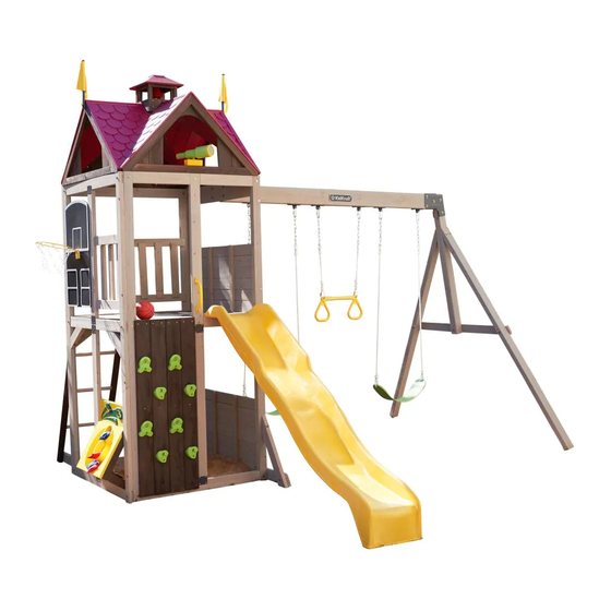
Summerhill Playset – F29050
WARNING
any future owner of this play system. Manufacturer contact information provided below.
OBSTACLE FREE SAFETY ZONE - 25'10" x 27' area requires Protective Surfacing. See Page 3
MAXIMUM VERTICAL FALL HEIGHT - 6'9"(2.06m)
27'
- 10
CAPACITY
RESIDENTIAL HOME USE ONLY. Not intended for public areas such as schools, churches,
nurseries, day cares or parks.
Warning. Only for domestic use.
KidKraft Netherlands BV
Olympisch Stadion 29
1076DE Amsterdam
The Netherlands
europecustomerservice@kidkraft.com
+31 20 305 8620 M-F from 09:00 to 17:30
(GMT+1)
For online parts replacement visit
https://parts.kidkraft.eu/
To reduce the risk of serious injury or death, you
must read and follow these instructions. Keep and
refer to these instructions often and give them to
Users Maximum, Ages 3 to 10; Weight Limit 110 lbs. (49.9 kg) per child.
TWO PERSON
ASSEMBLY
Table of Contents
Warnings And Safe Play Instructions . . . . . . . . . . pg . 2
Protective Surfacing Guidelines . . . . . . . . . . . . . . . pg . 3
Instructions For Proper Maintenance . . . . . . . . . pg . 4
About Our Wood – Limited Warranty . . . . . . . . . pg . 5
Keys To Assembly Success . . . . . . . . . . . . . . . . . . . . pg . 6
Part ID . . . . . . . . . . . . . . . . . . . . . . . . . . . . . . . . . . . pg . 8-15
Step-By-Step Instructions . . . . . . . . . . . . . . . pg . 16-64
Installation of I . D . / Warning Plaque . . . . . .Final Step
12 - 16 Hrs
Rev 09/12/2018
Advertisement
Table of Contents

Related Manuals for KidKraft Summerhill F29050


Summary of Contents for KidKraft Summerhill F29050
- Page 1 KidKraft, Inc. KidKraft Netherlands BV Keys to Assembly Success . . . . . . . . . . . . . . . . . . . . pg . 6...
- Page 2 Warnings and Safe Play Instructions CONTINUOUS ADULT SUPERVISION REQUIRED. Most serious injuries and deaths on playground equipment have occurred while children were unsupervised! Our products are designed to meet mandatory and voluntary safety standards. Complying with all warnings and recommendations in these instructions will reduce the risk of serious or fatal injury to children using this play system.
- Page 3 Protective Surfacing - Reducing Risk of Serious Head Injury From Falls. One of the most important things you can do to reduce the likelihood of serious head injuries is to install shock-absorbing protective surfacing under and around your play equipment. The protective surfacing should be applied to a depth that is suitable for the equipment height in accordance with ASTM F1292.
- Page 4 Instructions for Proper Maintenance Your KidKraft Play System is designed and constructed of quality materials with your child’s safety in mind. As with all outdoor products used by children, it will weather and wear. To maximize the enjoyment, safety and life of your Play Set, it is important that you, the owner, properly maintain it.
- Page 5 About Our Wood KidKraft Premium Play Systems uses only premium playset lumber, ensuring the safest product for your children’s use. Although we take great care in selecting the best quality lumber available, wood is still a product of nature and susceptible to weathering which can change the appearance of your set.
- Page 6 Keys to Assembly Success Tools Required • Tape Measure • #1, #2 & #3 Phillips • Open End Wrench • 3/16” Hex Key • Carpenters Level or Robertson Bits (7/16”, 1/2” & 9/16”) • 8’ Step Ladder • Carpenters Square or Screwdriver •...
- Page 8 Part Identification (Reduced Part Size) Part Identification (Reduced Part Size) Part Identification (Reduced Part Size) Part Identification (Reduced Part Size) 4pc. - 2850 - 31.8 x 76.2 x 304.8mm - Tower Gusset 3pc. - 1578 - 28.6 x 403.2mm - Dowel -Tennon 3562850 3681578 - Box 1 -...
- Page 9 Part Identification (Reduced Part Size) Part Identification (Reduced Part Size) Part Identification (Reduced Part Size) Part Identification (Reduced Part Size) 3562616 1pc. - 2616 - 23.8 x 82.6 x 1181.1mm - SW Support - Box 1 - 4pc. - 2851 - 15.9 x 114.3 x 1193.8mm - Vertical Rock Board - Box 1 - 3582851 3562615 1pc.
- Page 10 Part Identification (Reduced Part Size) Part Identification (Reduced Part Size) Part Identification (Reduced Part Size) Part Identification (Reduced Part Size) 1pc. - 2627 - 31.8 x 1066.8 x 2209.8 mm - SW Wall Panel - Box 1 - 37562627...
- Page 11 Hardware Identification (Actual Size) 5pc. LW2 28pc. TN1 - 1/4" T - Nut (54303200) 42pc. FW1 8pc. FW0 5/16" Lock Washer 1/4" Flat Washer 3/16" Flat Washer (51303300) (51103200) (51103100) 36pc. LW1 54pc. FW2 - 5/16" Flat Washer - (51103300) 1/4"...
- Page 12 (7310248) 1x - Kidkraft 1x - Rebar Ground ID Plaque Stake (6 Pk) (9320370) (3200318) 1x - KidKraft Plaque (3320353) 2x - Rocks (4 Pk) (3322384) -Green Gecko 2x - Acro Handle (9320231) Yellow 1x - Acro Bar 1x - Jamb Mount (6Pk)
- Page 13 Part Identification (Reduced Part Size) Part Identification (Reduced Part Size) 3582839 1pc. - 2839 - 12.7 x 57.2 x 428.6mm - Bottom - Box 1 - 3582837 2pc. - 2837 - 25.4 x 57.2 x 355.6mm - Diagonal - Box 1 - 3582838 2pc.
- Page 14 Hardware Identification (Actual Size) 2pc. FW1 1/4" Flat Washer (51103200) #8 x 1" 8pc. S33 - Wood Screw - (52043510) #8 x 1-1/2" 104pc. S2 - Wood Screw - (52043512) #8 x 2" 28pc. S11 - Wood Screw - (52043522) #8 x 2-1/2"...
- Page 15 Part Identification (Reduced Part Size) Part Identification (Reduced Part Size) Part Identification (Reduced Part Size) Part Identification (Reduced Part Size) - Basketball Backboard with Pinch Guard (3330740) - Hoop Net and Ball - Telescope w Mount (3330052) (3322361) - Toss Game Add-On (3332350) - Flag and Pole (2pk)(3320232)
- Page 16 Before you discard your cartons fill out the form below. • The carton I.D. stamp is located on the end of each carton.The tracking number is located on the KidKraft ID Plaque (9320370). • Please retain this information for future reference. You will need this information if you contact the Consumer Relations Department.
- Page 17 Step 2: Front and Back Wall Prep Part 1 It is important to assemble the frame on a flat, smooth surface. A: Place (2771) End Post and (2770) End Post Left side by side with the grooves facing up and in. Put (2770) End Post Left on the right hand side.
- Page 18 Step 2: Front and Back Wall Prep Part 2 It is important to assemble the frame on a flat, smooth surface. D: Turn the assembly over, place (2774) Upright in the middle grooves of (2775) Panel Cross Support and (2772) Panel Floor Support then attach all boards with 8 (H9) Hex Bolts (with lock washer and flat washer) connecting to the previously installed t-nuts.
- Page 19 Step 3: End Wall Prep Part 1 It is important to assemble the frame on a flat, smooth surface. A: Place (2768) Panel Floor and 2 (2769) Panel BT Frames on a hard, flat surface with the long side up. Tap in 2 (TN1) T-nuts per board.
- Page 20 Step 3: End Wall Prep Part 2 It is important to assemble the frame on a flat, smooth surface. D: Turn the assembly over then attach all boards with 6 (H9) 1/4 x 1-1/4” Hex Bolts (with lock washer and flat washer) connecting to the previously installed t-nuts.
- Page 21 Step 4: Frame Assembly Part 1 It is important to assemble the frame on a flat, smooth surface. A: Place (2627) SW Wall Panel between 2 Front and Back Walls from Step 2, noticing the wall orientations. The tops and bottoms of the walls should be flush. Make sure the walls are square then using the pilot holes as a guide pre-drill with a 3/16”...
- Page 22 Step 4: Frame Assembly Part 2 B: Place End Wall from Step 3 between the Front Wall and Back Wall noticing the wall orientation. The tops and bottoms of the walls should be flush. Make sure the walls are square then using the pilot holes as a guide predrill with a 3/16”...
- Page 23 Step 4: Frame Assembly Part 3 C: Loosely attach 1 (2607) Diagonal to (2606) SW Ground with 1 (H10) 1/4 x 2-1/4” Hex Bolt (with lock washer, flat washer and t-nut). (fig.4.6) D: Place (2606) SW Ground against the front right side of the (2627) SW Wall Panel making sure that the (2607) Diagonal lines up with the edge of the panel as shown in fig.
- Page 24 Step 5: Floor Assembly Part 1 A: From inside of the assembly centre (2608) Floor Joist over the pilot holes in both (2768) Panel Floors in the Swing and End Walls, measure 5/8” (15.9 mm) down from the top of boards then attach (2608) Floor Joist to each board using the left and centre holes with 2 (S4) #8 x 3”...
- Page 25 Step 5: Floor Assembly Part 2 B: On the inside of both the Front and Back Walls loosely attach 1 (2610) Side Joist to each (2772) Panel Floor Support with 2 (H11) 1/4 x 2-3/4” Hex Bolts (with lock washer, flat washer and t-nut) as shown in fig. 5.5. Make sure both (2610) Side Joist are level with (2608) Floor Joist.
- Page 26 Step 5: Floor Assembly Part 3 C: Fasten each (2610) Side Joist to each (2772) Panel Floor Support with 4 (S3) #8 x 2-1/2” Wood Screws per board as shown in fig. 5.6. D: Tighten all (H11) 1/4 x 2-3/4” Hex Bolts in both (2610) Side Joist. Fig.
- Page 27 Step 5: Floor Assembly Part 4 E: Starting at (2627) SW Wall Panel place (2648) Floor Board followed by 8 (2609) Floor Boards. Make sure all boards are evenly spaced then attach to (2608) Floor Joist and each (2610) Side Joist with 5 (S2) #8 x 1-1/2” Wood Screws per board.
- Page 28 6.3. IT IS IMPORTANT THAT THIS BOLT IS ATTACHED. IT WILL MINIMIZE CHECKING OF WOOD. D: Attach KidKraft Plaque to centre of (2614) Engineered Beam (over top of t-nut) using 4 (S18) #6 x 1” Wood Screws. (fig. 6.4) Fig.
- Page 29 Step 7: Swing End Assembly A: Loosely attach 2 (2613) Heavy SW Posts to (2615) SW Upright using 2 (G7) 5/16 x 5-1/2” Hex Bolts (with lock washer, flat washer and t-nut). Notice 2 bolt holes at top of (2615) SW Upright and orientation of angle. (fig.
- Page 30 Step 8: Attach Swing End to Swing Beam A: Place Swing End Assembly against Swing Beam Assembly then place 1 Beam Bracket on each side of the assembly (they are specific for left and right side) and attach with 5 (G21) 5/16 x 3-3/4” Hex Bolts (with 2 flat washers and 1 lock nut).
- Page 31 Step 9: Attach Swing Assembly To Fort A: Place Swing Assembly against top of (2627) SW Wall Panel, make sure assembly is level then attach from inside the fort assembly into each L-Beam Bracket with 4 (G27) 5/16 x 1 ¾” Hex Bolts (with 2 flat washers and 1 lock nut).
- Page 32 Step 10: Install Ground Stakes MOVE FORT TO FINAL LOCATION PRIOR TO STAKING FINAL LOCATION MUST BE LEVEL GROUND A: In the 5 places shown in (fig.10.1) drive the Rebar Ground Stakes 13” (330mm) into the ground against outside front corner of End Wall Assembly, on both (2607) Diagonals and both (2613) Heavy SW Posts. Be careful not to hit the washer while hammering stakes into the ground as this could cause the washer to break off.
- Page 33 Step 11: Install Upper and Lower Jambs A: In the upper opening of End Wall Assembly place 1 (2602) Upper Jamb so it measures 17”(432mm) to the inside of each post then attach with 2 Jamb Mounts using 4 (S0) #8 x 7/8” Truss Screws per mount. (fig. 11.1 &11.2 &...
- Page 34 Step 12: Install Tower Gussets A: On the Back Wall, place 2 (2850) Tower Gussets so they are flat against the (2772) Panel Floor Support and to the insides of the (2771) End Post and (2770) End Post Left. Attach using 1 (S11) #8 x 2” Wood Screw Wood and 1 (S4) #8 x 3”...
- Page 35 Step 13: Access Ladder Assembly Part 1 A: Insert 3 (1578) Dowels into (2846) Ladder Rail Right and (2845) Ladder Rail Left, as shown in fig. 13.1. Making sure that the holes in both rails are at the top, facing outwards. B: Make sure shoulder of dowel is against each rail before pre-drilling pilot holes.
- Page 36 Step 13: Access Ladder Assembly Part 2 D: On the Back Wall of the assembly and to the right, place Ladder Assembly against (2618) as shown in fig. 13.5 making sure that it is flush. Pre-drill holes with a 1/8”(3.2mm) drill bit then attach using 2 (LS3) 1/4 x 3” Lag Bolt (with flat washer).
- Page 37 Step 13: Access Ladder Assembly Part 3 E: On the inside bottom of (2846) Ladder Rail Right attach 1 (9195) Ladder Brace using 2 (S11) #8 x 2” Wood Screws keeping it flush to (2769) Panel BT Frame. (fig. 13.7 and 13.8) F: From inside the Fort measure approximately 3”...
- Page 38 Step 14: Vertical Wall Assembly Part 1 4X Vert Rock Board (note orientation, every other A: On the lower left hand side of the Front Wall place 4 (2851) Vertical Rock Boards tight together making sure board is flipped) that they are centered in the opening and flush to the top. It is important to note hole orientation, every other 16X #8 x 1-1/2"...
- Page 39 Step 14: Vertical Wall Assembly Part 2 C: Alternating shapes, attach 2 rocks to each (2851) Vertical Rock Board using 1 (PB2) ¼ x 1-1/4” Pan Bolt (with ¼” lock washer, 3/16” flat washer and ¼” barrel nut) and 1 (S10) #8 x 1” Pan Screw per rock. The Pan Screw is placed in the hole beneath the Pan Bolt.
- Page 40 Step 15: Attach Hand Grips A: On the (2774) Upright measure 2”(50.8mm) up from the top of the Vertical Rock Boards and center 1 Hand Grip on the post. Pre-drill with a 1/8”(3.2mm) drill bit and attach using 2 (LS1) ¼ x 1-1/2” Lag Screw (with flat washers).
- Page 41 Step 16: Attach Slide to Fort A: Place Slide in the center of the opening on the front right of the fort as shown in fig. 16.1, pre-drill with a 1/8” (3.2 mm) drill bit then attach slide to fort through the (2772) Panel Floor Support using 3 (S7) #12 x 2” Pan Screws.
- Page 42 Step 17: Lower Jamb Assembly A: In the lower opening of the End Panel place 1 (2601) Lower Jamb so it measures 17” (432mm) to the inside of each post then attach (2601) Lower Jamb with 2 Jamb Mounts using 4 (S0) #8 x 7/8” Truss Screws per mount. (fig.
- Page 43 Step 18: Banister Assembly View Series (except Cloud) A: From inside the fort on the top Left hand side of the End Wall measure 3”(76.2mm) up from the top of the floor boards. Attach 1 (2844) Horizontal using 4 (S2) #8 x 1-1/2” Wood Screws. (fig. 18.1 and 18.2) B: Measure 15”(381mm) up from the top of the (2844) Horizontal installed in Step A and install a second (2844) Horizontal using 4 (S2) #8 x 1-1/2”...
- Page 44 Step 19: Gable End Assembly Part 1 A: Attach one (2852) Roof End to a second (2852) Roof End at peak using 1 (S3) #8 x 2-1/2” Wood Screw. (Fig. 19.1) B: Place 1 (2853) Roof Support between the Roof Ends so the bottom of the Roof Support is flush with the bottoms of each Roof End.
- Page 45 Step 19: Gable End Assembly Part 2 D: From the peak of the gable assembly measure approximately 3” (80.37mm) down and attach 1 (2843) Gable Board C using 4 (S2) #8 x 1-1/2” Wood Screws as shown in (fig. 52.3 and 52.4). There should be maintaining a 1”...
- Page 46 Step 20: Attach Gables to Fort flush A: Center 1 Gable Assembly on the top of each wall panel as shown in fig. 20.2 making sure that the assemblies are flush with the front of the wall panels. Attach each Gable Assembly to the panel using 4 (S4) #8 x 3” Wood 4X #8 x 3"...
- Page 47 Step 21: Attach Roof Panels Part 1 Note: It is important to ensure that there is a 5mm square opening in the top, center of the roof. This will be used in a later step. Build 4 of these assemblies Build 4 of these assemblies A: Bend roof panel along the fold to allow the panel to fit between the gables.
- Page 48 **other gables hidden for clarity** 2X #8 x 1-1/2" WS per roof Step 21: Attach Roof Panels Begin with two gable assemblies and assemble Part 2 as shown note: this hole D: Take a second roof panel and fit the connector tabs so they are coupled with the panel that was previously **other gables hidden for clarity** 2X #8 x 1-1/2"...
- Page 49 Step 21: Attach Roof Panels Part 3 E: Repeat all steps to complete the roof assembly, making sure that a 5mm square opening is left in the center of the roof assembly. (fig. 21.9, 21.10 and 21.11) Fig. 21.9 continue with the other 3 assemblies leaving a 5mm square opening in the centre...
- Page 50 Step 22: Cupola Assembly Part 1 A: Place Weather Vane Base onto Roof Mount so that the holes line up as shown in fig. 22.1. Attach using 2 (S37) #7 x 5/8” Pan Screw. B: Slide each (2940) Cupola Roof section between Base and Roof Mount. Tape sections together in 4 places as shown in fig.
- Page 51 Step 22: Cupola Assembly Part 2 D: Place 1 (2936A) Bell Cupola Side on each side of 1 (2938) Cupola Side Base with the open side of the Cupola Side Base facing the bottom. Make sure that the Cupola Posts and Cupola Side Base are flush at the bottom and attach using 4 (TS) #6 x 30mm Trim Screws.
- Page 52 Step 22: Cupola Assembly Part 3 A: Place Steel Cupola Mount over the Bell. From inside the Bell push the Bell Clapper with screw upwards so that it is going through the Bell and the center hole on the Cupola Mount. Install the Bell Nut to secure into place. (fig.
- Page 53 Step 23: Attach Cupola Part 1 A: Place 2 (2939) Mount Blocks (fig. 23.3 and 23.4) over the top of the roof so that the holes lines up with the starter holes in the panel. Attach using 4 (S2) #8 x 1-1/2 Wood Screws. (fig. 23.1, 23.2, 23.3 and 23.4) screw holes in mount block 2939 line up to starter holes in roof...
- Page 54 Step 23: Attach Cupola Part 2 B: Place Cupola Assembly over both Mount Blocks and attach as shown in fig. 23.5 using 4 (TS) #6 x 30mm Trim Screws. C: Pull string for bell through the square hole in the roof assembly. (fig. 23.6) Cupola Assembly Fig.
- Page 55 Step 24: Attach Telescope A: On the front panel center the telescope on the (2853) Roof Support and attach using 2 (S2) #8 x 1-1/2” Wood Screws. (Fig. 24.1 and fig. 24.2) Fig. 24.1 Telescope 1-3/4" WS 2853 2X #8 x 1-3/4" WS Telescope Fig.
- Page 56 Step 25: Attach Flags A: On the Swing Wall panel and the End Wall Panel attach 1 Flag per side at the top corners of the Gable Assembly using 2 (S10) #8 x 1” Pan Screws per flag. (Fig. 25.2) 2X #8 x 1-3/4"...
- Page 57 Step 26: Install Basketball Net Part 1 A: Hold Hoop against the front of the Backboard and place the Backplate behind as shown in fig. 26.1. Insert the supplied 3 Carriage Bolts and Lock Nuts through the Hoop, Backboard and Backplate and attach. (fig. 26.1 and 26.3) B: Loop the Net around Hoop clips.
- Page 58 Step 26: Install Basketball Net Part 2 C: In the location shown in (Fig.26.4), measure 3.25” (82.6mm) up from the floor and install Backboard to Fort using 8 (S33) #8 x 1” Wood Screws. (Fig. 26.3, 26.4 and 26.5) Fig. 26.3 Fig.
- Page 59 Step 26: Install Basketball Net Part 3 D: From inside the fort place 1 (2844) Horizontal behind the Backboard as shown in fig. 26.6 and attach to (2771) Post and (2602) Upper Jamb using 4 (S2) #8 x 1-1/2” Wood Screws. (fig. 26.6) Inside View Fig.
- Page 60 Step 27: Assemble Bean Bag Toss Part 1 A: Place 1 (2838) Leg flush to 1 (2837) Diagonal as shown, note the board orientation. Pre-drill holes in (2838) Leg using a 1/8” (3.2mm) drill bit and attach (2837) Diagonal using 2 (S4) #8 x 3” Wood Screws. Repeat step to make a second assembly.
- Page 61 Step 27: Assemble Bean Bag Toss Part 2 C: Place 1 (2839) Bottom so that it’s centered across the inside of the (2838) Legs. Attach using 2 (S2) #8 x 1-1/2” Wood Screws per side. Fig. 27.3 2839 2838 Hardware Wood Parts #8 x 1-1/2”...
- Page 62 Step 27: Assemble Bean Bag Toss Part 3 D: Place Bean Bag Toss so that the top section will attach from inside the Fort and the bottom section fits over the leg assemblies. Attach top section from the inside using 4 (S10)#8 x1” Pan Screws and bottom section from the outside using 4 (S10) #8 x 1”...
- Page 63 Step 71: Attach Swings A: Using 1 Threaded Quick Link per rope, join the Acro Rope & Chain to the Acro Bar. Using another Threaded Quick Link, attach the Acro Handle to the Acro Bar. Make sure to close the Threaded Quick Links tightly using an adjustable wrench.(Fig.
- Page 64 Final Step: Attach I.D. Plaque Final Step: Attach I.D. Plaque Final Step: Attach I.D. Plaque ATTACH THIS WARNING & I.D. ATTACH THIS WARNING & I.D. PLAQUE TO A PROMINENT PLAQUE TO A PROMINENT ATTACH THIS WARNING & I.D. PLAQUE LOCATION ON YOUR PLAY LOCATION ON YOUR PLAY TO A PROMINENT LOCATION ON YOUR EQUIPMENT! (Fort or Swing Post)
- Page 65 NOTES...
- Page 66 NOTES...
- Page 67 NOTES...
- Page 68 Would you recommend the purchase of our products to friends and family? Comments: MAIL TO: Fill out your registration card online at KidKraft https://prdregistration.kidkraft.com/ 4630 Olin Road Dallas, TX 75244 United States KidKraft would like to say Thank You for Attention: Customer Service your time and feedback.
Need help?
Do you have a question about the Summerhill F29050 and is the answer not in the manual?
Questions and answers