Table of Contents
Advertisement
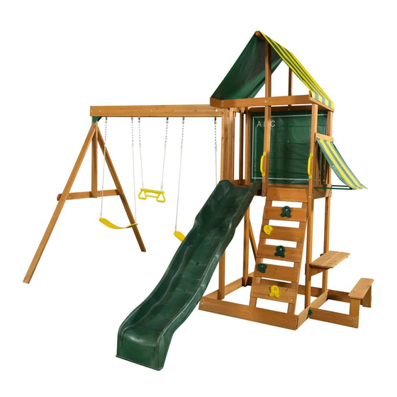
SPRINGFIELD II PLAY SYSTEM - F24017
INSTALLATION AND OPERATING INSTRUCTIONS
26'
25' 1"
13' 1"
10' 2"
8 - 10 Hrs
Two person
assembly
KidKraft, Inc.
4630 Olin Road
Dallas, Texas 75244 USA
customerservice@kidkraft.com
canadacustomerservice@kidkraft.com
1.800.933.0771
972.385.0100
For online parts replacement visit
https://parts.kidkraft.com/
WARNING
and give them to any future owner of this play system. Manufacturer contact information provided below.
OBSTACLE FREE SAFETY ZONE - 26' x 25' 1" area requires Protective Surfacing. See page 3.
MAXIMUM VERTICAL FALL HEIGHT - 6'5"
CAPACITY - 9 Users Maximum, Ages 3 to 10; Weight Limit 110 lbs. (49.9 kg) per child.
RESIDENTIAL HOME USE ONLY. Not intended for public areas such as schools, churches, nurseries, day cares or parks.
Warning. Only for domestic use.
FOR OUTDOOR DOMESTIC USE ONLY
KidKraft Netherlands BV
Olympisch Stadion 8
1076 DE Amsterdam
The Netherlands
europecustomerservice@kidkraft.com
+31 20 305 8620 M-F from 09:00 to 17:30
(GMT+1)
For online parts replacement visit
https://parts.kidkraft.eu/
To reduce the risk of serious injury or death, you must read and
follow these instructions. Keep and refer to these instructions often
Table of Contents
Warnings and Safe Play Instructions . . . . . . . . . . pg . 2
Protective Surfacing Guidelines . . . . . . . . . . . . . . . pg . 3
Instructions for Proper Maintenance . . . . . . . . . pg . 4
About Our Wood - Limited Warranty . . . . . . . pg . 5-6
Keys to Assembly Success . . . . . . . . . . . . . . . . . . . . pg . 7
Part ID . . . . . . . . . . . . . . . . . . . . . . . . . . . . . . . . . . . pg . 8-13
Step-By-Step Instructions . . . . . . . . . . . . . . . . . . .pg . 14
Installation of I . D . / Warning Plaque . . . . . .Last Page
9404017
Rev 09/23/2020
Advertisement
Chapters
Table of Contents

Related Manuals for KidKraft SPRINGFIELD II


Summary of Contents for KidKraft SPRINGFIELD II
-
Page 1: Table Of Contents
SPRINGFIELD II PLAY SYSTEM – F24017 INSTALLATION AND OPERATING INSTRUCTIONS WARNING To reduce the risk of serious injury or death, you must read and follow these instructions. Keep and refer to these instructions often and give them to any future owner of this play system. Manufacturer contact information provided below. -
Page 2: Warnings And Safe Play Instructions
Warnings and Safe Play Instructions CONTINUOUS ADULT SUPERVISION REQUIRED. Most serious injuries and deaths on playground equipment have occurred while children were unsupervised! Our products are designed to meet mandatory and voluntary safety standards. Complying with all warnings and recommendations in these instructions will reduce the risk of serious or fatal injury to children using this play system. -
Page 3: Protective Surfacing Guidelines
Protective Surfacing - Reducing Risk of Serious Head Injury From Falls One of the most important things you can do to reduce the likelihood of serious head injuries is to install shock-absorbing protective surfacing under and around your play equipment. The protective surfacing should be applied to a depth that is suitable for the equipment height in accordance with ASTM F1292. -
Page 4: Instructions For Proper Maintenance
Instructions for Proper Maintenance Your KidKraft Play System is designed and constructed of quality materials with your child’s safety in mind. As with all outdoor products used by children, it will weather and wear. To maximize the enjoyment, safety and life of your Play Set, it is important that you, the owner, properly maintain it. -
Page 5: About Our Wood - Limited Warranty
About Our Wood KidKraft Premium Play Systems uses only premium playset lumber, ensuring the safest product for your children’s use. Although we take great care in selecting the best quality lumber available, wood is still a product of nature and susceptible to weathering which can change the appearance of your set. - Page 6 KidKraft Limited Warranty MISSING OR DAMAGED PARTS: KidKraft will replace any parts within 90 days from date of purchase found to be missing from or damaged in the original packaging. See Fig.1 Fig. 1 Product Age (All Parts) Consumer Pays...
-
Page 7: Keys To Assembly Success
Keys to Assembly Success Tools Required • Tape Measure • #1 Phillips, #2 Robertson • Open End Wrench • 3/16” Hex Key • Carpenters Level and Screwdriver (1/2” & 9/16”) • 8’ Step Ladder • Carpenters Square • Ratchet with extension •... -
Page 8: Part Id
Part Identification (Reduced Part Size) Part Identification (Reduced Part Size) Part Identification (Reduced Part Size) Nominal Size Actual Size 1pc. - 1915 Chalk Wall Spacer (1 x 2 x 29-1/2") - Box 1 - 3641915 1" x 2" ⅝" x 1⅜" 1pc. - Page 9 Part Identification (Reduced Part Size) Part Identification (Reduced Part Size) Part Identification (Reduced Part Size) Nominal Size Actual Size 5pc. - 1776 Floor Board (1 x 6 x 23-1/2") - Box 1 - 3631776 ⅝" x 5⅜" 1" x 6" 1"...
- Page 10 Part Identification (Reduced Part Size) Part Identification (Reduced Part Size) Part Identification (Reduced Part Size) Nominal Size Actual Size 1pc. - 0312 Gusset (2 x 3 x 16") - Box 1 - 3640312 2" x 4" 1⅜" x 3⅜" 2" x 6" 1½"...
- Page 11 Hardware Identification (Actual Size) 1/4 x 3" 1/4 x 1-1/2" 9pc. LS3 - Lag Screw - (9262230) 4pc. LS1 - Lag Screw - (9262212) Hex Bolt 1/4 x 2" 25pc. H2 - - (9277220) Hex Bolt 1/4 x 4" 3pc. H4 - - (9277240) Hex Bolt 1/4 x 4-1/4"...
- Page 12 Hardware Identification (Actual Size) 36pc. TN1 - 1/4" T - Nut (9285200) 30pc. FW3 - #8 Flat Washer - (9251500) 13pc. LW2 - 5/16" Lock Washer - (9253300) 19pc. FW0 - 3/16" Flat Washer - (9251100) 13pc. TN2 - 5/16" T- Nut (9285300) 41pc.
- Page 13 Part Identification (Reduced Part Size) 1X 3320386 Rocks (5pk) 3-Green 2-Yellow 1X 3310148 Slide 48" High Rail -Green 1X 9320374 Big Backyard I.D Plaque w hardware 2X 3724943 1X 3201103 (4pk) 42" Belt Swing Yellow Corner Brace Set w.welded chain 1X 3200184 Triangle Plate (4pk) Green...
- Page 14 Before you discard your cartons fill out the form below. • The carton I.D. stamp is located on the end of each carton. The tracking number is located on the KidKraft ID Plaque (9320374). • Please retain this information for future reference. You will need this information if you contact the Consumer Relations Department.
- Page 15 Step 2: Swing Beam Assembly Warning! For your child’s safety, Fig. 2.4 orientate the swing hangers as shown to ensure your swing will have proper swing motion when installed. Failure to do so could result in premature failure of the swing hanger or swing chain. Make sure triangle is tight against beam B: In the end holes of (1826) Front Beam...
- Page 16 Step 3: Swing End Assembly A: Attach 2 (1863) SW Posts to (1856) SW Upright using 2 (G4) 5/16 x 4” Hex Bolts (with lock washer, flat washer and t-nut). (fig. 3.1) Fig. 3.1 1863 5/16” 1856 T-Nut 5/16” T-Nut 5/16”...
- Page 17 Step 4: Attach Swing End to Swing Beam A: Place (4919) SW Rail Block in the centre between (1826) Front Beam and (1825) Back Beam and attach with 1 (H8) 1/4 x 4-1/4” Hex Bolt (with lock washer, flat washer and t-nut). (fig. 4.1 & 4.2) Fig.
- Page 18 Step 5: Cafe Wall Assembly A: Attach (1914) Cafe Ground with 4 (H2) 1/4 x 2” Hex Bolts (with lock washer, flat washer and t-nut); (1760) Floor using 2 (H2) 1/4 x 2” Hex Bolts (with lock washer, flat washer and t-nut) in the bottom holes, noticing hole locations;...
- Page 19 Step 6: Swing Wall Assembly Part 1 Fig. 6.1 1/4” 1/4” Flat T-Nut Washer A: Attach (1928) Lower Side, noticing the Notice overhang 1/4” Lock at this side side the bolt hole on the extended end is on, Washer using 4 (H2) 1/4 x 2” Hex Bolts (with lock washer, flat washer and t-nut);...
- Page 20 Step 6: Swing Wall Assembly Part 2 5/16” Fig. 6.2 5/16” Flat T-Nut Washer Notice the hole locations of (1861) C: Place (1861) SW Mount across (1924) SW 5/16” Lock SW Mount Washer Floor and (1925) SW Top and attach using 2 (G4) 5/16 x 4”...
- Page 21 Step 7: Fort Frame Assembly A: On the front of the assembly, side without the (0369) Lower Diagonal, attach (1764) Floor Front to both (1500) Posts, noticing the bolt holes are towards the bottom of the board, with 2 (H6) 1/4 x 4-3/4” Hex Bolts (with 1913 Back Floor lock washer, flat washer and t-nut).
- Page 22 Step 8: Attach Lower Back Note: Pre-drill all holes using a 1/8” drill bit before installing the lag screws. A: Attach (1917) Lower Back to the bottom of the (1500) Posts on the back of the assembly with 2 (LS3) 1/4 x 3”...
- Page 23 Step 9: Attach Side Joist A: From inside the assembly attach (1761) Side Joist to (1913) Back Floor with 2 (H2) 1/4 x 2” Hex Bolts (with lock washer, flat washer and t-nut) in the outside holes and 2 (S7) #12 x 2” Pan Screws (with 3/16” flat washer) in the inside holes, as shown in fig.
- Page 24 Step 10: Rock Wall Frame Assembly Part 1 A: Attach (1766) Corner Block to (0349) Rock Rail, flush to the bottom and long side, with 2 (S4) #8 x 3” Wood Screws, as shown in fig. 10.1 and 10.2. Notice which direction the angled edge of (0349) Rock Rail faces. Fig.
-
Page 25: Step 10: Rock Wall Frame Assembly Part
Step 10: Rock Wall Frame Assembly Part 2 B: Place Rock Rail Assembly, from Step 10 Part 1, 5/8” above (1764) Floor Front and tight to (1500) Post on the Cafe Wall Side. (fig. 10.3 and 10.4). Attach (0349) Rock Rail to (1764) Floor Front using 2 (S15) #8 x 1-3/4” Wood Screws as shown in fig. -
Page 26: Fig. 11.1
Step 11: Attach Gusset to Fort A: Make sure the assembly is square before proceeding. B: From the inside of the assembly, attach (0312) Gusset flush to the outside edge of (1500) Post on the Swing Wall using 2 (S4) #8 x 3” Wood Screws. The other end of the gusset should be tight against (1764) Floor Front. (fig. -
Page 27: Wood Parts Hardware
Step 12: Attach Floor Joist to Fort A: From inside of the assembly, measure 3” down from the top of (1760) Floor and (1924) SW Floor then attach (1763) Floor Joist to each board with 1 (S4) #8 x 3” Wood Screw per end. (fig. 12.1, 12.2 and 12.3) Fig. - Page 28 Step 13: Attach Gap and Floor Boards to Fort Part 1 A: Install 1 (1774) CE Gap Board to each end of the assembly attaching to (1761) Side Joist, (1763) Floor Joist and (1764) Floor Front using 5 (S2) #8 x 1-1/2” Wood Screws per board. (fig. 13.1 and 13.2) Fig.
- Page 29 Step 13: Attach Gap and Floor Boards to Fort Part 2 B: In between both (1774) CE Gap Boards place 5 (1776) Floor Boards making sure all boards are evenly spaced. Attach to (1761) Side Joist, (1763) Floor Joist and (1764) Floor Front using 5 (S2) #8 x 1-1/2” Wood Screws per board.
- Page 30 Step 14: Front Wall Frame Assembly A: Attach (1916) Front Divider to (1764) Floor Front with 1 (H6) 1/4 x 4-3/4” Hex Bolt (with lock washer, flat washer and t-nut). Keep bolt loose. (fig 14.1) B: Attach (1927) Top Front Back to (1916) Front Divider with 1 (H4) 1/4 x 4” Hex Bolt (with lock washer, flat washer and t-nut).
- Page 31 Step 15: Attach Rock Rail to Fort A: Place (0349) Rock Rail flush to top of the floor boards and tight to (1916) Front Divider. (fig. 15.1 and 15.2). Attach (0349) Rock Rails to (1764) Floor Front using 2 (S15) #8 x 1-3/4” Wood Screws as shown in fig. 15.3. B: Attach (1767) Lower Front to (0349) Rock Rail with 2 (S2) #8 x 1-1/2”...
- Page 32 Step 16: Rock Wall Assembly A: Attach (1779) CE Access Board flush to the top and outside edges of each (0349) Rock Rail with 4 (S2) #8 x 1-1/2” Wood Screws. (fig. 16.1 and 16.2) B: Below (1779) CE Access Board stagger 3 (1777) CE Rock Board B and 2 (1778) CE Rock Board A, making sure they are evenly spaced with a minimum 2-1/8”...
- Page 33 Step 17: Attach Rocks to Rock Board A: Place 1 rock on each (1777) and (1778) CE Rock Board A & B (fig. 17.1 and 17.2) and attach using 1 (PB2) 1/4 x 1-1/4” Pan Bolt (with lock washer, flat washer and barrel nut) and 1 (S10) #8 x 1” Pan Screw per rock. The rocks can be attached in any order.
- Page 34 Step 18: Attach Ground Stakes MOVE FORT TO FINAL LOCATION. FINAL LOCATION MUST BE LEVEL GROUND Warning! To prevent tipping and avoid potential injury, stakes must be driven 10-1/2” into ground. Digging or driving stakes can be dangerous if you do not check first for underground wiring, cables or gas lines. A: Drive 3 (0318) Ground Stakes 10-1/2” into the ground against (1928) Lower Side at (1500) Post and (0369) Lower Diagonal and against (1914) Cafe Ground at (1500) Post as shown in fig.
- Page 35 Step 19: Back Wall Frame Assembly A: Attach (1912) Back Divider to (1913) Back Floor with 1 (H2) 1/4 x 2” Hex Bolt (with lock washer, flat washer and t-nut). Keep bolt loose. (fig 19.1 and 19.2) B: Attach (1927) Top Front Back to (1912) Back Divider with 1 (H2) 1/4 x 2” Hex Bolt (with lock washer, flat washer and t-nut).
- Page 36 Step 20: Attach Chalk Wall Tarp to Fort A: On the back of the assembly, from the inside, tuck Chalk Wall Tarp between (1927) Top Front Back and both (1500) Posts and between (1913) Back Floor and both (1500) Posts. (fig. 20.1) B: Make sure Chalk Wall Tarp is smooth and tight then attach to the outside of each (1500) Post, 1/2”...
- Page 37 Step 21: Swing Side Wall Assembly A: In between both (1500) Posts on Swing Wall side, measure 3/4” up from (1774) CE Gap Board and attach 2 (0304) CE Floor Boards to (1924) SW Floor and (1925) SW Top using 4 (S1) #8 x 1-1/8” Wood Screws per board. (fig.
- Page 38 Step 22: Cafe Wall Assembly A: In between both (1500) Posts on Cafe Wall side, measure 3/4” up from (1774) CE Gap Board and attach 3 (0304) CE Floor Boards to (1760) Floor and (1923) Side Top using 4 (S1) #8 x 1-1/8” Wood Screws per board. The distance between boards should be evenly spaced, not exceeding 2-1/2”.
- Page 39 Step 23: Roof Frame Assembly A: Pre-drill pilot holes for the screws using a 1/8” drill bit, centred on the end of each (1927) Top Front Back, then attach (1918) Roof End to each (1927) Top Front Back with 4 (S2) #8 x 1-1/2” Wood Screws. Make sure the edge of (1918) Roof End is flush to the outside edge of (1927) Top Front Back on the back side of the assembly.
- Page 40 Step 24: Attach Canopy to Roof Frame A: Place Springfield Canopy over (1919) Roof Ridge making sure bottom edges of tarp are even on both sides of assembly. (fig. 24.1) B: Secure one side by attaching canopy to (1925) SW Top using 5 evenly spaced (S5) #8 x 1/2” Pan Screws (with #8 flat washer).
- Page 41 Step 25: Cafe Table Assembly Part 1 Note: Pre-drill all holes using a 1/8” drill bit before installing the lag screws. A: Attach 1 (1926) Table Support to the inside of each (1500) Post on the Cafe Wall side through the middle hole using 1 (LS3) 1/4 x 3”...
- Page 42 Step 25: Cafe Table Assembly Part 2 C: Attach 1 (1911) Table Top to the top of (1926) Table Supports, tight to (1500) Posts, using 4 (S2) #8 x 1-1/2” Wood Screws, as shown in fig. 25.5. D: Tight to the first (1911) Table Top attach a second one with 2 (S2) #8 x 1-1/2” Wood Screws in the inside holes and 2 (S1) #8 x 1-1/8”...
- Page 43 Step 26: Seat Assembly A: Attach (1922) Seat Rail flush to the top and outside edges of 2 (1921) Seat Post with 4 (S2) #8 x 1-1/2” Wood Screws as shown in fig. 26.1. Notice the bolt holes in (1921) Seat Posts are at the bottom of the boards. B: Centre (1910) Seat on top of (1921) Seat Posts and attach with 4 (S2) #8 x 1-1/2”...
- Page 44 Step 27: Attach Seat Assembly to Fort A: With (1922) Seat Rail facing the fort, attach (1917) Lower Back to (1921) Seat Post using 2 (H2) 1/4 x 2” Hex Bolts (with lock washer, flat washer and t-nut). (fig. 27.1 and 27.2) B: On the other side of the Seat Assembly attach (1920) Seat Bottom to (1921) Seat Post with 2 (H2) 1/4 x 2”...
- Page 45 Step 28: Attach Slide to Fort Note: Pre-drill all holes using a 1/8” drill bit before installing the pan screws. A: Place Slide in the centre between (1916) Front Divider and (1500) Post. (fig. 28.1 and 28.2) B: Attach slide to fort through the floor boards and into (1764) Floor Front using 3 (S7) #12 x 2” Pan Screws. (fig.
- Page 46 Step 29: Attach Swing Assembly to Fort A: Attach Swing Assembly from Step 4 to (1861) SW Mount with 1 (G5) 5/16 x 4-1/2” Hex Bolt (with lock washer, flat washer and t-nut) and 1 (G8) 5/16 x 2” Hex Bolt (with 2 flat washers and 1 lock nut) as shown in fig.
- Page 47 Step 30: Attach Swing Ground Stakes A: Drive 1 (0318) Ground Stake 10-1/2” into the ground at each (1863) SW Post and attach with 2 (S3) #8 x 2-1/2” Wood Screws per ground stake. (fig. 30.1 and 30.2) Warning! To prevent tipping and avoid potential injury, stakes must be driven 10-1/2”...
- Page 48 Step 32: Attach Glider and Swings If Bolt protrudes Warning! beyond T-Nut Check entire play centre for bolts protruding beyond T-Nuts. Use Use an extra extra washers to eliminate this condition. Flat Washer A: Attach 1 Acro Swing to the Bolt-Thru Swing Hangers. (fig. 31.1) B: Attach 2 Belt Swings to the Bolt-Thru Swing Hangers.
- Page 49 Hardware Other Parts #8 x 1/2” Pan Screw 1 x KidKraft I.D. Plaque...
- Page 50 NOTES...
- Page 51 NOTES...
- Page 52 Would you recommend the purchase of our products to friends and family? Comments: MAIL TO: Fill out your registration card online at KidKraft https://prdregistration.kidkraft.com/ 4630 Olin Road Dallas, TX 75244 United States KidKraft would like to say Thank You for Attention: Customer Service your time and feedback.
Need help?
Do you have a question about the SPRINGFIELD II and is the answer not in the manual?
Questions and answers
How long does this take to assemble?