Advertisement
Quick Links
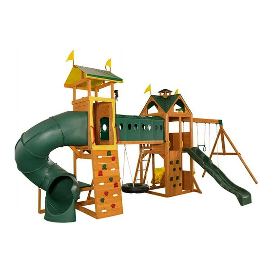
Mockingbird View Swing Set and Activity Center - F24848
INSTALLATION AND OPERATING INSTRUCTIONS
Mockingbird View Safety Zone
Mockingbird View Safety Zone
36'-1"
37'-3"
37'-3"
24'-1"
24'- 1"
24'- 1"
KidKraft, Inc.
4630 Olin Road
Dallas, Texas 75244 USA
customerservice@kidkraft.com
canadacustomerservice@kidkraft.com
1.800.933.0771
972.385.0100
For online parts replacement visit
https://parts.kidkraft.com/
WARNING
any future owner of this play system. Manufacturer contact information provided below.
OBSTACLE FREE SAFETY ZONE - 36'-1" x 27' area requires Protective Surfacing. See Page 3
MAXIMUM VERTICAL FALL HEIGHT - 6'9"(2.06m)
- 17
Users Maximum, Ages 3 to 10; Weight Limit 110 lbs. (49.9 kg) per child.
CAPACITY
27'
27'-11"
11'-5"
RESIDENTIAL HOME USE ONLY. Not intended for public areas such as schools, churches,
11'-4"
nurseries, day cares or parks.
27'-11"
11'-4"
Warning. Only for domestic use.
KidKraft Netherlands BV
Olympisch Stadion 29
1076DE Amsterdam
The Netherlands
europecustomerservice@kidkraft.com
+31 20 305 8620 M-F from 09:00 to 17:30
(GMT+1)
For online parts replacement visit
https://parts.kidkraft.eu/
To reduce the risk of serious injury or death, you
must read and follow these instructions. Keep and
refer to these instructions often and give them to
Table of Contents
Warnings and Safe Play Instructions . . . . . . . . . . pg . 2
Protective Surfacing Guidelines . . . . . . . . . . . . . . . pg . 3
Instructions for Proper Maintenance . . . . . . . . . pg . 4
About Our Wood - Limited Warranty . . . . . . . . . pg . 5
Keys to Assembly Success . . . . . . . . . . . . . . . . . . . . pg . 6
Part ID . . . . . . . . . . . . . . . . . . . . . . . . . . . . . . . . . . . pg . 8-23
Step-By-Step Instructions . . . . . . . . . . . . . . pg . 24-130
Installation of I . D . / Warning Plaque . . . . . .Final Step
9404848
18 - 26 Hrs
TWO PERSON
ASSEMBLY
Rev 06/21/2019
Advertisement

Related Manuals for KidKraft F24848


Summary of Contents for KidKraft F24848
-
Page 1: Table Of Contents
Mockingbird View Swing Set and Activity Center – F24848 INSTALLATION AND OPERATING INSTRUCTIONS Mockingbird View Safety Zone WARNING Mockingbird View Safety Zone To reduce the risk of serious injury or death, you must read and follow these instructions. Keep and 36'-1"... -
Page 2: Warnings And Safe Play Instructions
Warnings and Safe Play Instructions CONTINUOUS ADULT SUPERVISION REQUIRED. Most serious injuries and deaths on playground equipment have occurred while children were unsupervised! Our products are designed to meet mandatory and voluntary safety standards. Complying with all warnings and recommendations in these instructions will reduce the risk of serious or fatal injury to children using this play system. -
Page 3: Protective Surfacing Guidelines
Protective Surfacing - Reducing Risk of Serious Head Injury From Falls One of the most important things you can do to reduce the likelihood of serious head injuries is to install shock-absorbing protective surfacing under and around your play equipment. The protective surfacing should be applied to a depth that is suitable for the equipment height in accordance with ASTM F1292. -
Page 4: Instructions For Proper Maintenance
Instructions for Proper Maintenance Your KidKraft Play System is designed and constructed of quality materials with your child’s safety in mind. As with all outdoor products used by children, it will weather and wear. To maximize the enjoyment, safety and life of your Play Set, it is important that you, the owner, properly maintain it. -
Page 5: About Our Wood - Limited Warranty
About Our Wood KidKraft Premium Play Systems uses 100% FSC wood. Although we take great care in selecting the best quality lumber available, wood is still a product of nature and susceptible to weathering which can change the appearance of your set. -
Page 6: Keys To Assembly Success
Keys to Assembly Success Tools Required • Tape • Tape Measure • #1, #3 Phillips or Robertson • Open End Wrench • 3/16” Hex Key • Carpenter’s Level bit or Screwdriver (1/2” & 7/16”) • 8’ Step Ladder • Carpenter’s Square •... -
Page 8: Part Id
Lookout Tower and Swing Part Identification (Reduced Part Size) Part Identification (Reduced Part Size) Part Identification (Reduced Part Size) Part Identification (Reduced Part Size) 4pc. - 2850 - 31.8 x 76.2 x 304.8mm - Tower Gusset 3pc. - 1578 - 28.6 x 403.2mm - Dowel -Tennon 3632850 3681578 - Box 1 -... - Page 9 Lookout Tower and Swing Part Identification (Reduced Part Size) Part Identification (Reduced Part Size) Part Identification (Reduced Part Size) Part Identification (Reduced Part Size) 3632616 1pc. - 2616 - 23.8 x 82.6 x 1181.1mm - SW Support - Box 1 - 3632851 4pc.
- Page 10 Lookout Tower and Swing Part Identification (Reduced Part Size) Part Identification (Reduced Part Size) Part Identification (Reduced Part Size) Part Identification (Reduced Part Size) 1pc. - 2627 - 31.8 x 1066.8 x 2209.8 mm - SW Wall Panel - Box 1 - 37632627...
- Page 11 Lookout Tower and Swing Hardware Identification (Actual Size) 5pc. LW2 28pc. TN1 - 1/4" T - Nut (54303200) 42pc. FW1 8pc. FW0 5/16" Lock Washer 1/4" Flat Washer 3/16" Flat Washer (51303300) (51103200) (51103100) 36pc. LW1 54pc. FW2 - 5/16" Flat Washer - (51103300) 1/4"...
- Page 12 Lookout Tower and Swing Part Identification (Reduced Part Size) 1x - Slide 48" High Rail (3310149) 1x - Rebar Ground 1x - Kidkraft Stake (6 Pk) ID Plaque (3200318) (9320374) 2x - Rocks (4 Pk) (3320184) -Green 2x - Acro Handle...
- Page 13 Adventure Tower Part Identification (Reduced Part Size) Part Identification (Reduced Part Size) Part Identification (Reduced Part Size) Part Identification (Reduced Part Size) 3638834 2pc. - 8834 - 23.8 x 82.6 x 216mm - Box Gusset FSC - Box 1 - 3636005 1pc.
- Page 14 Adventure Tower Part Identification (Reduced Part Size) Part Identification (Reduced Part Size) Part Identification (Reduced Part Size) Part Identification (Reduced Part Size) 1pc. - 6019 - 15.9 x 133.4 x 596.9mm Rock Bottom - 4pc. - 6010 - 15.9 x 133.4 x 596.9mm Rock Board A - 3636019 3636010 Box 1 -...
- Page 15 Adventure Tower Part Identification (Reduced Part Size) Part Identification (Reduced Part Size) Part Identification (Reduced Part Size) Part Identification (Reduced Part Size) 3636031 4pc. - 6031 - 15.9 x 72.6 x 996.9mm Window Brace - Box 1 - 3636007 2pc. - 6007 - 31.8 x 76.2 x 1095.4mm Wall Support - Box 1 - 3636020 1pc.
- Page 16 Adventure Tower Hardware Identification (Actual Size) 12pc. FW3 - #8 Flat Washer - (51003500) 13pc. FW0 - 3/16" Flat Washer - (51103100) 39pc. TN1 - 1/4" T - Nut (54503200) 48pc. LW1 - 1/4" Lock Washer - (51303200) 52pc. FW1 - 1/4" Flat Washer - (51103200) 9pc.
- Page 17 6’ Tunnel & Tire Swing Part Identification (Reduced Part Size) Part Identification (Reduced Part Size) Part Identification (Reduced Part Size) Part Identification (Reduced Part Size) 2pc. - 6040 - 31.8 x 82.6 x 367mm Tunnel End - Box 1 - 3636040 3639087 1pc.
- Page 18 6’ Tunnel & Tire Swing Hardware Identification (Actual Size) 8pc. FW1 - 1/4" Flat Washer - (51103200) 4pc. TN2 - 5/16" T- Nut (54503300) 4pc. LW2 - 5/16" Lock Washer - (51303300) #12 Lock Nut 24pc. LN4 - - (54303600) 4pc.
- Page 19 6’ Tunnel & Tire Swing Part Identification (Reduced Part Size) 2x - Flat Panel Brkt (2 Pk) 3200636 2x - MOD Tunnel Set (4Pk) (3330101) 1x - Swing Brkt Set (4 Pk) (3201532) 1x - Swing Brkt Set (2 Pk) (3201533) 1x - Tire Rope &...
- Page 20 Activity & Roof Add On Part Identification (Reduced Part Size) Part Identification (Reduced Part Size) 3632839 1pc. - 2839 - 12.7 x 57.2 x 428.6mm - Bottom - Box 1 - 3632837 2pc. - 2837 - 25.4 x 57.2 x 355.6mm - Diagonal - Box 1 - 3632838 2pc.
- Page 21 Activity & Roof Add On Hardware Identification (Actual Size) 2pc. FW1 1/4" Flat Washer (51103200) #8 x 1" 8pc. S33 - Wood Screw - (52043510) #8 x 1-1/2" 104pc. S2 - Wood Screw - (52043512) #8 x 2" 28pc. S11 - Wood Screw - (52043522) #8 x 2-1/2"...
- Page 22 Activity & Roof Add On Part Identification (Reduced Part Size) Part Identification (Reduced Part Size) Part Identification (Reduced Part Size) Part Identification (Reduced Part Size) - Basketball Backboard with Pinch Guard (3330740) - Hoop Net and Ball - Telescope w Mount (3330052) (3320161) - Toss Game Add-On...
- Page 23 Twist-N-Ride 4 Slide (3310130) 10x - TNR 4 Clamp Ring (9300130) (Green) 10pcs number 3300130 (93201 (3310132) Green (3310131) Green (33101 (9283200) (3310121) Green 1x - Rebar Ground Stake (9200318) 7608935 3638934 4638965 4638963...
- Page 24 Before you discard your cartons fill out the form below. • The carton I.D. stamp is located on the end of each carton.The tracking number is located on the KidKraft ID Plaque (9320374). • Please retain this information for future reference. You will need this information if you contact the Consumer Relations Department.
- Page 25 Lookout Tower & Swing Step 2: Front and Back Wall Prep Part 1 It is important to assemble the frame on a flat, smooth surface. A: Place (2771) End Post and (2770) End Post Left side by side with the grooves facing up and in. Put (2770) End Post Left on the right hand side.
- Page 26 Step 2: Front and Back Wall Prep Part 2 It is important to assemble the frame on a flat, smooth surface. D: Turn the assembly over, place (2774) Upright in the middle grooves of (2775) Panel Cross Support and (2772) Panel Floor Support then attach all boards with 8 (H9) Hex Bolts (with lock washer and flat washer) connecting to the previously installed t-nuts.
- Page 27 Step 3: End Wall Prep Part 1 It is important to assemble the frame on a flat, smooth surface. A: Place (2768) Panel Floor and 2 (2769) Panel BT Frames on a hard, flat surface with the long side up. Tap in 2 (TN1) T-nuts per board.
- Page 28 Step 3: End Wall Prep Part 2 It is important to assemble the frame on a flat, smooth surface. D: Turn the assembly over then attach all boards with 6 (H9) 1/4 x 1-1/4” Hex Bolts (with lock washer and flat washer) connecting to the previously installed t-nuts.
- Page 29 Step 4: Frame Assembly Part 1 It is important to assemble the frame on a flat, smooth surface. A: Place (2627) SW Wall Panel between 2 Front and Back Walls from Step 2, noticing the wall orientations. The tops and bottoms of the walls should be flush. Make sure the walls are square then using the pilot holes as a guide pre-drill with a 3/16”...
- Page 30 Step 4: Frame Assembly Part 2 B: Place End Wall from Step 3 between the Front Wall and Back Wall noticing the wall orientation. The tops and bottoms of the walls should be flush. Make sure the walls are square then using the pilot holes as a guide predrill with a 3/16”...
- Page 31 Step 4: Frame Assembly Part 3 C: Loosely attach 1 (2607) Diagonal to (2606) SW Ground with 1 (H10) 1/4 x 2-1/4” Hex Bolt (with lock washer, flat washer and t-nut). (fig.4.6) D: Place (2606) SW Ground against the front right side of the (2627) SW Wall Panel making sure that the (2607) Diagonal lines up with the edge of the panel as shown in fig.
- Page 32 Step 5: Floor Assembly Part 1 A: From inside of the assembly centre (2608) Floor Joist over the pilot holes in both (2768) Panel Floors in the Swing and End Walls, measure 5/8” (15.9 mm) down from the top of boards then attach (2608) Floor Joist to each board using the left and centre holes with 2 (S4) #8 x 3”...
- Page 33 Step 5: Floor Assembly Part 2 B: On the inside of both the Front and Back Walls loosely attach 1 (2610) Side Joist to each (2772) Panel Floor Support with 2 (H11) 1/4 x 2-3/4” Hex Bolts (with lock washer, flat washer and t-nut) as shown in fig. 5.5. Make sure both (2610) Side Joist are level with (2608) Floor Joist.
- Page 34 Step 5: Floor Assembly Part 3 C: Fasten each (2610) Side Joist to each (2772) Panel Floor Support with 4 (S3) #8 x 2-1/2” Wood Screws per board as shown in fig. 5.6. D: Tighten all (H11) 1/4 x 2-3/4” Hex Bolts in both (2610) Side Joist. Fig.
- Page 35 Step 5: Floor Assembly Part 4 E: Starting at (2627) SW Wall Panel place (2648) Floor Board followed by 8 (2609) Floor Boards. Make sure all boards are evenly spaced then attach to (2608) Floor Joist and each (2610) Side Joist with 5 (S2) #8 x 1-1/2” Wood Screws per board.
- Page 36 Step 6: Swing Beam Assembly A: Attach 6 Swing Hangers to the (2614) Engineered Beam using 2 (G7) Hex Bolts (with 2 flat washers and 1 lock nut) per Swing Hanger as shown in fig. 6.1. B: Flush to the Fort End of (2614) Engineered Beam attach 2 L-Beam Brackets with 2 (G21) Hex Bolts (with 2 flat washers and 1 lock nut).
- Page 37 Step 7: Swing End Assembly A: Loosely attach 2 (2613) Heavy SW Posts to (2615) SW Upright using 2 (G7) 5/16 x 5-1/2” Hex Bolts (with lock washer, flat washer and t-nut). Notice 2 bolt holes at top of (2615) SW Upright and orientation of angle. (fig.
- Page 38 Step 8: Attach Swing End to Swing Beam A: Place Swing End Assembly against Swing Beam Assembly then place 1 Beam Bracket on each side of the assembly (they are specific for left and right side) and attach with 5 (G21) 5/16 x 3-3/4” Hex Bolts (with 2 flat washers and 1 lock nut).
- Page 39 Step 9: Attach Swing Assembly To Fort A: Place Swing Assembly against top of (2627) SW Wall Panel, make sure assembly is level then attach from inside the fort assembly into each L-Beam Bracket with 4 (G27) 5/16 x 1 ¾” Hex Bolts (with 2 flat washers and 1 lock nut).
- Page 40 Step 10: Install Ground Stakes MOVE FORT TO FINAL LOCATION PRIOR TO STAKING FINAL LOCATION MUST BE LEVEL GROUND A: In the 5 places shown in (fig.10.1) drive the Rebar Ground Stakes 13” (330mm) into the ground against outside front corner of End Wall Assembly, on both (2607) Diagonals and both (2613) Heavy SW Posts. Be careful not to hit the washer while hammering stakes into the ground as this could cause the washer to break off.
- Page 41 Step 11: Install Upper and Lower Jambs A: In the upper opening of End Wall Assembly place 1 (2602) Upper Jamb so it measures 17”(432mm) to the inside of each post then attach with 2 Jamb Mounts using 4 (S0) #8 x 7/8” Truss Screws per mount. (fig. 11.1 &11.2 &...
- Page 42 Step 12: Install Tower Gussets A: On the Back Wall, place 2 (2850) Tower Gussets so they are flat against the (2772) Panel Floor Support and to the insides of the (2771) End Post and (2770) End Post Left. Attach using 1 (S11) #8 x 2” Wood Screw Wood and 1 (S4) #8 x 3”...
- Page 43 Step 13: Access Ladder Assembly Part 1 ATTENTION: IMPORTANT INFORMATION ABOUT YOUR ASSEMBLY All holes for the dowel assemblies MUST be pre-drilled using a 1/8” drill bit. Failure to pre-drill can result in splitting and/or cracking of the wood pieces. A 1/8”...
- Page 44 Step 13: Access Ladder Assembly Part 2 D: On the Back Wall of the assembly and to the right, place Ladder Assembly against (2618) as shown in fig. 13.5 making sure that it is flush. Pre-drill holes with a 1/8”(3.2mm) drill bit then attach using 2 (LS3) 1/4 x 3” Lag Bolt (with flat washer).
- Page 45 Step 13: Access Ladder Assembly Part 3 E: On the inside bottom of (2846) Ladder Rail Right attach 1 (9195) Ladder Brace using 2 (S11) #8 x 2” Wood Screws keeping it flush to (2769) Panel BT Frame. (fig. 13.7 and 13.8) F: From inside the Fort measure approximately 3”...
- Page 46 Step 14: Vertical Wall Assembly Part 1 4X Vert Rock Board (note orientation, every other A: On the lower left hand side of the Front Wall place 4 (2851) Vertical Rock Boards tight together making sure board is flipped) that they are centered in the opening and flush to the top. It is important to note hole orientation, every other 16X #8 x 1-1/2"...
- Page 47 Step 14: Vertical Wall Assembly Part 2 C: Alternating shapes, attach 2 rocks to each (2851) Vertical Rock Board using 1 (PB2) ¼ x 1-1/4” Pan Bolt (with ¼” lock washer, 3/16” flat washer and ¼” barrel nut) and 1 (S10) #8 x 1” Pan Screw per rock. The Pan Screw is placed in the hole beneath the Pan Bolt.
- Page 48 Step 15: Attach Hand Grips A: On the (2770) End Post Left measure 2”(50.8mm) up from the top of the Vertical Rock Boards and center 1 Hand Grip on the post. Pre-drill with a 1/8”(3.2mm) drill bit and attach using 2 (LS1) ¼ x 1-1/2” Lag Screw (with flat washers).
- Page 49 Step 16: Attach Slide to Fort A: Place Slide in the center of the opening on the front right of the fort as shown in fig. 16.1, pre-drill with a 1/8” (3.2 mm) drill bit then attach slide to fort through the (2772) Panel Floor Support using 3 (S7) #12 x 2” Pan Screws.
- Page 50 Step 17: Lower Jamb Assembly A: In the lower opening of the Back Panel place 1 (2601) Lower Jamb so it measures 17” (432mm) to the inside of each post then attach (2601) Lower Jamb with 2 Jamb Mounts using 4 (S0) #8 x 7/8” Truss Screws per mount. (fig.
- Page 51 Step 18: Banister Assembly A: From inside the fort on the top right hand side of the End Wall measure 3”(76.2mm) up from the top of the floor boards. Attach 1 (2844) Horizontal using 4 (S2) #8 x 1-1/2” Wood Screws. (fig. 18.1 and 18.2) B: Measure 15”(381mm) up from the top of the (2844) Horizontal installed in Step A and install a second (2844) Horizontal using 4 (S2) #8 x 1-1/2”...
- Page 52 Activity & Roof Add On Step 19: Gable End Assembly Part 1 A: Attach one (2852) Roof End to a second (2852) Roof End at peak using 1 (S3) #8 x 2-1/2” Wood Screw. (Fig. 19.1) B: Place 1 (2853) Roof Support between the Roof Ends so the bottom of the Roof Support is flush with the bottoms of each Roof End.
- Page 53 Step 19: Gable End Assembly Part 2 D: From the peak of the gable assembly measure approximately 3” (80.37mm) down and attach 1 (2843) Gable Board C using 4 (S2) #8 x 1-1/2” Wood Screws as shown in (fig. 52.3 and 52.4). There should be maintaining a 1”...
- Page 54 Step 20: Attach Gables to Fort flush A: Center 1 Gable Assembly on the top of each wall panel as shown in fig. 20.2 making sure that the assemblies are flush with the front of the wall panels. Attach each Gable Assembly to the panel using 4 (S4) #8 x 3” Wood 4X #8 x 3"...
- Page 55 Step 21: Attach Roof Panels Part 1 Note: It is important to ensure that there is a 5mm square opening in the top, center of the roof. This will be used in a later step. Build 4 of these assemblies Build 4 of these assemblies A: Bend roof panel along the fold to allow the panel to fit between the gables.
- Page 56 **other gables hidden for clarity** 2X #8 x 1-1/2" WS per roof Step 21: Attach Roof Panels Begin with two gable assemblies and assemble Part 2 as shown note: this hole D: Take a second roof panel and fit the connector tabs so they are coupled with the panel that was previously **other gables hidden for clarity** 2X #8 x 1-1/2"...
- Page 57 Step 21: Attach Roof Panels Part 3 E: Repeat all steps to complete the roof assembly, making sure that a 5mm square opening is left in the center of the roof assembly. (fig. 21.9, 21.10 and 21.11) Fig. 21.9 continue with the other 3 assemblies leaving a 5mm square opening in the centre...
- Page 58 Step 22: Cupola Assembly Part 1 A: Place Weather Vane Base onto Roof Mount so that the holes line up as shown in fig. 22.1. Attach using 2 (S37) #7 x 5/8” Pan Screw. B: Slide each (2940) Cupola Roof section between Base and Roof Mount. Tape sections together in 4 places as shown in fig.
- Page 59 Step 22: Cupola Assembly Part 2 D: Place 1 (2936A) Bell Cupola Side on each side of 1 (2938) Cupola Side Base with the open side of the Cupola Side Base facing the bottom. Make sure that the Cupola Posts and Cupola Side Base are flush at the bottom and attach using 4 (TS) #6 x 30mm Trim Screws.
- Page 60 Step 22: Cupola Assembly Part 3 A: Place Steel Cupola Mount over the Bell. From inside the Bell push the Bell Clapper with screw upwards so that it is going through the Bell and the center hole on the Cupola Mount. Install the Bell Nut to secure into place. (fig.
- Page 61 Step 23: Attach Cupola Part 1 A: Place 2 (2939) Mount Blocks (fig. 23.3 and 23.4) over the top of the roof so that the holes lines up with the starter holes in the panel. Attach using 4 (S2) #8 x 1-1/2 Wood Screws. (fig. 23.1, 23.2, 23.3 and 23.4) screw holes in mount block 2939 line up to starter holes in roof...
- Page 62 Step 23: Attach Cupola Part 2 B: Place Cupola Assembly over both Mount Blocks and attach as shown in fig. 23.5 using 4 (TS) #6 x 30mm Trim Screws. C: Pull string for bell through the square hole in the roof assembly. (fig. 23.6) Cupola Assembly Fig.
- Page 63 Step 24: Attach Telescope A: On the front panel center the telescope on the (2853) Roof Support and attach using 2 (S2) #8 x 1-1/2” Wood Screws. (Fig. 24.1 and fig. 24.2) Fig. 24.1 Telescope 1-3/4" WS 2853 2X #8 x 1-3/4" WS Telescope Fig.
- Page 64 Step 25: Attach Flags A: On the Swing Wall panel and the End Wall Panel attach 1 Flag per side at the top corners of the Gable Assembly using 2 (S10) #8 x 1” Pan Screws per flag. (Fig. 25.2) 2X #8 x 1-3/4"...
- Page 65 Step 26: Install Basketball Net Part 1 A: Hold Hoop against the front of the Backboard and place the Backplate behind as shown in fig. 26.1. Insert the supplied 3 Carriage Bolts and Lock Nuts through the Hoop, Backboard and Backplate and attach. (fig. 26.1 and 26.3) B: Loop the Net around Hoop clips.
- Page 66 Locations Step 26: Install Basketball Net Part 2 C: In the location shown in (Fig.26.4), measure 3.25” (82.6mm) up from the floor and install Backboard to Fort using 8 (S33) #8 x 1” Wood Screws. (Fig. 26.3, 26.4 and 26.5) Fig.
- Page 67 Step 26: Install Basketball Net Part 3 D: From inside the fort place 1 (2844) Horizontal behind the Backboard as shown in fig. 26.6 and attach to (2771) Post and (2774) Upright using 4 (S2) #8 x 1-1/2” Wood Screws. (fig. 26.6) Inside View Fig.
- Page 68 Step 27: Assemble Bean Bag Toss Part 1 A: Place 1 (2838) Leg flush to 1 (2837) Diagonal as shown, note the board orientation. Pre-drill holes in (2838) Leg using a 1/8” (3.2mm) drill bit and attach (2837) Diagonal using 2 (S4) #8 x 3” Wood Screws. Repeat step to make a second assembly.
- Page 69 Step 27: Assemble Bean Bag Toss Part 2 C: Place 1 (2839) Bottom so that it’s centered across the inside of the (2838) Legs. Attach using 2 (S2) #8 x 1-1/2” Wood Screws per side. Fig. 27.3 2839 2838 Hardware Wood Parts #8 x 1-1/2”...
- Page 70 Step 27: Assemble Bean Bag Toss Part 3 D: Place Bean Bag Toss so that the top section will attach from inside the Fort and the bottom section fits over the leg assemblies. Attach top section from the inside using 4 (S10)#8 x1” Pan Screws and bottom section from the outside using 4 (S10) #8 x 1”...
- Page 71 Adventure Tower Assembly Step 28: Upper Frame Assembly A: Place 1 (6012) Short Post and 1 (6000) Upper Post side by side with the (6012) Short Post on the left side making sure that the notched out end is at the bottom and facing the outside. Place (6023) Roof Side at the top of the posts so that it’s flush and attach using 2 (H2) ¼...
- Page 72 Step 29: Lower Frame Assembly Part 1 A: Place 1 (6002) Long Post and 1 (6026) Rock Rail side by side with the (6002) Long Post on the left side making sure that the notched out end is at the top and on the inside. It is important to ensure that the angled cut on the (6026) Rock Rail is at the top, facing inwards towards the (6002) Long Post.
- Page 73 Step 29: Lower Frame Assembly Part 2 C: Place 1 (6002) Long Post and 1 (6026) Rock Rail side by side with the (6002) Long Post on the right side, notched end at the top and facing the inside and the (6026) Rock Rail on the left. Make sure that the angled cut on the (6026) Rock Rail is at the top, facing inwards towards the (6002) Long Post.
- Page 74 Step 30: Frame Assembly A: Make sure that lower frame assemblies are square then attach 1 (6021) Back Ground to the outside of the (6002) Long Posts using 4 (S11) #8 x 2” Screws (with 3/16” flat washer) making sure that it is flush to the bottom. (Fig. 30.3 & 30.4 ) B: Making sure that it’s flush to the bottom of the (6020) Short Ground and (6018) Long Ground, attach 1 (6019) Rock Bottom to the Rock Rails using 4 (S20) #8 x 1-3/8”...
- Page 75 Step 31: Floor Assembly A: Place (6003) Floor Joist flush to the underside of the (6013) Floor Board and centred over the pilot holes in the (6034) Floor Back and (0600) Bottom Trim. The angle cut should be flush with the (0600) Bottom trim (Fig.
- Page 76 Step 32: Climbing Wall Assembly A: Starting with a (6009) Rock Board B at both the top and bottom of the Climbing Wall, alternate between (6010) Rock Boards A and (6009) Rock Boards B making sure that the boards are evenly spaced as shown in (fig. 32.1). Attach using 4 (S20) #8 x 1-3/8”...
- Page 77 Step 33: Wall Top Assembly Part 1 A: Making sure that assemblies are square, position the Left Wall Assembly onto the lower left assembly as shown in (fig. 33.1 & 33.2). Attach (6002) Long Post to (6012) Short Post using 1 (H12) 1/4 x 3” Hex Bolt (with lock washer, flat washer and t-nut).
- Page 78 Step 33: Wall Top Assembly Part 2 B: Repeat step A to install the Right Wall Assembly. (fig. 33.3 & 33.4) Before proceeding to the next step ensure Fig. 33.4 that unit is completely Fig. 33.3 square and all hardware is tightened. 6012 6000 flat...
- Page 79 Step 34: Install Top Back A: On the back side of the assembly install (6028) Top Back using 2 (H8) ¼ x 4-1/4” Hex Bolt (with flat washer, lock washer and t-nut) in the upper hole and 2 (S7) #12 x 2” Pan Screws in the bottom holes. (fig 34.1 & 34.3) B: On the left and right Roof Sides install 2 (S20) #8 x 1-3/8”...
- Page 80 Step 35: Install Gussets Part 1 A: On the back side of the assembly place 2 (6006) Back Gussets so they meet tightly together to form a point. Center the (6006) Back Gussets on the inside of the (6034) Floor Back making sure the other ends are flush to the Long Posts.
- Page 81 Step 35: Install Gussets Part 2 C: On the right side of the assembly place 2 (6001) Gussets so that they are flush to the (6017) Floor Support. The upper corner of the front (6001) Gusset should be flush to back of the wall boards while the other (6001) Gusset should butt up against the (6006) Back Gusset previously installed.
- Page 82 Step 36: Attach Tarp Frame Part 1 A: Place 1 (6024) Tarp End on either side of the (6023) Roof Sides as shown in (Fig. 36.1 & 36.2). Pre-drill with a 1/8” (3.2mm) drill bit and attach from the outside using 4 (S20) #8 x 1-3/8” Wood Screws per side. B: On each inside corner attach a Corner Bracket to the (6024) Tarp Ends and (6023) Roof Sides using 3 (S37) #7 x 5/8”...
- Page 83 Step 36: Attach Tarp Frame Part 2 C: From inside the assembly using the center holes on the (6023) Roof Sides attach 1 (6008) Tarp Upright per side with 1 (H2) ¼ x 2”Hex Bolt (with flat washer, lock washer and t-nut) per side in the upper holes and 1 (S15) #8 x 1-3/4”...
- Page 84 Tower Canopy 889 x 117.6mm Step 37: Attach Tower Canopy A: Place Tower Canopy over (6025) Tarp Support making sure bottom edges of Tower Canopy are even on both sides of assembly.(Fig. 37.1) B: Secure one side by attaching Tower Canopy to 1 (6024) Tarp End using 5 (S37) #7 x 5/8” Pan Screws (with #8 flat washer).
- Page 85 Step 38: Install Flags A: On each end of the (6025) Tarp Support center 1 Flag and attach using 2 (S10) #8 x 1” Pan Screws per side. (Fig. 38.1 &38. 2) flag Fig. 38.1 Fig. 38.2 center in end of Tarp Support center in end of Tarp Support...
- Page 86 Step 39: Attach Trim A: Flush to the (0600) Bottom Trim and to the outside edge of the (6026) Rock Rail attach 1 (0602) Short Trim on each side of the (6026) Rock Rails with 1 (S20) #8 x 1-3/8” Wood Screw per side in the center hole. (Fig. 39.1 & 39.2) B: Flush to the top of both (0602) Short Trims attach 1 (0601) Side Trim with 4 (S20) #8 x 1-3/8”...
- Page 87 Step 40: Attach Hand Grips A: Place 1 Hand Grip over the existing holes in (0602) Short Side Trim, making sure that it’s centered and flush to the edges. Pre-drill with a 1/8: (3.2mm) drill bit and attach Hand Grip with 2 (LS2) 1/4 x 2-1/2” Lag Screws (with flat washers).
- Page 88 Step 41: Attach SL Brace A: On the left side wall, place 1 (6022) SL Brace against the (6017) Floor Support making sure that it’s flush with the top of the floorboards. Attach using 2 (H3) ¼ x 2-1/2” Hex Bolt (with flat washer, lock washer and t-nut). (Fig. 41.1 &...
- Page 89 Step 42: Attach Tunnel Wall Assembly A: On the left side of the tunnel wall place 1 (6007) Wall Support beside the (6000) Upper Post. The top of the (6007) Wall Support should be behind the (6030) Tunnel Side Top and the bottom end should be on the outside of the (6017) Floor Support.
- Page 90 Step 43: Attach Rocks to Climbing Wall A: Alternating colours and shapes, attach 1 rock to each rock board using 1 (PB2) ¼ x 1-1/4” Pan Bolt (with ¼” lock washer, 3/16” flat washer and ¼” barrel nut) and 1 (S10) #8 x 1” Pan Screw per rock. (Fig. 43.1 & 43.2 & 43.3) The Pan Screw is placed in the hole beneath the Pan Bolt.
- Page 91 Step 44: Attach Telescope A: On the Back Wall, center the Telescope and attach to (6028) Top Back with 2 (S20) #8 x 1-3/8” Wood Screws. (fig. 44.1 & 44.2) Move Assembly to final location.(fig. 44.3) Fig. 44.2 Telescope Fig. 44.1 6028 Fig.
- Page 92 6’ Tunnel & Tire Swing Assembly Step 45: Attach Swing Hangers to Tire Joist A: Position 1 (6036) Tire Joist so that the counter sunk holes are at the top. Attach the Swing Hangers from underneath (2 flat washer and 1 lock nut per swing hanger) as shown in fig. 45.1 and 45.2. Fig.
- Page 93 Step 46: Tunnel Frame Assembly Part 1 A: Place 2 (6035) Tunnel Side Joists side by side making sure that the pre-drilled holes for the t-nuts are at the top. Install 1 5/16” T-Nut on the inside of all 4 ends. (fig. 46.1 and 46.2) Fig.
- Page 94 Step 46: Tunnel Frame Assembly Part 2 B: Place the (6036) Tire Joist in between the (6035) Tunnel Side Joists with Swing Hangers at the top. (fig. 46.3) C: Place 1 (6040) Tunnel End at each end of the joists so that the (6036) Tire Joist fits into the cut outs (fig.46.3). Attach (6040) Tunnel Ends to (6036) Tire Joist using 3 (S4) #8 x 3”...
- Page 95 Step 47: Attach Floor Boards A: Flip the frame assembly so that it’s right side up. (fig. 47.1) B: Place 1 (9092) Floor Board at the end of the tunnel frame so it’s flush with the ends and the sides of the (6035) Tunnel Side Joists and attach using 5 (S2) #8 x 1-1/2”...
- Page 96 Step 48: Install Swing Brackets A: From outside the tunnel assembly, measure 1-1/4” in from each end of the (6035) Tunnel Side Joists and attach 4 Swing Brackets using 1 (G1) 5/16 x 1-1/2” Hex Bolt (with flat washer and lock washer) per bracket. (fig.
- Page 97 Step 49: Install Lower Tunnel Insert A: From inside the fort place the (6039) Lower Tunnel Insert into the bottom of the opening in the tunnel entrance as shown in (fig. 49.1 and 49.2). Attach to the Wall Supports using 4 (S0) #8 x 7/8” Truss Screws. (fig. 49.2) Fig.
- Page 98 Step 50: Install Upper Tunnel Insert A: From inside the Adventure Tower measure 1-5/8” (41.3mm) down from the top of the Wall Support as shown in fig. 51.2 and place the (6038) Upper Tunnel Insert into the opening. Attach to the Wall Supports using 4 (S0) #8 x 7/8”...
- Page 99 Step 51: Attach Tunnel Assembly Frame to Fort Part 1 A: With a helper, lift the tunnel assembly frame so that it fits between the Adventure Tower and the Fort as shown in fig. 51.1. B: From inside the Adventure Tower attach the (6035) Tunnel Side Joists to the Wall Supports using 4 (S4) #8 x 3”...
- Page 100 Step 51: Attach Tunnel Assembly Frame to Fort Part 2 E: From underneath the tunnel place 1 Swing Bracket on each end of the (6036) Tire Joist. Pre-drill holes using a 1/8” drill bit and connect to the structures using 2 (WL3) 1/4 x 1-3/8” Wafer Lags (with flat washers) per side. (fig.
- Page 101 Step 52: Build Tunnel Assembly Part 1 A: Bend all 8 MOD Tunnel Panels as shown in fig. 52.1. B: Match 2 MOD Tunnel Panels together by making a slight “V” with the pieces so the peak of the “V” faces away from you.
- Page 102 Step 52: Build Tunnel Assembly Part 2 E: Attach the tops of each Tunnel Side together using 2 (MB1) #12 x ½” Pan Bolts (with #12 Lock Nut) per side. (fig. 52.4 and 52.5) Fig. 52.4 Fig. 52.5 #12 Lock Hardware 12 x #12 x 1/2” Pan Bolt (with #12 lock nut)
- Page 103 Step 52: Build Tunnel Assembly Part 3 F: Join the 2 Tunnel Sides together so the tops are tight together and attach with 12 (MB1) #12 x ½” Pan Bolts (with #12 Lock Nut). (fig. 52.6 and 52.7) Fig. 52.6 x 12 Fig.
- Page 104 Step 53: Attach MOD Tunnel Part 1 A: With a helper, place the MOD Tunnel Assembly into place so that the bottom edge rests on the swing brackets and attach to the (6035) Tunnel Side Joists using 24 (S10) #8 x 1” Pan Screws. (fig. 53.1, 53.2 and 53.3) Fig.
- Page 105 Step 53: Attach MOD Tunnel Part 2 B: From inside the fort attach 1 (6037) Tunnel Top to the Wall Support using 2 Flat Panel Brackets and 8 (S0) #8 x 7/8” Truss Screws. (fig. 53.4 and 53.5) Flat Panel Bracket Fig.
- Page 106 Step 54: Secure Tunnel to Entrances A: Make sure tunnel is tight to both entrances. From inside the tower and the fort attach the tunnel with 8 (S10) #8 x 1” Pan Screws per side. (fig. 54.1 and 54.2) B: From outside the assembly attach Tunnel to the (6037) Tunnel Top on one side and to the (6038) Upper Tunnel Insert on the other using 4 (S0) #8 x 7/8”...
- Page 107 Step 55: Attach Tire Swing Part 1 A: Insert the eyebolts on the Tire Rope and Chains into the tire as shown in fig. 55.1. Attach using 1 flat washer and 1 lock nut per eyebolt. (fig. 55.1 and 55.2) Fig.
- Page 108 Step 55: Attach Tire Swing Part 2 B: Attach Tire Rope and Chain to the swing hangers as shown in fig. 55.3, 55.4 and 55.5. Fig. 55.3 Fig. 55.4 Fig. 55.5 Swing Hanger Tire Rope and Chain...
- Page 109 Step 56: Install Ground Stakes A: In the 4 places shown in (fig. 56.2) drive the Rebar Ground Stakes 13” (330mm) into the ground against the boards. Be careful not to hit the washer while hammering stakes into the ground as this could cause the washer to break off.
- Page 110 Adventure Tower Assembly Step 57: Sand and Water Table Assembly Part 1 A: Place 2 (6015) Box Legs so that the cut outs are on the outside and at the bottom. Place 1 (6004) Box Bottom across the top of the boards making sure that all top holes line up. Attach with 4 (H2) ¼ x 2” Hex Bolts (with flat washer, lock washer and t-nut) making sure that the t-nuts are installed into the Box Bottom.
- Page 111 Step 57: Sand and Water Table Assembly Part 2 D: Place 1 (6027) Sand Water Support against the opposite ends of the (6011) Box Sides so that the inside pre- drilled holes line up. Attach using 4 (S4) #8 x 3” Wood Screws. (Fig.57.3 &...
- Page 112 Step 57: Sand and Water Table Assembly Part 3 F: Turn the table assembly right side up. G: On the (6002) Long Posts measure 14-1/4” (362mm) up from the ground and attach the (6027) Sand and Water Supports to the (6002) Long Posts using 4 (S7) #12 x 2” Pan Screws (with 3/16” washers). (Fig.57.5 & 57.6 &...
- Page 113 Step 57: Sand and Water Table Assembly Part 4 H: Place the Sand and Water Insert into the opening of the assembly then tighten all the bolts. I: Secure the Sand and Water Insert to the assembly using 8 (S37) #7 x 5/8” Pan Screws as shown in. (Fig.57.8 &...
- Page 114 Twist-N-Ride 4 Slide Assembly Step 58: Install Window Braces A: From inside the tower place 2 (6031) Window Braces side by side on each side of the Back Wall making sure that there is a 9-1/2” (241.3mm) opening in the center. Attach (6031) Window Braces using 4 (S20) #8 x 1-3/8” Wood Screws per board.
- Page 115 Step 59: Install MOD Side Lite A: From inside the assembly place the MOD Side Lite into the opening and attach to the (6031) Window Braces using 10 (S37) #7 x 5/8” Pan Screws. (Fig. 59.1 & 59.2) Fig. 59.1 Fig.
- Page 116 Step 60: Attach SL Insert A: From inside the assembly place the (8935) Lower SL Insert so that the narrow board is at the bottom. Make sure that it’s flush with (6029) Side Top and attach using 4 (S0) #8 x 7/8” Truss Screws. (Fig. 60.1 & 60.2) Fig.
- Page 117 Step 61: Install Post Supports A: From inside the tower place 1 (6033) Post Support against the far side of the left and right walls and flush to the (6031) Window Brace as shown in (Fig. 60.1 & 60.2) . Attach (6033) Post Supports to (6012) Short Posts and (6002) Long Posts using 7 (S15) #8 x 1-3/4”...
- Page 118 Twist-N-Ride 4 Slide Assembly Step 62: Slide Section Assemblies Part 1 Note: When installing Pan Bolts make sure to look at holes so bolts go through the side with the round recess and the lock nuts go through the side with the hexagonal recess. (Fig. 62.3). A: Fit 2 TNR2 Slide Elbows together and attach with 8 (PB1) 1/4 x 3/4”...
- Page 119 Step 62: Slide Section Assemblies Part 2 Note: When installing Pan Bolts make sure to look at holes so bolts go through the side with the round recess and the lock nuts go through the side with the hexagonal recess. (Fig. 62.3) D: Attach TNR2 Slide Exit Top and the remaining TNR2 Slide Elbow together using 8 (PB1) 1/4 x 3/4”...
- Page 120 Step 63: Attach Flange Assembly to Adventure Tower Part 1 A: With a helper place the Flange Assembly flush to Slide Wall as shown in (Fig. 63.2), then attach Flange Assembly to the (6022) SL Brace using 4 (S7) #12 x 2” Pan Screws (with #12 Screw Bezel) (Fig. 63.1) Make sure the flat surfaces of the Flange Assembly are flush to the slide wall as shown in (Fig.
- Page 121 Step 63: Attach Flange Assembly to Adventure Tower Part 2 D: Place (8934) SL Gusset centred and tight to (6005) Slide Block and attach to Flange Assembly with 2 (S6) #12 x 1” Pan Screws. (Fig. 63.3 & 63.4) E: Pre-drill pilot hole with a 3/16” (4.8mm) drill bit then attach (8934) SL Gusset to (6005) Slide Block with 1 (WL5) 1/4 x 2-1/2”...
- Page 122 Step 64: Attach Elbow Assembly to Flange Assembly Note: Keep all bolts loose until further step. A: Fit one of the Elbow Assemblies to the Flange Assembly by lining up the arrows on each assembly. Attach Elbow Assembly to Flange Assembly using 6 ¼ x 12.7mm” Pan Bolts and Square Lock Nut. (Fig. 64.2 & 64.3). B: Attach one of the Elbow assemblies to another Elbow Assembly making sure to line up the arrows on each assembly.
- Page 123 Step 65: Attach TNR 3 Slide Exit to Elbow Assembly A: Insert flange of Exit Elbow Assembly (slide elbow) into the slots on TNR3 Short Exit. (fig. 65.1) B: Rotate Slide Exit and use Quadrex Driver as a guide pin so the holes are aligned and attach with 5 (PB1) 1/4 x 3/4”...
- Page 124 Step 66: Attach Exit End Assembly to Adventure Tower A: Fit the Exit End Assembly to the last Elbow Assembly by lining up the arrows on each assembly. Notice the elbow orientation. (fig. 66.1). Attach with 6 (PB7) ¼ x 12.7mm Pan Bolts and Square Lock Nuts. Fig.
- Page 125 Step 67: Attach TNR 4 Clamp Rings A: Place 2 TNR4 Clamp Rings around each joint making sure to match the arrows with the end of the Clamp Ring as shown in (fig. 67.1 & 67.2 ). B: Connect TNR4 Clamp Rings in 2 spots using 1 (PB6) ¼ x 1” Pan Bolt (with lock nut) per side. (fig.67.3) Note: When installing Pan Bolts make sure to look at holes so bolts go through the side with the round recess and the lock nuts go through the side with the hexagonal recess.
- Page 126 Step 68: TNR Brace Assembly A: Attach (8965) TNR Upright to (8963) TNR Ground Brace with 1 (H8) 1/4 x 4-1/4” Hex Bolt (with lock washer, flat washer and t-nut) in the top hole. Make sure both boards are square then attach with 1 (S11) #8 x 2” Wood Screw.
- Page 127 Step 69: Attach TNR 4 Slide to Adventure Tower A: On the fourth attached Elbow Assembly remove the pan bolt and nut which is facing the tower (installed previously Step 62). (fig. 69.2) The bolt will no longer be needed, but keep the lock nut. B: Loosely attach TNR3 Tube Support (at the slightly bent end) to the slide seam using 1 (PB6) 1/4 x 1”...
- Page 128 Step 70: Attach Elbow Assemblies and TNR4 Slide A: Place TNR Brace centered over pilot holes of AL-RW Ground Brace. Attach with 3 (S4) #8 x 3 Wood Screws. (fig. 70.3) B: Place 1 TNR4 Post Mount Clamp on either side of the Clamp Ring so that the bent tops clip in behind the Clamp Ring. C: Insert the TNR4 Post Mount Base in between the 2 TNR4 Post Mount Clamps and bolt all pieces together using one ¼...
- Page 129 Step 71: Attach Ground Stake to TNR Upright A: In the spot shown in (Fig. 71.1) drive 1 Rebar Ground Stake 13” (330mm) into the ground against the (8965) TNR Upright. Be careful not to hit the washer while hammering stake into the ground as this could cause the washer to break off.
- Page 130 Step 72: Attach Swings A: Using 1 Threaded Quick Link per rope, join the Acro Rope & Chain to the Acro Bar. Using another Threaded Quick Link, attach the Acro Handle to the Acro Bar. Make sure to close the Threaded Quick Links tightly using an adjustable wrench.(Fig.
- Page 131 Final Step: Attach I.D. Plaque Final Step: Attach I.D. Plaque ATTACH THIS WARNING & I.D. PLAQUE TO A PROMINENT ATTACH THIS WARNING & I.D. PLAQUE LOCATION ON YOUR PLAY TO A PROMINENT LOCATION ON YOUR EQUIPMENT! (Fort or Swing Post) PLAY EQUIPMENT! (Fort or Swing Post) This provides warnings concerning This provides warnings concerning safety...
- Page 132 NOTES...
- Page 133 NOTES...
- Page 134 NOTES...
- Page 135 Would you recommend the purchase of our products to friends and family? Comments: MAIL TO: Fill out your registration card online at KidKraft https://prdregistration.kidkraft.com/ 4630 Olin Road Dallas, TX 75244 United States KidKraft would like to say Thank You for Attention: Customer Service your time and feedback.
Need help?
Do you have a question about the F24848 and is the answer not in the manual?
Questions and answers