
Subscribe to Our Youtube Channel
Related Manuals for FarmTek FodderPro


Summary of Contents for FarmTek FodderPro
- Page 1 FodderPro 3.0 Commercial Feed Systems–112712 "...grow your own nutrient-rich fodder..." ©2018 FarmTek ® All Rights Reserved. Reproduction is prohibited without permission. *Actual system may differ slightly from what is shown. Revision date: 09.21.18...
-
Page 2: Electrical Warning
READ THIS DOCUMENT BEFORE YOU BEGIN Thank you for purchasing the FodderPro 3.0 Commercial Feed Module. When properly assembled and maintained, this system will provide years of reliable service. This guide includes information needed to safely assemble and maintain the system. Read these instructions before you begin. - Page 3 Important Information PICTORIAL GUIDE The following graphics and photos will help identify the different parts of the fodder system. (Some parts may not be shown.) 110406* 110414* *These extra components are included in the event that damage occurs to the supply manifolds during installation or use.
- Page 4 Connecting to a Main Water Supply The FodderPro 3.0 Commercial Feed System includes all the components to assemble the main Controller. fodder frame, trays, drain gutters, downspouts, drain trough, and supply manifolds. Additional (Actual controller may differ.) components are noted in the diagram below. Contact your sales representative for additional...
- Page 5 General Frame Assembly Information LOCATE AND SEPARATE FRAME COMPONENTS 28-Tray Pod (4) Your 112712 Fodder Pro 3.0 commercial fodder system consists Fodder Tray of five (5) frame sections (or pods): four (4) pods four (4) trays wide; one Supply Manifolds (1) pod five (5) trays wide.
- Page 6 General Frame Assembly Information GATHER THE 35-TRAY FRAME COMPONENTS Follow the basic steps noted below to assemble the 35-tray pod frame. ATTENTION: A solid, level surface such as concrete capable of supporting the frame and fodder is required. If a full concrete slab is not part of the building, install concrete blocks or pavers, or pour small concrete slabs level with the finished grade to support the frame tubes.
- Page 7 General Frame Assembly Information GATHER THE 28-TRAY FRAME COMPONENTS Follow these basic steps to assemble the four (4) 28-tray pod frames. ATTENTION: A solid, level surface such as concrete capable of supporting the frame and fodder is required. If a full concrete slab is not part of the building, install concrete blocks or pavers, or pour small concrete slabs level with the finished grade to support the frame tubes.
- Page 8 Assemble Main Frame—Ends ASSEMBLE END FRAMES ATTENTION: A solid, level surface such as concrete capable of supporting the frame and fodder is required. If a full concrete slab is not part of the building, install concrete blocks or pavers, or pour small concrete slabs level with the finished grade to support the frame tubes. Assemble each frame in the location where it will ultimately be positioned.
- Page 9 Assemble Main Frame—Center IMPORTANT: After assembling the frame sections as shown in Procedures 2-4, ASSEMBLE CENTER FRAMES set the frame in position and complete Procedure 5 to level and plumb the frame before assembling the next pod. Do not allow the frame to stand without the CAUTION: Frames are heavy! Assemble the frame cables installed and adjusted.
- Page 10 Install Cables INSTALL FRAME CABLES—FDCAB13L0703S1T There are two (2) cable assemblies for each pod frame. Install these assemblies on the same side of the frame. Complete these steps: 112838 AS2162 108503 FAME51B Tek Screw 1. Attach the top 108503 brackets to the frame approximately 1" above the top of the second level frame tube.
- Page 11 Install Cables INSTALL CABLES—FDCAB13L0703S1T (continued) 5. With assistance, place the 108503 bracket against the frame tube and mark the hole position using a marker. NOTE: Adjust the position of the bracket on the frame leg to allow the cable to sag an inch or so. This ensures sufficient adjustment when it is time to plumb the vertical frame tubes.
- Page 12 Plumb and Level Each Frame Pod PLUMB AND LEVEL EACH FRAME POD Each frame pod slopes 3" from back-to-front to ensure proper water flow, distribution, and drainage. If the finished grade is sloped in any direction, use the adjustable levelers to maintain the 3" slope and to level the ends. DO NOT EXCEED THE 3" SLOPE. Review the diagrams on this page and complete these steps: 1.
- Page 13 Plumb and Level Each Frame Pod PLUMB AND LEVEL EACH FRAME POD—continued 3. At the end walls, adjust the levelers to level the frame side-to-side. Set a level on the end frame cross member and adjust. See diagram C. STEP 3 112770 Lock Nut DIAGRAM C...
- Page 14 Install Gutters ATTENTION: Install gutters before INSTALL GUTTERS installing the downspouts. Gutters are installed at the drain/low side of each frame pod. There are three (3) different gutter types for this fodder system. Each has a specific position on the frame. Each is designed to drain toward the downspout when installed correctly. Diagram below shows the downspout locations and identifies where to install each gutter type.
- Page 15 Install Gutters STEP 1 STEP 2 Gutter end is tight to INSTALL GUTTERS—continued frame tube. Complete these steps: 1. Using the diagram on the previous page, pick the gutter section and set it in place on the pod frame. 2. Ensure that the gutter slopes toward the downspout location shown on the diagram.
- Page 16 Install Downspouts INSTALL DOWNSPOUTS Attach downspouts to the vertical frame members at the low end of the installed gutters in the locations noted in the diagram below. There is only one type of downspout for this fodder system. Diagram below shows the downspout locations. Required parts: FAPA15 112838...
- Page 17 Install Downspouts INSTALL DOWNSPOUTS—continued Complete these steps: 1. Place downspout in position against frame. Slide one FAPA15 u-clamp around downspout at second level from top. STEP 1 3. Hold downspout. Mark lower bracket 4. Place FDSBRKT bracket against frame location at second level from bottom. and align bolt holes with marks.
- Page 18 Install Downspouts INSTALL DOWNSPOUTS—continued 9. Slide a u-clamp into position over downspout and align clamp holes with holes in bracket. 10. Take the 112838 Tek screws and attach the u-clamp to the flat bracket. Do not overtighten screws. Doing so can damage the u-clamp.
- Page 19 Assembly and Attach Supply Manifolds ASSEMBLE AND ATTACH SUPPLY MANIFOLDS The 112712 Fodder Pro 3.0 system includes two different supply manifolds (Style 1 & Style 2) to deliver water to the fodder trays. Review the diagram below and those near the end of this guide to better understand manifold locations before you begin manifold assembly. Style 1 Manifold Style 2 Manifold Style 1 Manifold (2)
- Page 20 Assemble Gauge and Regulator ASSEMBLE GAUGE AND REGULATOR Complete this procedure to assemble the gauge and regulator portion of the supply manifolds. Use Diagram A to complete the assembly. Wrap all threaded fittings (4-5 times) with WR1095 tape before assembly. Wrap threads in a direction the will not allow the tape to unwind WR1095 when fittings are assembled.
- Page 21 Attach Gauge and Regulator to Manifold Trunk ATTACH GAUGE & REGULATOR TO MANIFOLD TRUNKS Complete these steps: 1. Wrap the threads of the fitting at the end of the manifold trunk with thread tape. 2. Attach a gauge and regulator assembly to the manifold trunk. Tighten until snug. 3.
- Page 22 Attach Manifold Assembly ATTACH MANIFOLD ASSEMBLY TO FRAME 100442 Nut 106807 112838 Secure each manifold trunk (#FPT1H105 & #FPT2H105) to the vertical frame tube Setter Tek Screw using 112838 Tek screws and three (3) 106807 clamps. STYLE 2 TRUNK STYLE 1 TRUNK (FPT2H105) (FPT1H105) To set initial height, align...
- Page 23 Install Manifold Branch Tubes INSTALL MANIFOLD BRANCH TUBES After installing the manifold assemblies, apply thread tape to the fitting at the end of each horizontal branch tube and attach tubes to each manifold trunk. Consult the full frame diagram below and those on the next pages to install branch tubes. FPB1PG—1 Tray Branch FPB2PG—2 Tray Branch Wrap the threaded end of each manifold...
-
Page 24: Assembly Notes
Install Manifold Branch Tubes ASSEMBLY NOTES INSTALL MANIFOLD BRANCH TUBES—continued • Wrap branch fitting threads with thread tape. • Tighten tube connection until snug. Do not overtighten! The following diagrams show one way to attach the horizontal branch tubes to the manifolds. •... - Page 25 Install Manifold Branch Tubes INSTALL BRANCH HANGERS—113100 INSTALL MANIFOLD BRANCH TUBES—continued The following diagrams show one way to install the horizontal branch tubes of the manifolds. Personal preference and experience may affect how you complete the installation. Review all diagrams that follow and continue with the installation of the manifold branch tubes. Level Hook ends of hanger under each Seat tubes tightly in hanger.
- Page 26 Assemble and Install On-Floor Drain Channel ASSEMBLE AND INSTALL THE ON-FLOOR DRAIN CHANNEL The on-floor GT70 drain channel is designed to deliver drain water away from the fodder system to a holding tank, drain, or other predetermined destination. WR6990 PVC Before gluing the channel parts together, determine whether the drain channel Cement and will work better as two, short single channels with open ends, or as a longer...
- Page 27 Basic System Check Basic System Check Before Operation Complete these steps: 1. Set trays in place on each rack. Position the tray end that is curved upwards below the drippers at the high end of the frame. Carefully slide all trays into position for testing.
- Page 28 Setting the WR1220 110 VAC Solenoid Valve NOTE: The WR1220 110 volt solenoid valve is normally closed (N/C). When bypass lever on the valve housing is closed—Step 2 below—, solenoid must be energized to allow water to flow. Inlet pressure must be 15 psi greater than the regulated outlet pressure to allow the valve to fully close during operation. Butterfly Valve: Butterfly Valve Pressure...
- Page 29 Replacing the 110414 Adapter and 110406 Emitter Replacing the 110414 Adapter and 110406 Emitter Adapters and emitters are easily replaced if broken or damaged. Complete these steps: 1. Using a small punch or similar tool, carefully push the broken portion of the 110414 adapter into the 1/2” pvc supply tube. 110414* ATTENTION: Remove horizontal tube from vertical manifold pipe if needed.
- Page 30 Quick Start Guide: Full Frame Assembly Full Frame View Outside-to-Outside Frame Dimension: Approx. 29'-3" Outside-to-Outside Frame Dimension: Approx. 72" 112712 Revision date: 09.21.18...
- Page 31 Supply End—Back Drain End—Front ATTENTION: The supply manifolds and drippers are not shown in the drain end diagram. Outside-to-Outside Frame Dimension: Approximately 29'-3" Downspout Downspout Downspout On-Floor Drain Channel Revision date: 09.21.18 112712...
- Page 32 Side View Frame Height (Front): Frame Height (Back): Approximately 73" Approximately 87" 112712 Revision date: 09.21.18...
- Page 33 Supply End (Back)— Manifolds (Style 1 & 2) 21 Trays 21 Trays 21 Trays Frame A Frame B Height: Approximately 87" (Frame only) Each solenoid controls water to 21 trays in three (3) vertical rows. Two (2) vertical rows One (1) vertical row of Style 1 Manifolds control water to trays on the same pod of trays–Frame A.
- Page 34 Supply End (Back)—Detail (Style 1 & Style 2 Manifolds) Style 2 supply manifolds water three (3) trays per level positioned on adjacent pod frames: two (2) trays on one (1) pod and one (1) tray Style 1 supply manifolds water three on the adjacent pod.
- Page 35 Supply End (Back)—Manifolds & Watering Solenoid A Solenoid B Solenoid C Solenoid D Solenoid E Solenoid F Solenoid G ATTENTION: Each solenoid controls water to three (3) rows of trays for a total of 21 trays. Fodder system is designed to harvest 21 trays each day. Solenoid E Solenoid F Revision date: 09.21.18...
- Page 36 Growing Tips and Basic Maintenance General Growing Tips Basic Maintenance Despite the factors that must be addressed before you begin using your The fodder system requires regular maintenance and cleaning. The duration between the maintenance and cleaning sessions, however, depends on how fodder system, these general tips will help you get started: and where the system is used and what seeds are grown.
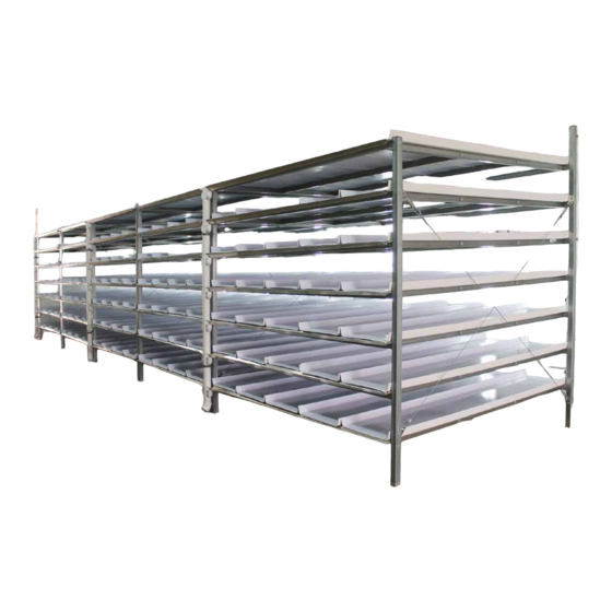
- Page 37 Additional Photo — Full System Revision date: 09.21.18 112712...
- Page 38 Additional Photo — Full System 112712 Revision date: 09.21.18...
- Page 39 Additional Photo — Full System Photo left shows the lower end of supply manifold. Photo above shows the manifold branch tubes as secured using the 113100 wire hangers. Revision date: 09.21.18 112712...
- Page 40 Additional Photo — Full System Photo left shows downspout and installed trays. Photo above shows seeded trays and gutter end of the system. When properly installed, curved end of each tray allows water to flow easily into gutter. Photo below shows close up of gutters and downspout drain elbows. 112712 Revision date: 09.21.18...
- Page 41 PAGE RESERVED FOR CUSTOMER NOTES AND RECORDS Revision date: 09.21.18 112712...
Need help?
Do you have a question about the FodderPro and is the answer not in the manual?
Questions and answers