Advertisement
Quick Links
HydroCycle 9" Pro
Vertical Microgreen
System (10')
©2018 Growers Supply
All Rights Reserved. Reproduction
is prohibited without permission.
Revision date: 09.25.18
STK#
DIMENSIONS
115277
51" W x 80" H x 118" L*
*Dimensions have been rounded and are approximate.
Dimensions are of the frame only; they do not include
adjustable feet or pvc plumbing and fixtures.
1
Advertisement

Related Manuals for FarmTek HydroCycle 9" Pro Vertical Microgreen System 10'


Summary of Contents for FarmTek HydroCycle 9" Pro Vertical Microgreen System 10'
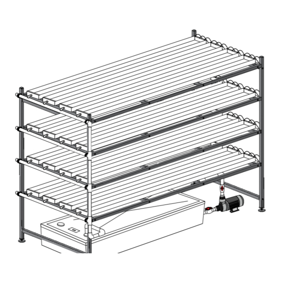
- Page 1 HydroCycle 9" Pro Vertical Microgreen System (10') STK# DIMENSIONS 115277 51" W x 80" H x 118" L* ©2018 Growers Supply *Dimensions have been rounded and are approximate. All Rights Reserved. Reproduction Dimensions are of the frame only; they do not include adjustable feet or pvc plumbing and fixtures.
- Page 2 Important Information READ THIS DOCUMENT BEFORE YOU BEGIN Thank you for purchasing the vertical microgreen system. When properly assembled and maintained, this product will provide years of reliable service. These instructions include helpful hints and important information needed to safely assemble and properly maintain the system. Please read these instructions before you begin.
- Page 3 Important Information PICTORIAL GUIDE The following graphics and photos will help identify the different parts of ATTENTION: A timer is required the microgreen system. (Some parts may not be shown.) To prevent mixing to cycle the water pump on and of fittings, select only those that are needed for each procedure.
- Page 4 Important Information PICTORIAL GUIDE (continued) 111303 111698 Ratchet Clamp WF8582 WF2392 WF3316 111045 WF1386 WF3420 WF1576 111302 WF2193 WF1570 WF6717 WF1030 111029 111030 WF6692 End Cap w/ Outlet End Cap No Outlet PVC PRIMER & PVC CEMENT Follow all directions printed on pvc primer and cement containers.
- Page 5 Assemble Frame 112772 ASSEMBLE SIDE FRAMES ATTENTION: The vertical tubes include holes 5/16" x 3" Flat of two different diameters. Install the larger Head Bolt Assemble frame on a flat, level surface for best results. hole to the outside to allow the flat head bolt to sit flush with the tube surface when installed.
- Page 6 Assemble Frame ASSEMBLE FRAME—INSTALL ADJUSTABLE FEET Assemble frame on a flat, level surface for best results. Complete these steps: 1. Add one FALB34B nut to the threaded stud of each 113030S01 foot and attach one foot to each 112477 insert. Bottom of Leg Tube...
- Page 7 Assemble Frame ASSEMBLE FRAME—continued Assemble frame on a flat, level surface for best results. Assistants are required to complete the frame assembly. FAG338B Complete these steps to assemble the main frame. 1. With assistance, stand the two side frames as shown (Fig. 1). 2.
- Page 8 Assemble Frame ASSEMBLE FRAME—continued FAG338B 4. Continue by installing all remaining cross braces between the side tubes at each level using the hex head bolts and flat washers. 5. Complete the frame assembly by installing the 112770 finishing plugs. Check all fasteners to ensure they are all tight. 6.
- Page 9 Assemble Channels ASSEMBLE THE CHANNELS ATTENTION: Complete this Required parts: procedure for the 111030 plain end caps only. Do not • 111030 End Cap (plain) drill holes in the 111029 end • 9/32" Drill Bit and Drill 111030 caps, which have an outlet. Complete these steps to prepare the 111030 end caps: ATTENTION: Cover the vice jaws or use material...
- Page 10 Assemble Channels ASSEMBLE THE GT80 CHANNELS (continued) ATTENTION: Attach one 111029 end cap (with outlet) and one 111030 plain end cap to each GT80 channel. 1. Using the assembled frame as a bench, place one channel on a bench or saw horses.
- Page 11 Install 2" Pipe Hangers INSTALL 2" DRAIN MANIFOLD HANGERS Channel Support Tube Horizontal Frame Brace 112838 100442 Complete these steps. Tek Screw Nut Setter 112539 2" Hanger 1. Determine which direction you want the drain manifold to slope toward and attach the high end pipe hanger first. See A. NOTE: Attach 112539 hanger flush with the top edge of the channel Channel Support Tube support tube and flush with the inside edge vertical frame tube.
- Page 12 Assemble and Attach 2" PVC Drain Manifold ATTENTION: During the assembly of the 2" drain ASSEMBLE AND ATTACH 2" PVC DRAIN MANIFOLD manifold, dry fit all pvc tubing and fittings before applying the pvc adhesive. Complete these steps: 1. Cut one piece of 2" pvc pipe to 53" and snap it into the hangers at one level of the frame. ATTENTION: Center the pvc pipe so 1"...
- Page 13 Assemble and Attach 2" PVC Drain Manifold ASSEMBLE AND ATTACH 2" PVC DRAIN MANIFOLD—continued 5. After confirming hole positions, use a 1-3/8" hole saw bit to drill the four (4) holes in the 2" tube. Example shows using a step bit to drill the holes. Keep all holes aligned during this step.
- Page 14 Assemble and Attach 2" PVC Drain Manifold ASSEMBLE AND ATTACH 2" PVC DRAIN MANIFOLD—continued 8. Attach all prepared pvc tubes to the frame. Align marks made in Step 2 with the installed hangers. See left diagram below. 9. Assemble the remainder of the main drain manifold as shown in the right diagram below. Dry fit all components before you permanently secure using pvc primer and WF6990 pvc cement.
- Page 15 Reservoir and Lid Preparation ATTENTION: Actual reservoir and lid DRILL RESERVOIR AND LID AND INSTALL FITTINGS may differ from the model used in the photos. Procedures are similar. Required tools: Drill, 5/16" drill bit, 2-1/4" and 2-1/2" hole saw bits 1.
- Page 16 Reservoir and Lid Preparation DRILL RESERVOIR AND LID AND INSTALL FITTINGS—continued 3. Finally, take the reservoir and drill the bulkhead fitting hole using a 2-1/4" hole saw bit. Review photos and diagrams for position. ATTENTION: Use the pump to determine the hole position on the reservoir. Set the pump and reservoir on the same level surface and align the inlet port of the pump with the spot on the reservoir where the bulkhead fitting will be installed.
- Page 17 Assemble and Install Nutrient Supply Manifold ASSEMBLE AND INSTALL NUTRIENT SUPPLY MANIFOLDS Complete these steps: WF4135 (1" PVC PIPE) 1. Gather the parts and construct one (1) upper manifold pipe and three (3) WF1570 WF6692 Upper Supply Manifold lower manifold pipes. Dry fit all parts. Do not cement at this time. ATTENTION: Cut the 1"...
- Page 18 Assemble and Install Nutrient Supply Manifold ASSEMBLE AND INSTALL NUTRIENT SUPPLY MANIFOLDS— CONTINUED 3. Align and evenly space all channels at each level. Channels will run parallel with each other and the 55" frame tubes. Insert drain elbows into Remove frame cross brace drain manifold to keep channels in place.
- Page 19 Assemble and Install Nutrient Supply Manifold ASSEMBLE AND INSTALL NUTRIENT SUPPLY MANIFOLDS—CONTINUED 110829 8. Choose one manifold and place it on a flat surface with the marks facing up. Upper manifold is shown below. Drill & Tap Combo Pak 9. Using the drill bit from the 110829 drill and tap combo pak, drill a hole at each of the marks. For best results, drill the manifold using a drill press. Repeat this step to drill the remaining supply manifolds.
- Page 20 Assemble and Install Nutrient Supply Manifold ASSEMBLE AND INSTALL NUTRIENT SUPPLY MANIFOLDS—CONTINUED 109242 WF4790 Adapters 12. Wrap the threaded end of each 109242 adapter three or four times with the WR1095 tape. Wrap in a direction Key Punch that will not loosen when adapter is installed. There are 48 adapters needed for this system. WR1095 Tape Wrap threads of adapters with tape.
- Page 21 Assemble and Install Nutrient Supply Manifold ASSEMBLE AND INSTALL NUTRIENT SUPPLY MANIFOLDS—CONTINUED 15. Assemble the four (4) valve assemblies as shown. 113535 AC2804 111074 Step 18: Measure distance needed to connect manifolds. Pipe must be long 111698 Clamps enough to insert into each fitting. 16.
- Page 22 Assemble and Install Nutrient Supply Manifold ASSEMBLE AND INSTALL NUTRIENT SUPPLY MANIFOLDS—CONTINUED 19. After confirming length, disassemble as needed to apply pvc primer and cement and reassemble. Remove and reinstall lower manifold as needed. 20. Continue working down the end frame and adding the 1" vertical manifold pipes. Dry fit all pipes before applying the pvc primer and cement.
- Page 23 Cut and Install 1/4" Nutrient Supply Tubes CUT AND INSTALL THE 1/4" MICRO TUBES Complete these steps: 1. Using the 109170 tube cutter, cut a section of 111046 (1/4") micro tubing (not to exceed 20") to determine how long you want each 1/4" supply tube to be. ATTENTION: Use photos and diagram to decide where you want micro valve positioned in each supply tube for a uniform look.
- Page 24 Level Frame and Set Slope LEVEL FRAME AND SET SLOPE To ensure that water flows through and properly drains from the plant channels, a 1/2" slope toward the drain end of the system is required. Frame must also be level from side-to-side when viewed from the end. Complete these steps: 1.
- Page 25 Install the Main Pump and Plumbing INSTALL THE MAIN PUMP & PLUMBING Gather parts identified in the photo and construct main pump supply plumbing. Review assembly and installation WARNING: All electrical notes that follow before you begin. For best results, complete this procedure after setting frame slope. wiring to be completed •...
- Page 26 Assemble and Attach 2" PVC Drain Manifold ASSEMBLE AND ATTACH PVC DRAIN MANIFOLD Complete these steps: 1. Measure, cut, and dry fit the remaining sections of the 2" pvc drain manifold as shown in the photos below. 2. Once the fit is confirmed, disassemble and apply pvc primer and WF6990 cement to drain tubes and fittings.
- Page 27 Install the Air Pump and Tubing ATTENTION: Always position the air pump above the nutrient level to prevent siphoning of the reservoir. ATTACH THE AIR PUMP AND AERATOR STONES 110077 Air For optimal system performance and to extend the life of the nutrient solution through increased Stone oxygenation, an aerator pump and aerator stones are included.
- Page 28 Basic System Check Before Start Up WARNING: KEEP ALL ELECTRICAL CORDS AND CONNECTIONS OUT OF RESERVOIR. CONSULT THE SERVICES OF A QUALIFIED ELECTRICIAN TO ADEQUATELY AND SAFELY CONNECT PUMPS TO POWER. ALL ELECTRICAL CIRCUITS SHALL BE DESIGNED IN ACCORDANCE WITH LOCAL AND REGIONAL BUILDING CODES AND STANDARDS. Basic System Check and Operation Complete these steps to check and start up the system: 1.
- Page 29 Operational and Maintenance Information General Cleaning and Maintenance Instructions Clean the Filter Screen and Housing For best results, clean the filter screen regularly or when the flow rate For optimal performance and to increase yields, check and clean the system changes unexpectedly.
- Page 30 Operational and Maintenance Information RESERVOIR CLEANING AND MAINTENANCE Clean the reservoir periodically to maximize plant growth and to minimize system contamination. The steps that follow can be used to change nutrient solution and to pump the reservoir for cleaning and typical maintenance. Cleaning the filter is strongly recommended after cleaning the reservoir. Shutoff Valve 1.
- Page 31 Quick Start Guide ATTENTION: A timer is required Sample System — Fully Assembled to cycle the water pump on and off. If you did not purchase a timer, contact your sales representative to purchase the 112531 timer. *Timer not included. Additional purchase required.
-
Page 32: Frame Dimensions
Frame Dimensions Side View—Frame End View—Frame Length Width Approximately 118" Approximately 51" (frame only) (frame only) 16" 16" 16" Approximately 24"– actual distance depends on adjustable feet settings. 115277 Revision date: 09.25.18... - Page 33 Full Frame Diagram ATTENTION: The vertical tubes include 48" Cross Brace holes of two different diameters. Install FD15CMGL04800S1 the larger hole to the outside to allow the flat head bolt to sit flush with the tube 115" Side Tube surface when installed. FD15LMGL11500S2 112770 Finishing Cap...
- Page 34 Supply & Drain Manifolds Only Supply Drain 115277 Revision date: 09.25.18...
- Page 35 End View — 1" Supply Manifold with Channels WF1570 (1) 111047 (Micro Valve) WF4135 (1" PVC PIPE) 111046A (Tubing) 111046A WF6692 (1) 111698 (1) 113535 (1) 111698 (1) 1" PVC 109242 Manifold AC2804 (1) Adapter 112538 WF4135 (1" PVC PIPE) WF1380 (3) Reservoir with Lid Revision date: 09.25.18...
- Page 36 End View — 2" Drain Manifold with Channels WF6717 (4) WF1576 112539 (8) WF1386 Assembled 9" Channel 111560 (2" PVC PIPE) 111560 (2" PVC PIPE) Minimum 6" tube. Tube should extend through lid at least 2" but WF1576 WF1576 remain above solution level. Reservoir with Lid 115277 Revision date: 09.25.18...
- Page 37 Side View with Channels WF1030 WF2190 WF3420 111045 111045 Bulkhead Fitting & 113537 113536 WF2193 Adapter WF1380 WF3316 Revision date: 09.25.18 115277...
- Page 38 Additional Photos — Supply Manifold and Pump ATTENTION: Actual tank may differ from example shown. Pipe length and position of components depends on assembly. Completed assembly of actual system may differ from the example shown in photos throughout this guide. Both WF3316 valves to remain open during operation.
- Page 39 PAGE RESERVED FOR CUSTOMER NOTES AND RECORDS Revision date: 09.25.18 115277...
Need help?
Do you have a question about the HydroCycle 9" Pro Vertical Microgreen System 10' and is the answer not in the manual?
Questions and answers