Table of Contents
Advertisement
Quick Links
Version History
Issue Number
Version A
Version B
Version C
UK and EMEA: NetVu Ltd. www.netvu.org.uk
No 1 Thellow Heath Park, Northwich Road, Northwich, Cheshire. CW9 6JB
TransVu 3 DVR Installation Manual
TransVu 3 DVR
Installation Manual
TV/MAN/002/C
Date
nd
2
November, 2020.
th
15
December, 2020 Author: P Ridgeon
st
21
December, 2020 Author: P Ridgeon
Comments
Author: P Ridgeon
21/12/2020
Page 1 of 66
Advertisement
Table of Contents

Subscribe to Our Youtube Channel
Related Manuals for NetVu TransVu 3


Summary of Contents for NetVu TransVu 3
-
Page 1: Version History
TransVu 3 DVR Installation Manual 21/12/2020 Page 1 of 66 TransVu 3 DVR Installation Manual TV/MAN/002/C Version History Issue Number Date Comments Version A November, 2020. Author: P Ridgeon Version B December, 2020 Author: P Ridgeon Version C December, 2020 Author: P Ridgeon UK and EMEA: NetVu Ltd. -
Page 2: Table Of Contents
Mounting the Baseplate ....................... 9 Care in Feeding Cables ....................... 9 Installing the Hard Drive ......................10 Connecting to the TransVu 3 ..................... 10 Analogue Camera Connector Layout ..................11 Waterproof Ethernet Connector Layout .................. 12 Power Connector Layout......................12 37-Way Multi-Purpose Connector Layout ................ - Page 3 Title TransVu 3 DVR Installation Manual Page 3 of 66. Maintain Page ........................30 Features Page ........................31 Audio Page ..........................32 Power Management Page ...................... 33 Serial Ports Page ........................34 GPS Page ..........................35 Accelerometer Page ......................35 Display Pages ........................
-
Page 4: Introduction
Part of the NetVu Connected product range, the TransVu 3 is fully network capable and supports the Internet standard TCP/IP protocol. As the TransVu 3 is a mobile product the unit can be accessed via wireless LAN or GSM / GPRS / CDPD / UTMS / HSDPA. Supporting up to twelve video inputs (analogue or IP), line and microphone audio inputs, six alarm inputs and intelligent power management the TransVu 3 is a powerful, cost effective transportation recorder. - Page 5 This section contains the regulatory declarations for the EU for the TransVu 3. This product is marked with the CE symbol and indicates compliance with all applicable Directives. A “Declaration of Conformity” is held at NetVu Ltd, No 1 Thellow Heath Park, Northwich Road, Northwich, Cheshire, CW9 6JB.
- Page 6 CE Mark If this product is marked with the CE symbol it indicates compliance with all applicable directives. Directives 2014/30/EU, 2014/35/EU. A ‘Declaration of Conformity’ is held at NetVu Ltd, No 1 Thellow Heath Park, Northwich Road, Northwich, Cheshire, CW9 6JB.
-
Page 7: Installing Transvu 3
Installing TransVu 3 Before you start check the contents of the box The box should contain the following items TransVu 3 DVR, including base plate, 4 off shock mounts and shock mount fittings (fitted to the chassis). Accessories: Hard Drive Caddy Key •... - Page 8 It should be mounted as low as possible within the vehicle, on a secure base free from resonance and secondary vibrations. The TransVu 3 is secured to the mounting plate via four shock absorbing fixings. This dramatically reduces the effects of vehicle borne vibrations and enables the system to operate in harsh shock environments.
-
Page 9: Mounting The Baseplate
Title TransVu 3 DVR Installation Manual Page 9 of 66. Vibration will cause the TransVu 3 to move on the shock mounts. Allow clearance around the unit to accommodate this movement. It is recommended that a minimum fitment volume of 330mm (13 ”) x 300mm (12 “) x 130mm (5 “) is allowed. -
Page 10: Installing The Hard Drive
3. Carefully slide the caddy back into the TransVu 3. Remember to lock the caddy into the TransVu 3 using the keylock. Failure to do so will prevent the unit starting up. -
Page 11: Analogue Camera Connector Layout
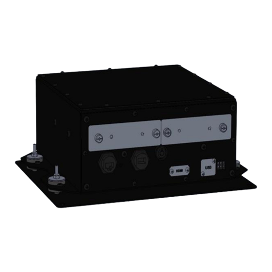
Title TransVu 3 DVR Installation Manual Page 11 of 66. 12 Off analogue camera connections Net 2: 10/100Mb/s Ethernet port 10-Way power connector 37-Way multi-purpose connector 15-Way com-port expansion connector Analogue Camera Connector Layout The layout of each Analogue Camera Connector is as follows:... -
Page 12: Waterproof Ethernet Connector Layout
Title TransVu 3 DVR Installation Manual Page 12 of 66. Waterproof Ethernet Connector Layout The layout of the Waterproof Ethernet Connector is as follows: Power Connector Layout The layout of the Power Connector is as follows: Pin 1: Supply Voltage Input Positive (+ve) Connection... -
Page 13: 37-Way Multi-Purpose Connector Layout
Title TransVu 3 DVR Installation Manual Page 13 of 66. 37-Way Multi-Purpose Connector Layout The layout of the 37 Way Connector is as follows: Signal Description Signal Description MONITOR OUTPUT CANBUS LO GROUND CANBUS HI COM 1 RS-232 TX DATA... -
Page 14: Connecting Analogue Cameras
IP cameras may be connected to an Ethernet Network switch. The network switch may in turn be connected to any of the three network ports provided on the TransVu 3. Commercially manufactured network patch cables, with either RJ45 connectors may be used for this connection. -
Page 15: Connecting An Hdmi Video Monitor
Page 15 of 66. Connecting an HDMI Video Monitor An HDMI monitor may be connected to TransVu 3 using a commercially made HDMI cable. The HDMI socket is located beneath a blanking plate below the hard disk drive caddy. Connecting a Composite Video Monitor... -
Page 16: Ignition Sense Input
Title TransVu 3 DVR Installation Manual Page 16 of 66. (Software Adjustable Gain, AGC and Bias Disable) Impedance: 10 k Ohms Recommended cable: Single core screened audio cable Ignition Sense Input To detect ignition switch-off and power down after a set period of time. Active high input requiring... -
Page 17: End Of Line (Eol) Circuitry
Title TransVu 3 DVR Installation Manual Page 17 of 66. P19 Alm Input 4 P15 Alm Input 3 P14 Alm Input 1 P28 Alm Gnd P29 Alm Input 2 P36 Alm Input 5 P37 Alm Input 6 End of Line (EOL) Circuitry The following describes the EOL tamper alarms circuitry needed when EOL has been configured. -
Page 18: Serial Port
Title TransVu 3 DVR Installation Manual Page 18 of 66. Serial Port Three RS232 serial ports are available, of which COM 1 defaults to the DEBUG function. Baud Rate 115200 Data Bits Parity Bits Stop Bits Flow Control none NetVu Ltd. www.netvu.org.uk... -
Page 19: Relay Output (Solid State)
Title TransVu 3 DVR Installation Manual Page 19 of 66. Relay Output (Solid State) This is a single pole solid state relay which can be activated by the software based upon user- defined events. Note: The relay is polarised and must always be connected in one of the ways shown below. -
Page 20: Connecting Vehicle Power
Title TransVu 3 DVR Installation Manual Page 20 of 66. Connecting Vehicle Power TransVu 3 is designed to run on vehicles with a negative earth or negative ground system. LEDs Six status LEDs are visible on the front panel of the unit. -
Page 21: Configuring Transvu 3
If a permanent IP address is not assigned to the unit, it will attempt to contact the DHCP server every time it starts up, and periodically thereafter. Accessing the Configuration Pages The TransVu 3 is configured using the on-board configuration pages. NetVu Ltd. www.netvu.org.uk No 1 Thellow Heath Park, Northwich Road, Northwich, Cheshire. CW9 6JB... -
Page 22: System - Attributes Page
1. Launch a web browser, preferably on a PC on the same subnet as the unit. 2. Type the IP address (or DNS name if there is no fixed IP address) of the unit into the address bar and press enter. The Main menu of the TransVu 3 will be displayed. System – Attributes Page From the main menu of the camera, click on Configuration. - Page 23 The Time and Date page allows the unit time and date settings to be adjusted, including setting the time zone. The User Accounts page allows user names and password credentials to be set for the TransVu 3. The Maintain page allows the current configuration to be saved, and for previously saved settings to be loaded.
-
Page 24: Attributes
Sub Net: This is the subnet mask for the unit. MAC Address: This is the MAC address assigned to the unit. Zero conf address: The starting IP address of the closed IP network for this TransVu 3. Software Revision: The Software version of the TransVu 3. -
Page 25: Status Pages
Earliest Recording: Displays the date and time of the earliest recording held on the unit. Time Since Last Reset: the amount of time that has passed since the last reset of the TransVu 3. Time/Date (Green): Links to the System->Time and Date page. - Page 26 MDNS Listings: Opens the MDNS listings page. Auto Configuration: opens the Auto Configuration page. Most of these pages have no installer application, unless guided by NetVu technical support. NetVu Ltd. www.netvu.org.uk No 1 Thellow Heath Park, Northwich Road, Northwich, Cheshire. CW9 6JB...
- Page 27 Title TransVu 3 DVR Installation Manual Page 27 of 66. Logs Page The logs page allows various diagnostics reports to be run, under the guidance of NetVu Support. There are no Installer settings on this page. Upload Page NetVu Ltd. www.netvu.org.uk...
-
Page 28: Time And Date Page
Title TransVu 3 DVR Installation Manual Page 28 of 66. This page provides a means of transferring new files to the unit, without having to use FTP. This can be used to update the software of the camera, install PowerScript files etc. -
Page 29: User Accounts Page
Title TransVu 3 DVR Installation Manual Page 29 of 66. SNTP Server: A Simple Network Time Protocol (SNTP) server allows external devices to connect and set their current date and time settings to that of the SNTP. If required, enter the SNTP server IP address here. -
Page 30: Maintain Page
Title TransVu 3 DVR Installation Manual Page 30 of 66. Delete (Yellow): Delete an existing account. Account Info (Blue): Displays a window describing the types of account. Maintain Page This menu allows the unit to be reset and a software upgrade to be performed via a connected USB device. -
Page 31: Features Page
Title TransVu 3 DVR Installation Manual Page 31 of 66. Note: Selecting the Default button will cause the system to reboot. Server Reset (Red): Select to cycle the power to the unit. IMPORTANT: To upgrade the unit, insert a media device containing relevant software upgrades and select ‘Reset‘. -
Page 32: Audio Page
Title TransVu 3 DVR Installation Manual Page 32 of 66. ARP Cache Size: This limits the number of cache entries available in the ARP table. It defaults to 256 which is adequate for most instances. Consult your network administrator for advice about whether this should be increased. -
Page 33: Power Management Page
Title TransVu 3 DVR Installation Manual Page 33 of 66. Audio Recording: When Enabled, this will record all audio received by the unit to the HDD. Please note, enabling this option will reduce the record duration. Record uncompressed: Select this option to record audio in an uncompressed format, note that this will significantly increase the disk space used. -
Page 34: Serial Ports Page
Title TransVu 3 DVR Installation Manual Page 34 of 66. 12V Output: Enables or disables the auxiliary 12 Volt supply output of the unit. Power Retry: When enabled, if a camera power fault is detected the unit will retry to connect the... -
Page 35: Gps Page
Title TransVu 3 DVR Installation Manual Page 35 of 66. GPS Page The GPS page is used to configure the interface of the unit with an external GPS receiver. Sync time on startup: When enabled, the clock of the TransVu will be synchronised to the GPS time when the TransVu starts up. -
Page 36: Display Pages
Title TransVu 3 DVR Installation Manual Page 36 of 66. Max G Setting: This value is set to match the accelerometer hardware fitted in the factory. Consequently this is not a user-adjustment and should not be changed by the user. -
Page 37: Viewer Defaults Page
Title TransVu 3 DVR Installation Manual Page 37 of 66. Viewer Defaults Page This menu allows configuration of settings for the Viewer function. Startup Multi Display: When accessing the Viewer function, select the display format which will initially be displayed. -
Page 38: Camera Pages
Title TransVu 3 DVR Installation Manual Page 38 of 66. This page configures the spot monitor display. Spot monitor text: Enables/Disables text display on the spot monitor. Show camera title: When ticked, the camera title is displayed. Show system time: When Ticked, the system time is displayed. -
Page 39: Camera - Overview Page
Mono – monochrome analogue camera • Colour – colour analogue camera • IP Camera Remote Codec – a NetVu SmartVu IP camera • IP Address: The IP address of the camera. IP Port: The IP port of the camera. IP Channel: The physical channel on the camera to use. If the IP Address above is a multichannel device, this setting specifies which channel to use. -
Page 40: Camera - Patrols Page
Title TransVu 3 DVR Installation Manual Page 40 of 66. Camera – Patrols Page This page is used to program patrols of PTZ cameras connected to the unit. Home Delay: Sets a period in seconds of inactivity, after which the PTZ camera will return to its... -
Page 41: Alarm Setting Pages
Title TransVu 3 DVR Installation Manual Page 41 of 66. Alarm Setting Pages The Alarm Settings menus allow configuration of the unit’s alarm functionality. Individual alarm inputs and alarm zones can be configured. Global relays can be activated and the Activity grid set Refer to the individual menus for further details. - Page 42 Title TransVu 3 DVR Installation Manual Page 42 of 66. These triggers include: Activity Detection events • Video Motion Detection events • Physical Alarm Input activation – local alarm inputs on the TransVu and remote (modbus) • alarm inputs Camera Failure •...
- Page 43 Title TransVu 3 DVR Installation Manual Page 43 of 66. Single region events, multi region events and variables can be viewed using the drop-down list. Base Channel: Where the trigger type is an alarm input this field sets the starting number from...
-
Page 44: Expression Editor Page
Title TransVu 3 DVR Installation Manual Page 44 of 66. Set: If ticked, actions will be taken if the TransVu is in SET mode (can be controlled using Alarm input 6, an SIA Alarm Panel or some other input). Unset: If ticked, actions will be taken if the TransVu is in UNSET mode (can be controlled using Alarm input 6, an SIA Alarm Panel or some other input). - Page 45 Title TransVu 3 DVR Installation Manual Page 45 of 66. The new approach allows the monitoring of alarm inputs local to the unit itself (such as physical alarm inputs, Video Motion Detection and camera failure), alarm inputs at each camera and virtual alarm inputs and variables received over the network from other third-party systems.
-
Page 46: Activity Page
Title TransVu 3 DVR Installation Manual Page 46 of 66. The virtual LED to the right of each expression shows it’s current state – Green for Inactive and Red for Active. The number of recent transitions of the expression (inactive to active and vice versa) is also shown. -
Page 47: Vmd Setup Page
Title TransVu 3 DVR Installation Manual Page 47 of 66. Clicking Reload Img (Red) will reload the image behind the grid editor. Clicking Set All (Green) will set all the cells in the grid editor to active. Clicking Clear All (Yellow) will clear (i.e. de-select) all the cells in the grid editor. -
Page 48: Alarm - Schedule Page
Title TransVu 3 DVR Installation Manual Page 48 of 66. Pixel Change (%): Percentage value of the overall change required, over the complete range • of black to white, to be included in the pixel count. A 100% pixel change would be from black to peak white. -
Page 49: Inputs Page
Force Night: Clicking on this button forces the unit in to “night” mode. Force Weekend: Clicking on this button forces the unit in to “weekend” mode. Inputs Page This menu allows configuration of the alarm settings, refer to ‘Installing the TransVu 3’ for hardware installation guidance. NetVu Ltd. www.netvu.org.uk... -
Page 50: Alarm Inputs Page
Enter the time in seconds for this extension. Alarm Inputs Page This page is for the use of NetVu engineers only. Virtual Alarm Inputs In addition to physical alarm inputs and VMD expressions can be written using virtual alarm inputs. - Page 51 Title TransVu 3 DVR Installation Manual Page 51 of 66. USERVIRTUAL ADMINVIRTUAL These can be used by the expression system to perform any required action. Example expressions: These expressions close/open relays when the virtual events fire. The CGI's can set/clear/pulse the virtual alarms as required.
-
Page 52: Global Relays Page
Title TransVu 3 DVR Installation Manual Page 52 of 66. A test webpage which drives the user virtual events is available in the TransVu webpages accessible from: <nvr ip address>/gui/frmpages/gui_virtual_alarm.html Global Relays page This menu allows configuration of the default relay actions supported on the unit. The unit supports two onboard relay connections and global relay settings. -
Page 53: Network Pages
Network – Setup page The page configures the network connection to the TransVu 3 and displays current settings. System Name: This field can be edited to allocate a name to the unit. This would be used if accessing the unit using a Domain Name Server (DNS). The setting is the same as the system name displayed in the System Attributes menu and defaults to the unit serial number. -
Page 54: Email Page
Gateway: If the unit communicates with a host on another subnet, it will talk through a device called a router which links the TransVu 3 subnet to other networks, the IP address of this router is called a default gateway. - Page 55 Title TransVu 3 DVR Installation Manual Page 55 of 66. Connection Profile: The name of the profile selected. Different profiles can be created so that different events send emails to different users. Mail Server Address: The IP address or domain name of the mail server to be used.
-
Page 56: Multicast Page
Log Email : Tick to include the sending of an email in system logs. Multicast page The multicast page is for the use of NetVu Ltd engineers only and no changes should be made to this page before contacting NetVu Technical Support. -
Page 57: Arc Configuration Page
Title TransVu 3 DVR Installation Manual Page 57 of 66. Telnet: putting a tick in this box prevents Telnet access to the NVR unless a user name and password has been created for Telnet access in the User Accounts page. -
Page 58: Taip Broadcast Setup Page
Title TransVu 3 DVR Installation Manual Page 58 of 66. Two RVRC may be configured to allow for redundancy of signalling. For each RVRC the following may be configured: Host IP: The Static IP address of the RVRC. Port: The Netowrk port of the RVRC to which alarm event notifications will be sent. -
Page 59: Ftp Download Page
Title TransVu 3 DVR Installation Manual Page 59 of 66. The page sets the broadcast port used. FTP download page Video PAR files from the TransVu can be uploaded to an FTP server. This page configures this feature. Current Status: Shows current FTP download status. -
Page 60: Image Profiles - Profile Setup Page
Title TransVu 3 DVR Installation Manual Page 60 of 66. FTP Root Drive and Directory: The root drive and directory in the FTP server in to which files will be downloaded. Username: The User name to be used for the FTP server. - Page 61 Title TransVu 3 DVR Installation Manual Page 61 of 66. The MultiMode recording feature offers the ability to set different recording rates, resolutions and compression formats across unset, set and override modes for each individual camera. By varying the quality, bit rate and file size of recorded images, the MultiMode function enables the recording capabilities of the unit to be greatly increased.
-
Page 62: Live Viewer Page
Title TransVu 3 DVR Installation Manual Page 62 of 66. Stream Profiles : The following settings configure live video streams taken from the unit. Compression: Select image compression format Resolution: Select image resolution format BitRate_kbps: If MPEG4/H.264 is selected, the figure entered here will be the bit rate allocated. - Page 63 Title TransVu 3 DVR Installation Manual Page 63 of 66. Select the camera to be viewed using the cam drop-down box at the bottom of the page. The resolution of the image may be selected using the res control. NetVu Ltd. www.netvu.org.uk...
-
Page 64: Glossary
Title TransVu 3 DVR Installation Manual Page 64 of 66. Glossary AGC Automatic Gain Control ALPR Automatic License Plate Recognition (US) AMS Archive and Management System ANPR Automatic Number Plate Recognition (UK and Europe) AoE ATA over Ethernet ARC Alarm Receiving Centre... - Page 65 Title TransVu 3 DVR Installation Manual Page 65 of 66. IR Infrared IRE A unit used in the measurement of composite video signals LAN Local Area Network LLDP Link Layer Discovery Protocol MAC Media Access Control MDNS Multicast Domain Name System...
- Page 66 Title TransVu 3 DVR Installation Manual Page 66 of 66. TTL Time To Live TVL Television Lines UDP User Datagram Protocol UPS Uninterruptible Power Supply VSaaS Video Surveillance as a Service VESA A family of standards defined by the Video Electronics Standards Association...
Need help?
Do you have a question about the TransVu 3 and is the answer not in the manual?
Questions and answers