Cabletron Systems SmartSTACK 10 ELS10-26 Getting Started
Enterasys smartstack 10 els10-26: quick start
Hide thumbs
Also See for SmartSTACK 10 ELS10-26:
- Reference manual (170 pages) ,
- User manual (116 pages)
Table of Contents
Advertisement
Quick Links
Getting Started with the SmartSTACK 10 ELS10-26
ELS10-26TX
9032245-01
PORT STATUS MODE
TX ACT FDX MON
1
3
5
7
9
11
13
2
4
6
8
10
12
14
RX COL 100 USR
STATUS
PWR
CPU
RESET
COM
2X
4X
6X
8X
10X
12X
14X
15
17
19
21
23
25
26
16
18
20
22
24
MON
27
10BASE-T/
100BASE-TX
16X
18X
20X
22X
24X
MONX
26X
FEPIM
27
Advertisement
Table of Contents

Related Manuals for Cabletron Systems SmartSTACK 10 ELS10-26


Summary of Contents for Cabletron Systems SmartSTACK 10 ELS10-26
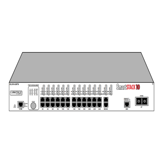
- Page 1 Getting Started with the SmartSTACK 10 ELS10-26 ELS10-26TX PORT STATUS MODE TX ACT FDX MON RX COL 100 USR STATUS RESET 9032245-01 10BASE-T/ 100BASE-TX MONX FEPIM...
-
Page 3: Fcc Notice
Only qualified personnel should perform installation procedures. NOTICE Cabletron Systems reserves the right to make changes in specifications and other information contained in this document without prior notice. The reader should in all cases consult Cabletron Systems to determine whether any such changes have been made. - Page 4 CABLETRON SOFTWARE PROGRAM LICENSE LICENSE. You have the right to use only the one (1) copy of the Program provided in this package subject to the terms and conditions of this License Agreement. You may not copy, reproduce or transmit any part of the Program except as permitted by the Copyright Act of the United States or as authorized in writing by Cabletron.
-
Page 5: Table Of Contents
Contents Welcome to SmartSTACK 10 ELS10-26 ... 1 Getting Help ... 1 Setting Up and Powering Up the ELS10-26 ... 2 Attaching Power Cord and Connecting to a Power Source ... 2 Checking the Power-up Diagnostics Sequence... 2 Connecting UTP Cables ... 4 Installing a Fast Ethernet Port Interface Module (FEPIM) ... - Page 6 – iv –...
-
Page 7: Welcome To Smartstack 10 Els10-26
ELS10-26 into your network. This guide will provide you with what you need to know to: • set up and power up the SmartSTACK 10 ELS10-26 • connect devices to the SmartSTACK 10 ELS10-26 •... -
Page 8: Setting Up And Powering Up The Els10-26
A power cord is provided with the ELS10-26. Attach the power cord to the power cord connector on the back of the ELS10-26. The ELS10-26 is not equipped with an on/off switch. To power-up the unit, connect the power cord to a 120 VAC or 240 VAC single- phase stress grounded outlet. - Page 9 4. All Port Status lights remain on. 5. All Link LEDs flash, four at a time, in sequence, from left to right. 6. After several more seconds, the CPU LED will stay on, indicating that the power-up diagnostics sequence is complete. 7.
-
Page 10: Connecting Utp Cables
ELS10-26 RJ-45 Port Note: RX+/RX- and TX+/TX- must share a common color pair. – 4 – Connecting UTP Cables Before connecting a segment to the ELS10-26, check each end of the segment to verify wire crossover. Caution: To establish a link, you must have an odd number of crossovers (preferably one) between 10BASE-T devices of the same type (i.e., from repeater to repeater or transceiver to transceiver). -
Page 11: Installing A Fast Ethernet Port Interface Module (Fepim)
Installing a Fast Ethernet Port Interface Module (FEPIM) Only qualified personnel should perform installation procedures. The ELS10-26 provides a slot for a Cabletron FEPIM (Fast Ethernet Port Interface Module). The ELS10-26 is shipped without an FEPIM. To install an FEPIM, follow the procedure below: 1. -
Page 12: Connecting A Utp Segment To Fe-100Tx
Refer to the schematic of a crossover cable shown on page 4. If the wires do not cross over, use the switch on the FE-100TX to internally cross over the RJ45 port. -
Page 13: Connecting A Multimode Segment To The Fe-100Fx
Connecting a Multimode Segment to the FE-100FX The FE-100FX has an SC style network port. Cabletron Systems supplies fiber optic cable that uses SC style connectors that are keyed to ensure proper crossing over of the transmit and receive fibers. Caution: An odd number of crossovers (preferably one) must be maintained between devices so that the transmit port of one device is connected to the receive port of the other device and vice... -
Page 14: Connecting The Local Console Manager To A Terminal
Connecting the Local Console Manager to a Terminal The Local Console Manager (LCM) is a command-line interface for configuring, monitoring, and managing the ELS10-26 through the out-of-band RS232C connection on the front panel. To connect LCM: 1. Connect your VT series terminal or terminal emulator to the out-of-band management RS232C port on the front panel of the ELS10-26 using the standard twisted pair cable with RJ45 connectors shipped with the unit. -
Page 15: Lcm Commands
LCM Commands addresses display Displays learned addresses. Options: ADDRESS MASK Example: address display any Enter arp display Displays the ARP table. Example: arp display Enter baud Displays the current baud rate of your LCM console connection, and allows you to change the baud rate. Options: 2400 4800... - Page 16 exit (logout) Allows you to log out of your current LCM session. Example: exit Enter help Displays the available LCM commands. You can also type a question mark ( ? ) to display the available LCM commands. Example: help Enter ident Displays the ELS10-26’s serial number, the FE up-link module number (if installed), power-up test codes, and diagnostic information.
- Page 17 sttimer Displays the current Spanning Tree Address Table aging time, and allows you to enter a new aging time. Example: sttimer 300 Enter time Allows you to display or set system time. Option: HHMMSS Example: time 113000 Enter traceroute Allows you to print the route that packets take to the host. Options: -m MAX_TTL -q NQUERIES...
- Page 18 – 12 –...
Need help?
Do you have a question about the SmartSTACK 10 ELS10-26 and is the answer not in the manual?
Questions and answers