Table of Contents
Advertisement
Available languages
Available languages
Quick Links
Advertisement
Table of Contents

Related Manuals for HMS BE5833


Summary of Contents for HMS BE5833
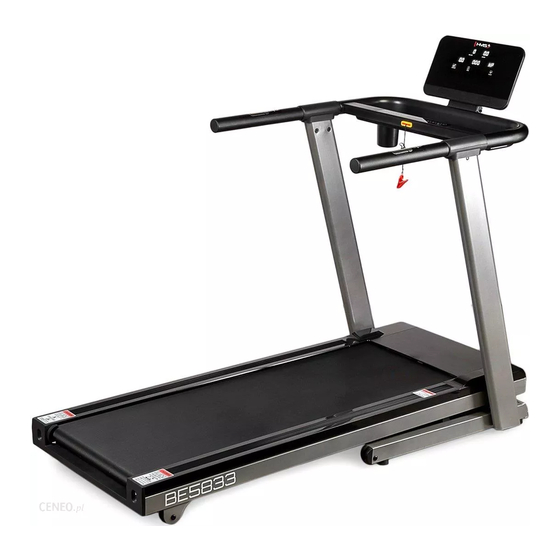
- Page 1 BE5833...
- Page 2 Uwagi dotyczące bezpieczeństwa 1. Przed pierwszym użyciem należy zapoznać się dokładnie z instrukcją i zachować ją na przyszłość. 2. Należy uwzględnić wszystkie ostrzeżenia i środki ostrożności łącznie z etapami montażu. Z maszyny można korzystać jedynie zgodnie z jej przeznaczeniem. 3. Mając na względzie własne bezpieczeństwo, produkt należy zmontować i użytkować zgodnie z niniejszą...
-
Page 3: Lista Części
Lista części NAME Rama bieżni Platforma Kolumna (L) Kolumna (R) Rama konsoli Tylna osłona komputera Zatrzask Osłona Osłona silnika pochylni Wspornik Śruba M12×Φ14×35×19 Śruba M8×75 Śruba M8×15 Śruba M8×20 Śruba M8×15 Śruba M6×15 Śruba M8×50×20 Podkładka Φ12 Śruba M8×30×20 Śruba M6×30×Φ16 Śruba M5×10 Śruba M4×10 Śruba ST4×16... - Page 4 Sterownik Klucz bezpieczeństwa Przewód Przewód Wyłącznik Przycisk resetu Przewód zasilający Pilot przewód Zasilacz Przednia rolka Tylna rolka Osłona kółek transportowych Silnik Gniazdo klucz Pas bieżny Pasek silnika Osłona silnika Tylna osłona Szyna boczna Górna osłona uchwytów Dolna osłona uchwytów Osłona konsoli Tylna osłona konsoli Osłona konsoli Uchwyt na butelkę...
- Page 5 Zestaw zawiera M8X15 Bieżnia Kolumny Zestaw narzędzi Konsola Klucz Bezpieczeństwa Smar do bieżni Zestaw narzędzi Trzpień 1 szt. Krótka śruba z łbem sześciokątnym(M8*20)4pcs Klucz imbusowy S6 1szt Klucz imbusowy S5 1szt Śruba imbusowa(M8*50*20)4szt Śruba imbusowa(M8*15)2szt...
-
Page 6: Opis Produktu
Opis produktu Dane techniczne Wymiary bieżni: 171 x 81,5 x 138,7 cm Maksymalna waga użytkownika: 120 kg Waga netto: 79,5 kg Waga brutto: 91 kg Pas bieżny: 142 x 50 cm... - Page 7 Montaż Krok 1 Wyjmij urządzenie z opakowania I umieść na płaskiej suchej nawierzchni. Krok 2 Unieś płytę bieżni do momentu zablokowania wspornika teleskopowego. Połącz przewody bazy z końcówkami znajdującymi się w kolumnie. Przykręć kolumny do bieżni używając 4 śrub imbusowych M8*50*20 od wewnętrznej strony oraz 2 śrub M8*15.
- Page 8 Krok 4 Unieś konsolę I używając trzpienia zabezpieczającego zablokuj ją wkładając trzpień z lewej strony kontroli. Krok 5 Sprawdź czy wszystkie śruby są dokręcone. Gotowe Smarowanie Bieżnia jest fabrycznie nasmarowana. Zaleca się jednak regularne sprawdzanie smarowania bieżni, aby zapewnić optymalną pracę urządzenia. Zazwyczaj nie jest konieczne smarowanie bieżni w pierwszym roku lub pierwszych 500 godzinach pracy.
- Page 9 Wyświetlacz i funkcję komputera Wyświetlacz i funkcję komputera Kąt nachylenia „+” „-„ Programy Stop Start Mode Prędkość „+” „-„ Opis panelu P0:program manualny; P1-P36 auto programy;3 programy użytkownika; body fat wyświetlacz LED, 12 przycisków; prędkość:1.0~18.0KM/H,Kąt nachylenia :0-15%; Funkcja zapobiegania przeciążeniom, funkcja auto test; Funkcja konwersji prędkości I dystansu;...
- Page 10 Opis przycisków funkcyjnych “PROG”:Służy do wyboru programu, zapętlenia P1~P36,U01,U02,U03,FAT; “MODE”:naciśnij aby przejść do trybu manualnego lub by rozpocząć ćwiczenia z odliczeniem pożądanej wartości: Odliczanie czasu →Odliczanie przebytego dystansu→Kalorii Po zatwierdzeniu wyboru użyj klawiszy “+” I “-“ do zmiany wartości “+”:Zwiększa prędkość; “-”:Zmniejsza prędkość...
- Page 11 8) training mode 4: Odliczanie od zadanego dystansu, naciśnij “+” / “-”aby wybrać docelowy dystans1.0-99.0km. Wartość wyjściowa to 1.0KM.; 9 “ P1 — P36 ” Programy automatyczne. Istnieje możliwość zmiany wyłącznie czasu treningu, naciśnij “+” / “-” aby wprowadzić wartość z zakresu 5-99 min. Wartość wyjściowa to 30:00min. Naciśnij “MODE”...
- Page 12 2.Istnieją 3 poziomy prędkości w programie HRC: HRC1, HRC2, HRC3 -> 9 km/h、11 km/h i 13km/h. 3.przed przejściem do ćwiczeń należy ustawić parametry ćwiczącego, przy przejściu do następnej wartości należy nacisnąć MODE, po ustawieniu wszystkich wartości należy nacisnąć SPEED aby rozpocząć...
- Page 13 Schemat segmentów każdego z programów P1 – P36 Stage program SPEED INCLINE SPEED INCLINE SPEED INCLINE SPEED INCLINE SPEED 10.0 10.0 10.0 INCLINE SPEED 10.0 INCLINE SPEED 10.0 11.0 INCLINE SPEED 11.0 INCLINE SPEED 10.0 11.0 12.0 INCLINE SPEED 10.0 11.0 INCLINE SPEED...
- Page 14 SPEED 11.0 10.0 12.0 INCLINE SPEED 10.0 12.0 INCLINE SPEED 11.0 12.0 12.0 INCLINE SPEED 10.0 11.0 10.0 12.0 INCLINE SPEED 12.0 10.0 10.0 12.0 INCLINE SPEED 11.0 11.0 11.0 11.0 INCLINE SPEED INCLINE SPEED 10.0 10.0 INCLINE SPEED 10.0 10.0 INCLINE SPEED...
- Page 15 Składanie bieżni 1. Wyzeruj kąt nachylenia bieżni 2. Wyłącz przewód zasilający z gniazda 3. Unieś płytę bieżni aż do zatrzaśnięcia cylindra znajdującego się na spodniej części Uwaga! Upewnij się, że cylinder został zablokowany ! Rozkładanie bieżni 1. Przytrzymując płytę bieżni rękoma odblokuj zatrzask cylindra pod płytą bieżni 2.
- Page 16 Możliwe błędy Problem Powód Rozwiązanie 1. brak zasilania 1. podłącz przewód do gniazdka 2. klucz bezpieczeństwa wypadł z 2. umieść klucz poprawnie w gniazda gnieździe Bieżnia nie włącza się 3. urządzenie jest wyłączone 3. włącz urządzenie 4. przepalony bezpiecznik 4. wymień bezpiecznik 1.
- Page 17 Konserwacja, regulacja pasa bieżnego, czyszczenie, smarowanie Właściwa konserwacja urządzenia wpływa znacząco na jego żywotność. Niewłaściwa konserwacja może spowodować uszkodzenie bieżni lub skrócić żywotność produktu. Wszystkie części bieżni należy regularnie sprawdzać i dokręcać. Zużyte części należy natychmiast wymienić. Regulacja pasa bieżnego ...
- Page 18 SAFETY PRECAUTIONS 1. Read this manual carefully before first using and retain it for future reference. 2. Observe all warnings and preacutions including assembly steps. Use it only for intended purpose. 3. Assemble and use it only according to this manual to assure your safety. Inform all other users about safe usage.
- Page 19 Spare Parts List NAME Base frame Platform frame Upright post(L) Upright post(R) Console frame Display rear cover fixed clamp ring plating part Ezfit linking parts Cover fixed tube painting part Incline frame Upper cover support piece Hex half thread screw M12×Φ14×35×19 Full thread screw M8×75 Full thread screw M8×15 Full thread screw M8×20...
- Page 20 Handle pules(incline) Handle pulse connection wire Controller Safety key Power connection wire Power connection wire Rocker switch Self-reset switch Power connection wire Cable guider Power cord Front roller Rear roller Arc opening plug Motor Key connector Running belt Motor belt Motor cover Rear cover Side rail...
- Page 21 Set Contains M8X15 Main body Upright post Hardware kit Console Safety key Silikon bottle Tools TAB bolt 1 pcs.. Hexagon socket heat full tooth bolt (M8*20) 4 pcs. Shape spanner S6 1 pcs. Shape spanner S5 1 pcs. Allen C.K.S. half thread screw (M8*50*20) 4 pcs. Allen C.K.S.
-
Page 22: Technical Data
The Product Technical data Assembly size: 171 x 81,5 x 138,7 cm Max user’s weight: 120 kgs N.W: 79,5 kgs G.W: 91 kgs Running belt: 142 x 50 cm... -
Page 23: Assembly Instruction
Assembly instruction Step 1 Take out the machine from box and put it on the flat floor. (As shown),remove all PE bags and bags wrapped on the machine Step 2 Fold the machine up to make sure the Ezfit linking part 7 fixed stably . Take out the left and right upright post, and use 4pcs Allen C.K.S.half thread screw M8*50*20 to lock from the inside to outside. - Page 24 Step 4 Lift up the console, use 1pc TAB bolt to fit it from the left side. Step 5 Finally, check the machine screw is locked. After all the screws are fastened, the machine installation is completed! Lubrication The treadmill is factory-lubricated. However, it is recommended to check the lubrication of the treadmill regularly, to ensure an optimal operation of the treadmill.
- Page 25 Computer screen and functions Incline key - / + Program key Stop Start Mode Speed key - / + Computer function Instruction P0 is manual program for user,P1-P36 is for the built-in automatic training program,three “U” 0. 56 inch white LED display screen, 12 touch operation keys; running speed range:1.0~18.0KM/H,inclination :0-15%;...
-
Page 26: Safety Guidelines
Keyboard operation instructions “PROG”:Program selection key, stop state, loop selection programP1~P36,U01,U02,U03,FAT “MODE” select key: When the treadmill is power on, set the Mode as you prefer to. You can cycle select the Time countdown → calories countdown → distance countdown. When you confirm the mode you choose, press the speed +/- to set the value you want, then press start key. - Page 27 9)“P1-P36”Preset program,Only for Time Countdown mode. Under selecting, time window flicker, press “+””- “to select. The range is 5-99 minute. Default is 30:00. Press “MODE” key to return to Defaults.; 10)Press “START” after setting up training mode, screen display 5 seconds into the countdown, accompanied by five hint sound, after the countdown to 1, treadmill start gently;...
- Page 28 B: Target heart rate: (220-age)*0.6 C: The correction range of the target heart rate: 80-180 D: The default of time is 30 minutes. The correction range: 5-99 minutes. 4.Speed change A: Changing frequency, HRC check the heart rate once every 30 seconds (heart rate has been shown). B: When the user's heart rate is lower than the target heart rate 30 beats / min, the speed is increased 2.0 km / h.
- Page 29 The Speed and Incline of the automatic Program P1-P36 Stage program SPEED INCLINE SPEED INCLINE SPEED INCLINE SPEED INCLINE SPEED 10.0 10.0 10.0 INCLINE SPEED 10.0 INCLINE SPEED 10.0 11.0 INCLINE SPEED 11.0 INCLINE SPEED 10.0 11.0 12.0 INCLINE SPEED 10.0 11.0 INCLINE...
- Page 30 SPEED 11.0 10.0 12.0 INCLINE SPEED 10.0 12.0 INCLINE SPEED 11.0 12.0 12.0 INCLINE SPEED 10.0 11.0 10.0 12.0 INCLINE SPEED 12.0 10.0 10.0 12.0 INCLINE SPEED 11.0 11.0 11.0 11.0 INCLINE SPEED INCLINE SPEED 10.0 10.0 INCLINE SPEED 10.0 10.0 INCLINE SPEED...
- Page 31 Folding 1. Cut off the power when plan to fold the treadmill. 2. Check if the incline is in the lowest position. 3. Lift up the treadmill to the upright position, the E-zfit linking part will automatically stuck in the cylinder. Notice ! Check if the e-zfit linking part stuck on the cylinder! Unfolding 1.
- Page 32 Possible mistakes Problem Reason Solution 1. no power 1. plug into socket 2. safety key isn’t in the right 2. replace the safety key position Treadmill didn’t work 3. broken circuit signall system 3. check the product 4. fuce burnt out 4.
-
Page 33: Treadmill Maintenance
Treadmill Maintenance Proper maintenance is very important to ensure a faultless and operational condition of the treadmill. Improper maintenance can cause damage to the treadmill or shorten the life of the product. All parts of the treadmill must be checked and tightened regularly. Worn out parts must be replaced immediately. - Page 34 Bezpečnostní pokyny 1. Před prvním použitím je potřeba seznámit se přesně s návodem a uschovat si jej do budoucnosti. 2. Mějte na paměti všechna upozornění a bezpečnostní opatření včetně montážních kroků. Stroj lze používat pouze k určenému účelu. 3. S ohledem na vlastní bezpečnost by měl být výrobek sestaven a používán v souladu s tímto návodem.
- Page 35 Seznam částí Počet Č. Popis Rám trenažeru Základna Sloupek (L) Sloupek (R) Rám počítače Zadní kryt počítače Svorka Kryt Kryt motoru náklonu Vzpěra Šroub M12×Φ14×35×19 Šroub M8×75 Šroub M8×15 Šroub M8×20 Šroub M8×15 Šrouba M6×15 Šroub M8×50×20 Podložka Φ12 Šroub M8×30×20 Šroub M6×30×Φ16 Šroub M5×10 Šroub M4×10...
- Page 36 Ovládač Bezpečnostní klíč Převod Převod Vypínač Reset tlačítko Napájecí kabel Převod ovladače Napájení Přední váleček Zadní váleček Kryt transportních koleček Motor Zdířka klíče Běžecký pás Řemen motoru Kryt motoru Zadní kryt Boční kolejnice Horní kryt držadel Dolní kryt držadel Kryt počítače Zadní...
- Page 37 Set nářadí M8X15 běžecký trenažer sloupky set nářadí Počítač bezpečnostní klíč mazací prostředek Safety key Silikon bottle Nářadí TAB bolt 1 pcs.. hexagonální šroub (M8*20) 4 pcs. imbusový klíčS6 1 pcs. imbusový klíč S5 1 pcs imbusový šroub (M8*50*20) 4 pcs. imbusový...
-
Page 38: Popis Produktu
Popis produktu Technická data Rozměry trenažeru: 171 x 81,5 x 138,7 cm Max.hmotnost uživatele: 120 kg Hmotnost netto: 79,5 kg Hmotnost brutto: 91 kg Běžecký pás: 142 x 50 cm... - Page 39 Montáž Krok 1 Vyjměte zařízení z balení a umístěte je na rovný a suchý povrch. Krok 2 Zvedněte běžeckou plochu trenažeru až do okamžiku zablokování se teleskopické vzpěry. Spojte převody základny s koncovkami nacházejícími se ve sloupku. Připevněte sloupky k trenažeru pomocí 4 imbusových šroubů...
- Page 40 Krok 4 Zvedněte počítač a pomoci jistícího kolíku jej zabezpečte vložením kolíku do levé strany počítače. Krok 5 Zkontrolujte, zda jsou všechny šrouby dotažené. Hotovo!!! Mazání Trenažér je promazaný od výroby. Doporučujeme ale pravidelně kontrolovat promazání trenažeru tak, aby bylo zajištěno optimální fungování zařízení. Většinou není potřeba promazávat trenažer během prvního roku nebo prvních 500 hodin používání.
- Page 41 Displej a funkce počítače Incline - / + Program Stop Start Mode Speed key - / + Opis panelu P0:manuální program; P1-P36 auto programy;3 uživatelské programy; body fat LED displej, 12 tlačítek; rychlost:1.0~18.0KM/H,úhel náklonu :0-15%; Funkce předcházení přetížení, funkce auto test; Funkce konverze rychlosti a vzdálenosti;...
- Page 42 Popis funkčních tlačítek: “PROG”:Slouží k výběru programu, smyčce P1~P36,U01,U02,U03,FAT; “MODE”:stiskněte pro přechod do manuálního režimu ,pro započetí tréninku s odpočítáváním požadované hodnoty: Odpočítávání času →Odpočítávání dosažené vzdálenosti→Kalorií Po potvrzení výběru použijte tlačítko “+” a “-“ pro změnu hodnoty “+”:Zvyšuje rychlost; “...
- Page 43 9 “ P1 — P36 ” Automatické programy. Existuje možnost výlučné změny doby tréninku, stiskněte “+” / “-” pro navedení hodnoty v rozmezí 5-99 min. Výchozí hodnota je 30:00min. Stiskněte “MODE” pro návrat do výchozích hodnot. 10) Stiskněte Start, spustí se odpočítávání 5→4 →3→2→1, a dále se trenažer pomalu spustí.
- Page 44 B: cílový tepová frekvence: (220-věk)*0.6. C: rozsah korekce cílové tepové frekvence: 80-180. D: výchozí nastavení doby tréninku je 30 minut. Rozsah doby tréninku je: 5-99 min. 4.změna rychlosti. A: změna frekvence, HRC kontroluje srdeční frekvenci jednou za 30 sekund. B: pokud je tepová frekvence uživatele nižší než jeho cílová hodnota (30 úderů za minutu), rychlost vzroste o 2,0 km / h.
- Page 45 Schéma segmentu každého z programů P1 – P36 Stage program SPEED INCLINE SPEED INCLINE SPEED INCLINE SPEED INCLINE SPEED 10.0 10.0 10.0 INCLINE SPEED 10.0 INCLINE SPEED 10.0 11.0 INCLINE SPEED 11.0 INCLINE SPEED 10.0 11.0 12.0 INCLINE SPEED 10.0 11.0 INCLINE SPEED...
- Page 46 INCLINE SPEED 10.0 12.0 INCLINE SPEED 11.0 12.0 12.0 INCLINE SPEED 10.0 11.0 10.0 12.0 INCLINE SPEED 12.0 10.0 10.0 12.0 INCLINE SPEED 11.0 11.0 11.0 11.0 INCLINE SPEED INCLINE SPEED 10.0 10.0 INCLINE SPEED 10.0 10.0 INCLINE SPEED 10.0 10.0 10.0 10.0...
- Page 47 Skládání trenažeru Vynulujte úhel náklonu trenažeru. Vytáhněte napájecí kabel z el.zásuvky . Zvedněte běžeckou plochu až do „zacvaknutí” cylindru nacházejícího se na spodní části. Pozor! Ujistěte se, že byl cylindr zablokován ! Rozkládání trenažeru Přidržte běžeckou plochu oběma rukama a odblokujte západku cylindru pod deskou trenažeru.
- Page 48 Možné závady Problém Důvod Řešení 1. chybí napájení 1. zapojte trenažer do zásuvky 2. bezpečnostní klíč vypadl ze zdířky 2. umístěte klíč zpět do zásuvky Trenažer se nezapíná 3. zařízení je vypnuto 3. zapněte zařízení 4. spálená pojistka 4. vyměňte pojistku 1.
- Page 49 Údržba Správná údržba zařízení výrazně ovlivňuje jeho životnost. Nesprávná údržba může poškodit běžecký trenažer nebo zkrátit životnost výrobku. Všechny části trenažeru pravidelně kontrolujte a dotahujte. Opotřebené části okamžitě vyměňte. Nastavení běžeckého pásu Pokud běžecký pás sklouzává doprava nebo doleva nebo zadrhává o běžeckou plochu nebo váleček během cvičení, pak je nezbytné...
- Page 50 Sicherheitsanmerkungen Vor dem ersten Gebrauch sollte die unten stehende Bedienungsanleitung sorgfältig durchgelesen und für die Zukunft aufbewahrt werden. Es sollten alle Warnungen und Vorsichtsmaßnahmen sowie die einzelnen Montageschritte berücksichtigt werden. Nutzen Sie das Gerät nur gemäß seinem Verwendungszweck. Um die eigene Sicherheit nicht zu gefährden, sollte das Produkt gemäß dieser Anleitung aufgebaut und verwendet werden.
- Page 51 Stückliste NAME Menge Laufbahnrahmen Plattform Säule (L) Säule (R) Steuerpult-Rahmen Hintere Computerabdeckung Schnappverschluss Abdeckung Motorabdeckung Stütze Schraube M12×Φ14×35×19 Schraube M8×75 Schraube M8×15 Schraube M8×20 Schraube M8×15 Schraube M6×15 Schraube M8x50×20 Unterlage Φ12 Schraube M8×30×20 Schraube M6×30×Φ16 Schraube M5×10 Schraube M4×10 Schraube ST4×16 Schraube M10×25×15 Schraube ST3×15...
- Page 52 Steuerungsgerät Sicherheitsschlüssel Leitung Leitung Schalter Reset-Taste Netzkabel Leitung für die Fernbedienung Netzteil Vordere Rolle Hintere Rolle Abdeckung der Transportrollen Motor Steckdose für den Schlüssel Laufbahn Motorriemen Motorabdeckung Hintere Abdeckung Seitliche Schiene Obere Abdeckung der Griffe Untere Abdeckung der Griffe Abdeckung des Bedienpultes Hintere Abdeckung des Bedienpultes Abdeckung des Bedienpultes Flaschenhalter...
- Page 53 Der Satz beinhaltet M8X15 Laufband Säulen Werkzeug-Satz Bedienpult Sicherheitsschlüssel Schmiermittel für das Laufband Werkzeug-Satz Bolzen 1 Stk. Kurze Sechskantschraube(M8*20)4 Stk. Inbusschlüssel S5 1 Stk. Inbusschlüssel S5 1szt Inbusschraube(M8*50*20)4Stk. Inbusschraube (M8*15) 2 Stk.
- Page 54 Produktbeschreibung Technische Daten Abmessungen der Laufbahn 171 x 81,5 x 138,7 cm Höchstgewicht des Nutzers: 120 kg Nettogewicht: 79,5 kg Bruttogewicht: 91 kg Laufbahn: 142 x 50 cm...
-
Page 55: Montage
Montage Schritt 1 Nehmen Sie das Gerät aus der Verpackung heraus und stellen Sie es auf eine flache und trockene Oberfläche ab. Schritt 2 Heben Sie die Laufbahnplatte an, bis der Zylinder zuschlägt. Verbinden Sie die Leitungen der Basis mit den Klemmen, die sich an der Säule befinden. - Page 56 Schritt 4 Heben Sie das Bedienpult und arretieren Sie es, indem Sie einen Bolzen von links einsetzen. Schritt 5 Überprüfen Sie ob alle Schrauben festgezogen sind. Fertig! Schmierung Die Laufbahn ist ab Werk geschmiert. Es wird jedoch empfohlen, die Schmierung der Laufbahn regelmäßig zu prüfen, um optimale Betriebsbedingungen zu gewährleisten.
- Page 57 Display und Funktionen des Computers Neigungswinkel „+” „-„ Programme Stop Start Mode Geschwindigkeit „+” „-„ Beschreibung des Bedienpultes P0: manuelles Programm; P1-P36 Auto-Programme; 3 Benutzerdefinierte Programme; body fat LED Anzeige, 12 Drucktasten Geschwindigkeit: 1.0~18.0KM/H,Neigungswinkel: 0-15%; Funktion der Verhinderung von Überlastung, Funktion „auto test“ Funktion zur Konvertierung der Geschwindigkeit und der Distanz ;...
-
Page 58: Beschreibung Der Funktionstasten
Beschreibung der Funktionstasten “PROG”:dient zur Programmauswahl, Looping P1~P36,U01,U02,U03,FAT; “MODE”: Drücken Sie, um in das manuelle Programm mit der Berechnung des gewünschten Wertes überzugehen: Berechnung der Zeit →Berechnung der zurückgelegten Strecke →Berechnung der Kalorien Nach Bestätigung der Auswahl, benutzen Sie die Tasten “+” und “-“, um die jeweiligen Werte zu ändern. - Page 59 6) Training model 2: Abzählen von der eingestellten Trainingszeit. Drücken Sie „+“/“-”, um die gewünschte Trainingszeit im Bereich von 5 bis 99 Minuten zu bestimmen. Der Ausgangswert ist 30:00 Min. 7) Training model 3: Abzählen der Kalorien,. Drücken Sie „+“/ “-”, um die gewünschte Anzahl der zu verbrennenden Kalorien im Bereich von 20 - 990 cal zu bestimmen.
- Page 60 1. Das HRC Programm passt die Geschwindigkeit an die abgelesene Herzfrequenz an, um das optimale Trainingsniveau beizubehalten. 2. Im HRC Programm gibt es 3 Geschwindigkeitsstufen: HRC1, HRC2, HRC3 -> 9 km/h,11 km/h und 13km/h. 3. Vor dem Beginn der Übungen sollten die Parameter des Übenden definiert werden. Um in den nächsten Wert überzugehen, drücken Sie „MODE“.
- Page 61 Schema des Verlaufs des jeweiligen Programms P1 - P36 Stage program SPEED INCLINE SPEED INCLINE SPEED INCLINE SPEED INCLINE SPEED 10.0 10.0 10.0 INCLINE SPEED 10.0 INCLINE SPEED 10.0 11.0 INCLINE SPEED 11.0 INCLINE SPEED 10.0 11.0 12.0 INCLINE SPEED 10.0 11.0 INCLINE...
- Page 62 SPEED 10.0 12.0 INCLINE SPEED 11.0 12.0 12.0 INCLINE SPEED 10.0 11.0 10.0 12.0 INCLINE SPEED 12.0 10.0 10.0 12.0 INCLINE SPEED 11.0 11.0 11.0 11.0 INCLINE SPEED INCLINE SPEED 10.0 10.0 INCLINE SPEED 10.0 10.0 INCLINE SPEED 10.0 10.0 10.0 10.0 INCLINE...
- Page 63 Zusammensetzung der Laufbahn 4. Setzen Sie den Neigungswinkel der Laufbahn zurück. 5. Ziehen Sie das Netzkabel aus der Steckdose. 6. Heben Sie die Laufbahnplatte an, bis der Zylinder, der sich im unteren Bereich befindet, zuschlägt. Achtung! Vergewissern Sie sich, dass der Zylinder blockiert wurde! Zerlegung der Laufbahn 3.
- Page 64 Mögliche Fehler Problem Ursache Lösung 1. keine Stromversorgung 1. Schließen Sie das Netzkabel an eine Steckdose an. 2. Der Sicherheitsschlüssel ist aus 2. Stecken Sie den Schlüssel richtig ein. Die Laufbahn lässt sich nicht der Steckdose heraus gefallen. einschalten. 3. Das Gerät ist ausgeschaltet. 3.
- Page 65 Wartung Eine richtig durchgeführte Wartung beeinflusst deutlich die Lebensdauer des Gerätes. Falsch durchgeführte Wartungen können Beschädigungen der Laufbahn oder eine Verkürzung der Produktlebensdauer zur Folge haben. Alle Teile der Laufbahn sollten regelmäßig geprüft und angezogen werden. Verbrauchte Teile sollten sofort ausgetauscht werden. Einstellung der Laufbahn ...
- Page 66 KARTA GWARANCYJNA Nazwa artykułu: Kod EAN: Data sprzedaży: WARUNKI GWARANCJI Sprzedawca w imieniu Gwaranta udziela gwarancji na terytorium RP na okres 24 miesięcy od daty sprzedaży: hulajnoga 24 miesiące, akumulator 6 miesięcy Gwarancja będzie respektowana przez sklep lub serwis po przedstawieniu przez klienta: czytelnie i poprawnie wypełnionej karty gwarancyjnej z pieczątką...
-
Page 67: Guarantee Card
GUARANTEE CARD Article name: EAN code: Date of sale: GUARANTEE TERMS The Seller provides guarantee on behalf of the Guarantor within the territory of the Republic of Poland for the period of 24 months from the date of sale: electric power assisted booster 24 months, charger 6 months The Guarantee will be recognised by the shop or service centre after the client provides: - clearly and correctly filled-in guarantee card with the sale stamp and the seller’s signature - valid purchase... - Page 68 ZÁRUČNÍ LIST Název produktu: EAN kód: Datum prodeje: ZÁRUČNÍ PODMÍNKY skútr 24 měsíců, Prodávající jménem Ručitele poskytuje záruku na území Polska po dobu 24 měsíců od data prodeje: baterie po dobu 6 měsíců Záruka bude respektována obchodem nebo servisem po předložení zákazníkem: čitelně...
- Page 69 GARANTIEKARTE Artikelname: EAN-Code: Verkaufsdatum: GARANTIEBEDINGUNGEN Der Verkäufer gewährt im Namen des Garanten eine Garantie für 24 Monate nach dem Verkaufsdatum auf dem Hoheitsgebiet der Republik Polen: Roller 24 Monate Akku 6 Monate Die Garantie wird von dem Laden oder dem Service nach Vorlage: der leserlich und korrekt ausgefüllten Garantiekarte mit Verkaufsstempel und Unterschrift des Verkäufers eines gültigen Kaufnachweises für das Gerät mit dem Verkaufsdatum / Rechnung/...
Need help?
Do you have a question about the BE5833 and is the answer not in the manual?
Questions and answers