
Subscribe to Our Youtube Channel
Related Manuals for Chore-Time Mv1666-021


Summary of Contents for Chore-Time Mv1666-021
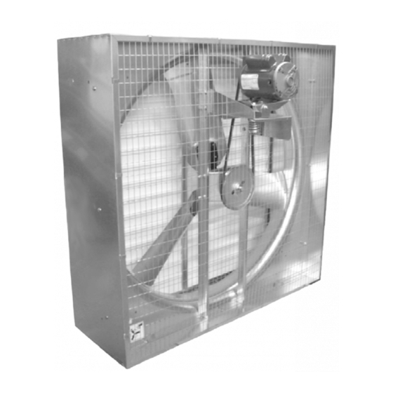
- Page 1 36" & 48" Shutter Box Fan Installation & Operator’s Instruction Manual Mv1666-021 01/01 Mv1666-005 12/00 October 2009 MV1666D...
-
Page 2: Chore-Time Warranty
QUALITY OF THE PRODUCT FURNISHED HEREUNDER. Chore-Time Distributors are not authorized to modify or extend the terms and conditions of this Warranty in any manner or to offer or grant any other warranties for Chore-Time products in addition to those terms expressly stated above. -
Page 3: Table Of Contents
Chore-Time Warranty ........ -
Page 4: General
Support Information The Chore-Time Shutter Fans are designed to be used as exhaust fans. The Shutter Fans are shipped unassembled to save on shipping charges. Using this equipment for any other purpose or in a way not within the operating recommendations specified in this manual will void the warranty and may cause personal injury. -
Page 5: About This Manual
36" & 48" Shutter Box Fan About This Manual About This Manual The intent of this manual is to help you in two ways. One is to follow step-by-step in the order of assembly of your product. The other way is for easy reference if you have questions in a particular area. -
Page 6: Follow Safety Instructions
Safety Information 36" & 48" Shutter Box Fan Safety Information Follow Safety Instructions Carefully read all safety messages in this manual and on your equipment safety signs. Follow recommended precautions and safe operating practices. Keep safety signs in good condition. Replace missing or damaged safety signs. Decal Descriptions DANGER: Electrical Hazard Disconnect electrical power before inspecting or servicing equipment unless... -
Page 7: Technical Information
ROTATING FAN BLADE) as shipped from the factory. Replace damaged or missing decals. Make sure the decals may be easily seen at all times. If the fan is purchased unassembled, the Chore-Time Fan Assembly Part Number Decal will be packed with this instruction manual. Make sure the decal location shown below is clean and dry. -
Page 8: Fan Assembly Procedure
Fan Assembly Procedure 36" & 48" Shutter Box Fan Fan Assembly Procedure For Factory Assembled Fans see Steps 3 through 6. Step 1 - Secure Motor Mount Post to Fan Shroud Secure the Motor Mount Post to the Fan Shroud using the 5/16-18 x 5/8'' carriage bolts and hex nuts provided in the Hardware Package The Motor Mount Post must be installed as shown in Figure 2. -
Page 9: Step 2 - Mount Side Panels To Fan Shroud
36" & 48" Shutter Box Fan Fan Assembly Procedure Step 2 - Mount Side Panels to Fan Shroud The Side Panels for the Box Fans are identical. The Panels lock together by inserting the tabs of one Panel into the slot in the end of another Panel (See Figure 3). Orienting the Side Panels as shown in Figure 3, assemble the Side Panels together around the Shroud using the 5/16-18 hardware provided. -
Page 10: Step 3A - (Direct Drive) Assembly Procedures
Fan Assembly Procedure 36" & 48" Shutter Box Fan Step 3A - (Direct Drive) Assembly Procedures Motor Assembly Item Description Motor Support Motor #10-32 Serrated Flange Nut Mv1666-010 01/01 Blade Assembly Item Description Blade Assembly Fan Blade Hub Motor Motor Shaft With Key/Keyway and Flat Mv1666-011 01/01 MV1666D... -
Page 11: Step 3B - (Belt Drive Assembly Procedures)
36" & 48" Shutter Box Fan Fan Assembly Procedure Step 3B - (Belt Drive Assembly Procedures) Motor Mount Assy. to Posts Note: The Shutter Fans may be ordered with or without the Motor. If a Factory Assembled Fan was ordered, the Fan Blade was shipped mounted to a Shipping Bracket. -
Page 12: Motor Sheave And Belt Installation
Fan Assembly Procedure 36" & 48" Shutter Box Fan Motor Sheave and Belt Installation Mount the Motor (Item 1, Figure 6) to the Pivot Motor Mount Plate (Item 3, Figure 6) by using the supplied 5/16-18 x .625'' Carriage Bolt (Item 10, Figure 6) with the heads coming up from the bottom and the 5/16-18'' Flange Nut (Item 11, Figure 6) on top. -
Page 13: Sheave Mounting
36" & 48" Shutter Box Fan Fan Assembly Procedure Sheave Mounting Apply Anti Seize to Motor Shaft (Item 3, Figure 7). Slide the Sheave onto the motor shaft as shown. Insert the key provided with the motor as shown in Figure 7. to lock the Sheave in place. -
Page 14: Belt Alignment
Fan Assembly Procedure 36" & 48" Shutter Box Fan Belt Alignment • Belt must be vertical to obtain maximum Belt Life. • Measure from a straight edge to the belt to make sure that there is equal dis- tance. (See Figure 8) IMPORTANT! Figure 8. -
Page 15: Fan Blade Installation
36" & 48" Shutter Box Fan Fan Assembly Procedure Fan Blade Installation Slide the Fan Blade Assembly onto the shaft. The Hub of the Fan Blade should be flush with the end of the Shaft (See Figure 9). Apply grease or an anti-seize compound to the Fan Shaft before mounting the Fan Blade. -
Page 16: Step 4 - Screen Installation
Fan Assembly Procedure 36" & 48" Shutter Box Fan Step 4 - Screen Installation DANGER! The Wire Inlet Screen MUST be installed to prevent serious injury or death. The Wire Inlet Screen has an opening to accommodate the Motor and Motor Mounting. -
Page 17: Step 5 - Shutter Louver Installation
36" & 48" Shutter Box Fan Fan Assembly Procedure Step 5 - Shutter Louver Installation Orient the Shutter Fan Assembly so that the drain holes are on the bottom. Insert the tab on the end of one of the Center Rails into the slot on the Bottom Side Panel. Slide the top of the Center Rail until it snaps into the corresponding slot in the Top Side Panel. -
Page 18: Shutter Louver Installation Continued
Fan Assembly Procedure 36" & 48" Shutter Box Fan Shutter Louver Installation Continued..Slide the next Shutter Louver on the opposite end of the Shutter Pivot Rod, Bend the Shutter Pivot Rod - Shutter Louver combination and insert the free end of the Shutter Pivot Rod into the second hole up from the bottom of the other Side Panel. -
Page 19: Fan Installation
36" & 48" Shutter Box Fan Fan Installation Fan Installation Build fan framing out of 2'' (50 mm) lumber (not supplied). The required wall opening is provided in the chart below. See Figure 16. Dimension (minimum) 36'' Fan 42-1/4'' 42-1/4'' [107.3 cm] [107.3 cm] 48'' Fan... -
Page 20: Maintenance
Add only a small amount of grease to purge impu- rities out of the bearing seals. Use only high quality lithium soap base grease and clean all dirt from zerk before applying grease. Chore-Time recommends using Shell Alvania # 2 in the fan shaft bear- ings. -
Page 21: Itemized Parts And Listing: 36" Dd Shutter Fan
36" & 48" Shutter Box Fan Itemized Parts and Listing: 36" DD Shutter Fan Itemized Parts and Listing: 36" DD Shutter Fan Mv1666-014 01/01 Part Item Qty. Description Number Motor Varies Bolt, Carriage 5/16-18 x .625 8282 5/16-18 Hex Ser. Flange Nut 8490 36"... -
Page 22: Parts Listing: 48" Bd Shutter Fan
Itemized Parts: 48" Belt Drive Shutter Fan Mv1666-012 01/01 3 28 32 33 3 28 3.84"... - Page 23 Part Numbers (48" Fans) Part Part Item Qty. Description Item Qty. Description Number Number Motor Varies Front Bearing Mount Plate 43689 Bolt, Carriage 5/16-18 x .625 8282 1" Bore Cast Flange Bearing 43654 5/16-18 Hex Ser. Flange Nut 8490 8-1/4" O.D 1" Bore Sheave 42072 48"...
- Page 24 Description of Change Various Updated Warranty page, Maintenance page, and added Third Party paragraph. Contact your nearby Chore-Time distributor or representative for additional parts and information. CTB Inc. P.O. Box 2000 • Milford, Indiana 46542-2000 • U.S.A. Phone (574) 658-4101 • Fax (877) 730-8825 E-Mail: ctb@ctbinc.com •...
Need help?
Do you have a question about the Mv1666-021 and is the answer not in the manual?
Questions and answers