Table of Contents
Advertisement
Quick Links
Thank You
The employees of CTB Inc. would like to thank you for your recent Chore-Time
purchase. If a problem should arise, your Chore-Time distributor can supply the necessary information
to help you.
Fan Part Numbers and Specifications
Fan Part No.
Bess Lab
Test No.
54659-21
13592
54659-21S
54659-22
13591
54659-22S
54659-41
13566
54659-41S
54659-42
13569
54659-42S
54659-51
13567
54659-51S
54659-52
13568
54659-52S
Operating static pressure should be less than 0.15 inches water column [37.5 Pa].
The fan inlet and exhaust must be kept clear of obstructions. Failure to keep the fan air-
flow path clear of obstructions could cause loss of fan performance and fan damage.
August 2018
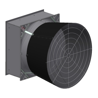
57" Endura
Installation & Operator's
Voltage
Phase
Hz
Nominal
RPM
230
1
60
537
230
1
60
538
230
3
60
532
230
3
60
536
230
3
50
526
230
3
50
532
Flush Mount Fan
®
Instruction Manual
Static Pressure at
Amps
Starting
CFM
Amps
3
[m
/hr]
7.1
36.0
29600
[50200]
5.6
27.5
26400
[44900]
4.9
40.0
29200
[49600]
4.2
40.0
26300
[44700]
5.3
45.0
28800
[49000]
4.7
45.0
26000
[44200]
Static Pressure
.10" w.c.
at .15" w.c.
[25 Pa]
[37.5 Pa]
CFM/W
CFM
CFM/W
3
3
[m
/hr/w]
[m
/hr]
[m
19.2
27300
[32.7]
[46400]
21.7
24300
[36.8]
[41200]
19.6
26800
[33.4]
[45600]
22.2
24200
[37.6]
[41000]
19.6
26500
[33.3]
[45000]
22
23700
[37.3]
[40300]
3
/hr/w]
16.8
[28.5]
18.8
[32.0]
17.1
[29.0]
19.2
[32.7]
17.1
[29.1]
18.9
[32.1]
MV2423F
Advertisement
Table of Contents

Subscribe to Our Youtube Channel
Related Manuals for Chore-Time Endura 57" Flush Mount Fan


Summary of Contents for Chore-Time Endura 57" Flush Mount Fan
- Page 1 Installation & Operator’s Instruction Manual Thank You The employees of CTB Inc. would like to thank you for your recent Chore-Time purchase. If a problem should arise, your Chore-Time distributor can supply the necessary information to help you. Fan Part Numbers and Specifications...
-
Page 2: Safety Information
Warranty ® CTB, Inc. ("CTB") warrants new CHORE-TIME ENDURA Fans ("Product") manufactured by CTB to be free from defects in material or workmanship under normal usage and conditions, for One (1) year from the date of installation by the original purchaser ("Warranty"). -
Page 3: Unassembled Fans Parts Packages
® 57" Endura Flush Mount Fan Installation & Operator’s Unassembled Fans Parts Packages Unassembled Fans Parts Packages Fan Blade Part No. (on Blade Spider) (53219-XX, 53532-XX, 54529-XX, or 54530-XX) (54671-XX) Fan Blade Package Component Package (53850-XX) Shroud and Door Package (53753-1, -2, -1S, -2S) (54661-AAXX, or -AAXXS) Drive Assembly... -
Page 4: Assembled Fans Parts Packages
Assembled Fans Parts Packages (54470) (54659-XXXP) (53129) Flush Mount Kit Fan Assembly 57" Fan Grill ® Assembled 57" Endura Fan Component Part Numbers Part Number 54659-21 54659-21S 54659-22 54659-22S 54659-41 54659-41S 54659-42 54659-42S 54659-51 54659-51S Fan Assembly 54659-21P 54659-21PS 54659-22P 54659-22PS 54659-41P 54659-41PS 54659-42P... -
Page 5: Hardware Needed Per Fan (Unassembled)
® 57" Endura Flush Mount Fan Installation & Operator’s Hardware Needed Per Fan (Unassembled) Hardware Needed Per Fan (Unassembled) ® 57" Endura Fan Hardware Items per Fan Items are bulk packed in 54661-AAXX, or 54661-AAXXS (See page 3). Item Qty. Description Part No. -
Page 6: Tools Needed And Supplies
® Tools Needed and Supplies 57" Endura Flush Mount Fan Installation & Operator’s Tools Needed and Supplies 3/8", 1/2", and 7/16" sockets or wrenches, side cutters, 1/4" nut driver, motor power cord, wire nuts / terminals, 5/32" allen wrench (un-assembled) New Installation Planning Fans can be installed with the Extension Box through the wall or outside the wall. -
Page 7: Installation
® 57" Endura Flush Mount Fan Installation & Operator’s Installation Spacing Planning the layout of the spacing between fans is very important. Spacing too close together will cause interference between the discharge cones. 60-1/16" [152.5cm] 72" [182.9cm] Recommended Spacing Minimum Spacing if sides of Cone are flattened 5"... - Page 8 ® Installation 57" Endura Flush Mount Fan Installation & Operator’s Step 2: Set the panels in the framed opening as shown. Identify the 54469-1 Left Side Panel with wider flange extending up. Wider Flange Flange Identifies Top Panel Top Panel (54467) Install with Screen Clips toward the inside ofthe building.
- Page 9 ® 57" Endura Flush Mount Fan Installation & Operator’s Installation Step 4: Orient the Screen with the notched corner top right and snap the Screen into the Screen Clips a shown. notched corner of Screen Screen Clips Step 5: With the Screen In place attach the Panels Step 6: Remove the Screen and finish fastening with 1/4-10 x 1-1/2"...
-
Page 10: Fan Shroud Assembly (Unassembled Version)
® Fan Shroud Assembly (Unassembled version) 57" Endura Flush Mount Fan Installation & Operator’s Inspecting the Shroud (For assembled versions skip to pg. 15) Inspect the Shroud Assembly for hardware as it is received (53626) Center V-Post (53398) Cross Rod (48427) Magnet (7791-3) -
Page 11: Attaching Fan Posts
Attaching Fan Posts Decal (46764) x3 (46764) x3 (53204) (53204) Fan Post (53039) Cone Bracket (53039) Cone Bracket (53205) Top Corner (53206) Bottom Corner Support Bracket Support Bracket 2nd Hole 1st Hole Two Notches View from Front of Fan One Notch (bottom left corner) Hardware (54287) x3... -
Page 12: Cone Brackets, Corner Brackets (Corners Without Posts)
Cone Brackets, Corner Brackets (Corners without Posts) (46764) (46764) (53206) Bottom (53205) Corner Brkt. Top Corner Support Bracket (54287) Bolt (54287) (53039) Cone Bracket (53039) Cone Bracket 1st Hole One Notch Two Notches Hardware Full Scale (46764) 5/16 Flg. Nut (54287) 5/16-18 x 1.00 SS Shldr. -
Page 13: Installing The Drive Assembly And Motor Mount
® 57" Endura Flush Mount Fan Installation & Operator’s Fan Shroud Assembly (Unassembled version) Installing the Drive Assembly and Motor Mount Apply a Fan Description Decal to the Shroud as shown. (Included in Parts Package) (48396C) Motor Support (46764) (53753-X) Drive Assembly (46764) (54287) x8... -
Page 14: Top And Bottom Pivot Plates And Eyebolt, Door Stop Cable
® Fan Shroud Assembly (Unassembled version) 57" Endura Flush Mount Fan Installation & Operator’s Top and Bottom Pivot Plates and Eyebolt, Door Stop Cable (53037) (46764) Top Pivot V-Post (46764) Pivot Plate Tab Centered in V-Post (3066) Eyebolt (53036) Bottom Pivot Plate Pivot Plate Tab V-Post Centered in V-Post... - Page 15 ® 57" Endura Flush Mount Fan Installation & Operator’s Fan Shroud Assembly (Unassembled version) Attaching the Fan to the Extension Housing (shown with doors removed) Step 1: Set the Fan on the Bottom Panel Shelf as shown. Eyebolt indicates the top of the Fan Shelf Step 2: Attach the Shroud to the Extension Box Panels with 1/4-20 x 7/8"...
-
Page 16: Cone Assembly
® Fan Shroud Assembly (Unassembled version) 57" Endura Flush Mount Fan Installation & Operator’s Cone Assembly Assemble Cone Panels as shown below. Prop the Cone Panels up off the ground to ease assembly one hole Two Holes tabs Up tabs Snap positively in place. -
Page 17: Installing The Orifice Frame
® 57" Endura Flush Mount Fan Installation & Operator’s Fan Shroud Assembly (Unassembled version) Installing the Orifice Frame Rounded Tab on the Cone Important! Line up the seam in the Orifice Frame with one of the rounded tabs on the Cone. (46764) (53611) Frame Bracket... - Page 18 ® Fan Shroud Assembly (Unassembled version) 57" Endura Flush Mount Fan Installation & Operator’s Hang the Cone on the Eye-Bolt extruding from the top of the Shroud using the hole in the Cone as shown. (30663) Eyebolt Seam in Orifice Frame MV2423F...
- Page 19 ® 57" Endura Flush Mount Fan Installation & Operator’s Fan Shroud Assembly (Unassembled version) Attach the cone to the Shroud as shown below. Slip the Orifice Frame behind the Bottom Pivot Plate. Bottom Pivot Plate 5/16 Flg. Nut (46764) If necessary, slip a thin piece of metal between the Shroud and Cone and work it around the Cone to get it on.
-
Page 20: Door Assembly And Installation
® Fan Shroud Assembly (Unassembled version) 57" Endura Flush Mount Fan Installation & Operator’s Door Assembly and Installation Doors are Left and Right specific. Insert Door Pins in both Doors as shown. Push Pins in until they bottom out. (53038) Door Pin View of back of Door View of back of Door Door... -
Page 21: Grill Installation
® 57" Endura Flush Mount Fan Installation & Operator’s Fan Shroud Assembly (Unassembled version) Grill Installation Install the Fan Cone Grill (as shown). Attach the end of the Door Stop Cable to the bottom Grill leg as shown. (54287) (46764) (ST99070) Door Stop Cable... -
Page 22: Rotate Motor Support (Assembled Fans)
Rotate Motor Support (Assembled Fans) Attach the Motor Support Bracket to the Posts with Rotate the Motor Support Bracket into the upright position by removing the 5/16 Bolts (54287) and 5/16 Flange Nuts (46764). upper Bolt and Nut, and loosening the lower Bolt and Nut. Remove Bolt Loosen Bolt 4x (54287) 5/16-18 x 1.00... -
Page 23: Motor Installation
® 57" Endura Flush Mount Fan Installation & Operator’s Fan Shroud Assembly (Unassembled version) Motor Installation Attach Motor to Z-Bracket. (54287) Motor Z-Bracket (46764) Torque Set Screw to 150-165 IN-LBS [16.9-18.6 NM] Motor Anti-Seize Motor Sheave 3/16" Key Supplied (Taped to Motor) Center the Sheave with the Hole in the Z-Bracket... -
Page 24: Belt Installation
® Fan Shroud Assembly (Unassembled version) 57" Endura Flush Mount Fan Installation & Operator’s Belt Installation Motor Sheave Fan Blade Tensioner Pulley Push Part Number Belt Driven Sheave Blade Installation (Unassembled Fans) Anti-Seize Blade 1/4" Key Torque Blade Set Screws Fan Blade Flush to 150-160 IN LBS. -
Page 25: Door Spring Installation (Unassembled Versions)
® 57" Endura Flush Mount Fan Installation & Operator’s Fan Shroud Assembly (Unassembled version) Checking Fan Blade Tip Clearance Spin the Blade by hand and check that there is minimum of 1/8" [3 mm] clearance from the Shroud all the way around orifice. Door Spring Installation (Unassembled versions) Door Springs Elongated end of Spring... -
Page 26: Motor Wiring
® Fan Shroud Assembly (Unassembled version) 57" Endura Flush Mount Fan Installation & Operator’s Motor Wiring (54683) 1/4-20 x 1/2 Check that the electrical power (565) Cord Clip Self Tapping Screw being supplied to the Fan matches the electrical Specifica- tions on the Fan and Motor Decals. -
Page 27: Screen Installation
® 57" Endura Flush Mount Fan Installation & Operator’s Screen Installation Screen Installation Attach the Screen as shown. Orient the Screen so the notched corner is upper right for Cord Routing. Screen Corner notched out for Cord Routing (54464) Screen Snap Screen into Screen Clips MV2423F... -
Page 28: Test Fan For Proper Operation
® Test Fan for proper operation. 57" Endura Flush Mount Fan Installation & Operator’s Test Fan for proper operation. Plug the Fan in and test for proper operation Maintenance IMPORTANT! Disconnect Power Prior To Maintaining Or Cleaning The Fan. The fan may start automatically causing serious injury or death. -
Page 29: Fan Bearing And Belt Tensioner Lubrication
® 57" Endura Flush Mount Fan Installation & Operator’s Maintenance Fan Bearing and Belt Tensioner Lubrication • Grease zerks are provided for lubrication on the fan shaft bearings and the belt tensioner. • Lubricate the fan every 2-6 months or whenever these components get wet. •... -
Page 30: Part Numbers (Itemized)
Part Numbers (Itemized) Two Notches 17 x4 Detail "B" Detail "A" 20x 62 32 x4 One Notch 31 x4 Detail "B"... -
Page 31: Part Numbers
Part Numbers Item Qty. Description Part No. Models 57" Galv. High Cap. Fan Blade 53219 -21,-41,-51 57" Galv. E. Efficiency Fan Blade 53532 -22,-42,-52 57" High Capacity SS Fan Blade 54529 -21S,-41S,-51S 57" E. Efficiency SS Fan Blade 54530 -22S,-42S,-52S 1/4"... - Page 32 Part Numbers Itemized (Continued) 20 x4...
- Page 33 Part Numbers (Continued) ® 57" Endura Fan Part Numbers 54659-XX, or 54659-XX,XXS Item Qty. Description Part No. Models Orifice Frame 53416 Orifice Frame Bracket 53611 57" Cone Panel 53163 Top Pivot Plate 53037 Bottom Pivot Plate 53036 Ø1/2" x 11" Door Spring 49629 3/32"...
-
Page 34: Revisions To This Manual
Updated Contact Info 30,31 Item 49 was 53896 Added Pivot Plate Tab Detail For additional parts and information, contact your nearest Chore-Time distributor or representative. Find your nearest distributor at: www.choretime.com/contacts Chore-Time Group, A division of CTB, Inc. PO Box 2000...
Need help?
Do you have a question about the Endura 57" Flush Mount Fan and is the answer not in the manual?
Questions and answers