Chore-Time TURBO Installation & Operator's Instruction Manual
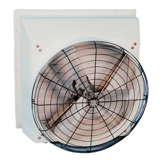
36" belt drive fiberglass cone and grill fans
Hide thumbs
Also See for TURBO:
- Installation & operator's instruction manual (16 pages) ,
- Installation manual (12 pages) ,
- Installation & operator's instruction manual (16 pages)
Table of Contents
Advertisement
Quick Links
Download this manual
See also:
Installation Manual
Advertisement
Table of Contents

Related Manuals for Chore-Time TURBO


Summary of Contents for Chore-Time TURBO
- Page 1 TURBO Fiberglass Cone and Grill Fans ® 36" Belt Drive Installation & Operator’s Instruction Manual Mv1680-001 02/01 Mv1680-002 02/01 October 2017 MV1680H...
-
Page 2: Chore-Time Extended Warranty
If such a defect is found by Chore-Time to exist within the applicable period, Chore-Time will, at its option, (a) repair or replace such product free of charge, F.O.B. the factory of manufacture, or (b) refund to the original purchaser the original purchase price, in lieu of such repair or replacement. -
Page 3: Table Of Contents
Chore-Time Extended Warranty ........ -
Page 4: General
Contents also specifies which pages contain information for the sales personnel, installer, and consumer (end user). Important! Chore-Time Equipment strongly recommends that a good alarm system should be installed in confinement buildings to warn of power failure and high temperature. Chore-time Equipment also recommends that an alternate power source be available for confinement buildings in case of power failure. -
Page 5: About This Manual
36" Belt Drive About This Manual About This Manual The intent of this manual is to help you in two ways. One is to follow step-by-step in the order of assembly of your product. The other way is for easy reference if you have questions in a particular area. -
Page 6: Follow Safety Instructions
Safety Information 36" Belt Drive Follow Safety Instructions Carefully read all safety messages in this manual and on your equipment safety signs. Follow recommended precautions and safe operating practices. Keep safety signs in good condition. Replace missing or damaged safety signs. Decal Descriptions DANGER : Electrical Hazard Disconnect electrical power before inspecting or servicing equipment unless... -
Page 7: Decal Location
Planning the Installation Carefully plan the installation. ® Dimensions are provided for the 36" TURBO Fans with Cones (Figure 1) and without Cones (Figure 2). Be sure to allow enough space to install fans without interfering with other fans or equipment that may be installed at a later date. -
Page 8: Planning The Installation Continued
Fan Installation 36" Belt Drive Planning the Installation Continued..Mv1680-009 02/01 Rough Frame Minimum Opening 45.38" 43.00" 0" 27" (115.27 cm) (109.22 cm) (0.00 cm) (68.58 cm) Figure 2. Planning and Layout Diagram for Grill Fans Installing the Fan to the Framed Opening 1. -
Page 9: Installing The Cone Or Grill To The Fiberglass Fan
36" Belt Drive Fan Installation 3. Insert the Fan Assembly in the wall opening and secure using the (12) 1/4 x 1-3/4 Lag Screws, Shutter Clips, and Nylon Washers provided. The Shroud is pre-drilled (3 holes per side).The hardware must be installed as shown in Figure 4 below. -
Page 10: Fiberglass Grill Fan
Fan Installation 36" Belt Drive Fiberglass Grill Fan: 1. Align the holes in the Grill with the slots in the Shroud. 2. Insert the (6) Wafer Head Bolts from inside the Shroud through the Grill and thread the Flange Nuts onto the ends of the Wafer Head Bolts. Description Part No. -
Page 11: Remove Nylon Ties
36" Belt Drive Fan Installation Remove Nylon Ties 1. Cut and Remove Nylon Ties from the Driven Sheave and the Motor (See Figure 7). Nylon Tie Figure 7. Removing Nylon Tie’s Installing the Belt and Tension Spring 1. Install the Belt as shown. Install the Tension Spring in the 5th notch from the top (See Figure 8). -
Page 12: Shutter Installation
Fan Installation 36" Belt Drive Shutter Installation Plastic and Aluminum Shutters are available for the 36" Fans. Installation is identical except where noted. See below. 1. If you have a Plastic Shutter—cut a 3/8" slot in the upper left flange of the Shutter frame in order to route the electrical cord out the back. -
Page 13: Shutter Installation Continued
36" Belt Drive Motor Specifications and Drive Component Part Numbers Shutter Installation Continued..Plastic Shutter Part Numbers Item Description Part No. Shutter Assembly 38027 (White) Plastic Shutter Assembly 46972 (Gray) Plastic Push Nut, 1/4" 38032 Shutter Rod Pivot 38702-2 MV1680-014 04/02 Shutter Louver (White) 38038-2 Shutter Louver (Gray) 46715-2... -
Page 14: Maintenance
Maintenance 36" Belt Drive Maintenance Service and maintenance of fans should be done only by a qualified technician. Disconnect Power prior to maintaining or cleaning the fan! The fan may start automatically causing injury or death. 1. Keep the fan clean for maximum life and performance. 2. - Page 15 36" Belt Drive Maintenance This page left blank intentionally..MV1680H...
-
Page 16: Belt Drive Turbo® Fan Parts List
® Belt Drive TURBO Fan Parts List 31 32 33 15 27 Mv1680-006 02/01... -
Page 17: Belt Drive Turbo Part Numbers
® Belt Drive TURBO Part Numbers Item Qty. Description Part No. Item Qty. Description Part No. Motor Varies* 1" Cast Pillow Block Bearing 50553 5/16-18x.75 SS Carr. Bolt 27868-1 1/4 x 1-1/8 Sq. Key 2419-2 Upper Motor Mount Support 37735... - Page 18 Description of Change Added Wire tie removal and Belt and Spring installation 33242 Contact your nearby Chore-Time distributor or representative for additional parts and information. CTB Inc. P.O. Box 2000 • Milford, Indiana 46542-2000 • U.S.A. Phone (574) 658-4101 • Fax (877) 730-8825 E-Mail: ctb@ctbinc.com •...
Need help?
Do you have a question about the TURBO and is the answer not in the manual?
Questions and answers