
Subscribe to Our Youtube Channel
Related Manuals for Chore-Time MV1666B


Summary of Contents for Chore-Time MV1666B
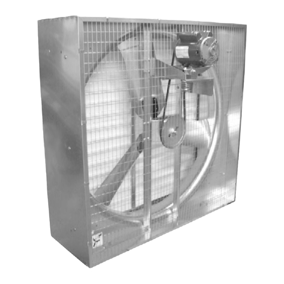
- Page 1 36" & 48" Shutter Box Fan Installation & Operator’s Instruction Manual Mv1666-005 12/00 February 2004 MV1666B...
-
Page 2: Chore-Time Warranty
QUALITY OF THE PRODUCT FURNISHED HEREUNDER. Chore-Time Distributors are not authorized to modify or extend the terms and conditions of this Warranty in any manner or to offer or grant any other warranties for Chore-Time products in addition to those terms expressly stated above. -
Page 3: Table Of Contents
Chore-Time Warranty ........ -
Page 4: General
Support Information The Chore-Time Shutter Fans are designed to be used as exhaust fans. The Shutter Fans are shipped unassembled to save on shipping charges. Using this equipment for any other purpose or in a way not within the operating recommendations specified in this manual will void the warranty and may cause personal injury. -
Page 5: About This Manual
WARNING indicates a potentially hazardous situation which, if not avoided, COULD result in death or serious injury. CAUTION indicates a hazardous situation which, if not avoided, MAY result in minor or moderate injury. MV1666B... -
Page 6: Follow Safety Instructions
With the exception of motor overload protection, electrical disconnects and over current protection are not supplied with the equipment. DANGER: Rotating Fan Blade This decal is placed on the Panel Weldment. Severe personal injury will result, if the electrical power is not disconnected, prior to servicing the equipment. MV1666B... -
Page 7: Technical Information
ROTATING FAN BLADE) as shipped from the factory. Replace damaged or missing decals. Make sure the decals may be easily seen at all times. If the fan is purchased unassembled, the Chore-Time Fan Assembly Part Number Decal will be packed with this instruction manual. Make sure the decal location shown below is clean and dry. -
Page 8: Fan Assembly Procedure
Hardware Package The Motor Mount Post must be installed as shown in Figure 2. 36" 48" Description Fan Shroud Motor Mount Post 5/16-18 x 5/8'' Carriage Bolt 5/16-18 Serrated Nut Mv1666-002 12/00 Figure 2. Motor Mount Installation MV1666B... -
Page 9: Step 2 - Mount Side Panels To Fan Shroud
Mv1666-003 12/00 Item Description Item Description Side Panel Lock Side Panels together by bending tabs over. Fan Shroud Shroud Drain Holes 5/16-18 x 5/8'' Carriage Bolt Shroud Orifice 5/16-18 Serrated Nut Knockouts Figure 3. Mounting Side Panels to shroud MV1666B... -
Page 10: Step 3A - (Direct Drive) Assembly Procedures
36" & 48" Shutter Box Fan Step 3A - (Direct Drive) Assembly Procedures Motor Assembly Item Description Motor Support Motor #10-32 Serrated Flange Nut Mv1666-010 01/01 Blade Assembly Item Description Blade Assembly Fan Blade Hub Motor Motor Shaft With Key/Keyway and Flat Mv1666-011 01/01 MV1666B... -
Page 11: Step 3B - (Belt Drive Assembly Procedures)
The Motor is mounted in the rear set of holes. Description Part 5/16''-18 Hex Serr. Flange Nut 8490 5/16''-18 Carriage Bolt 8282 Module Assembly 45581 Motor Mount Assembly (BD) 45698 Motor Support Post 43688 Mv1666-004 12/00 Figure 5. Fan Module and Motor Installation MV1666B... -
Page 12: Motor Sheave And Belt Installation
Pivot Plate Mounting Bracket 43714 Z-Motor Mounting Bracket 43712 Bolt, 5/16-18 x 5.5'' 4412-21 Spring Cap (2 pcs) 44002 5/16'' Flange Nut 2148 5/16'' Flat Washer 5/16-18 x .625'' Carriage Bolt 8282 5/16-18" Flange Nut 8490 Figure 6. Motor Installation MV1666B... -
Page 13: Sheave Mounting
Sheave in place. Once the belt has been aligned, torque the set screw to 150-165 in-lbs to secure Sheave in place. (Do not tighten set screw until the belt is aligned.) MV1601-008 11/00 Item Description Sheave Anti-Seize Figure 7. Sheave Mounting and Key Assembly. MV1666B... -
Page 14: Belt Alignment
Mv1666-020 01/01 Belt Alignment Item Description Spring Compression to 2-1/4''. Install Belt as shown. Straight edge Measure from straight edge to belt. Frame to belt measurement to be the same at motor and driven sheaves. Figure 8. Belt Alignment MV1666B... -
Page 15: Fan Blade Installation
If Decals are not already installed, see the Decal placement instructions on page 7. Item Description Blade Assembly Torque to 150 in/lbs (12.5 ft/lbs) Shaft with Keyway Fan Blade Hub Flush with Shaft Mv1666-009 12/00 Figure 9. Blade Assembly Installation MV1666B... -
Page 16: Step 4 - Screen Installation
See Figure 11. MV1544-3B 8/99 Item Description Screen Clip Part Number 38891 Wire Screen Part Numbers (36") 36629, and (48") 45865 Slip Screen Clip over Screen Wire. Snap in slot on Fan Side Panel to secure. Figure 11. Screen Installation MV1666B... -
Page 17: Step 5 - Shutter Louver Installation
Shutter Louver, and into the second hole up from the bottom on the Side Panel. (See Figure 13) Item Description Side Panel Shutter Louver Center Rails Bottom Side Panel Shutter Pivot Rod Mv1666-008 01/01 Figure 13. Installing the first Shutter Louver MV1666B... -
Page 18: Shutter Louver Installation Continued
Top 36'' Shutter Fan Mount 44402 Top 36'' Shutter Fan Mount 44400 Side 36'' Shutter Fan Mount 44403 Side 36'' Shutter Fan Mount 44401 Mounting Kit Package Hardware 44506 Mounting Kit Package Hardware 44507 Figure 15. Optional Mounting Kit MV1666B... -
Page 19: Fan Installation
Fan Shaft Bearings when relubrication is needed. Relubrication is required whenever water comes in contact with the Fan Shaft Bearings. Slowly rotate the Fan Shaft as bearing is filled with Grease. Use only high quality lithium soap base grease and clean all dirt from Zerk before applying grease. MV1666B... -
Page 20: Shutter Fan Specification
36" Direct Drive 44453-3620 115/230 28936 Shutter Fans 44453-3640 208-230/460 42098 41134-4820 40921-4820 37729 35333 48" Belt Drive 41134-4830 40921-4830 37729 8773 Shutter Fans 41134-4840 40921-4840 208-230/460 40157 35333 41134-4850 40921-4850 220-240/380-415 36142 24697 41134-4860 40921-4860 230/380-415 36142 35333 MV1666B... -
Page 21: Itemized Parts And Listing: 36" Dd Shutter Fan
36" DD Fan Motor Support 36564 Danger Decal 2527-50 EZ DD Shutter Fan Decal 39002-208 Screen Clip 38891 40" x 40" Wire Inlet Screen 36629 36" Fan Shutter Rail 40706 36" Shutter Louver 38038-11 *See Shutter Fan Specifications Page 20. MV1666B... -
Page 22: Parts Listing: 48" Bd Shutter Fan
Parts Listing: 48" BD Shutter Fan Part Part Item Qty. Description Item Qty. Description Number Number Motor Varies Front Bearing Mount Plate 43689 Bolt, Carriage 5/16-18 x .625 8282 1" Bore Cast Flange Bearing 43654 5/16-18 Hex Ser. Flange Nut 8490 8-1/4"... -
Page 23: Itemized Parts: 48" Belt Drive Shutter Fan
Itemized Parts: 48" Belt Drive Shutter Fan Mv1666-012 01/01 3 28 32 33 3 28 3.84"... - Page 24 Description of Change Various Replaced 305 washer and 4297 nut with 48113 Serrated Flange Nut on 36 DD Fans Contact your nearby Chore-Time distributor or representative for additional parts and information. CTB Inc. P.O. Box 2000 • Milford, Indiana 46542-2000 • U.S.A.
Need help?
Do you have a question about the MV1666B and is the answer not in the manual?
Questions and answers