
Related Manuals for Chore-Time MV1430J


Summary of Contents for Chore-Time MV1430J
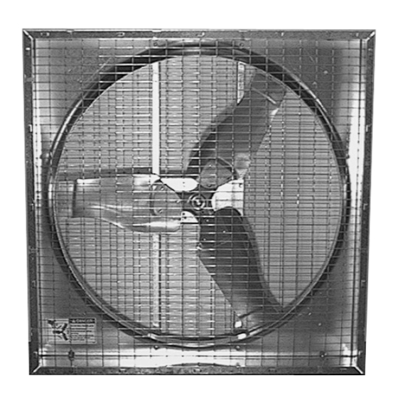
- Page 1 36” & 48” E-Z Box Fan Installation & Operator’s Instruction Manual (Direct Drive · Standard & Deep Box) April 2018 MV1430J...
-
Page 2: Chore-Time Warranty
One (1) year from the date of installation by the original purchaser (“Warranty”). If such a defect is determined by Chore-Time to exist within the applicable period, Chore-Time will, at its option, (a) repair the Product or Component Part free of charge, F.O.B. the factory of manufacture or (b) replace the Product or Component Part free of charge, F.O.B. -
Page 3: Table Of Contents
Chore-Time Warranty ........ -
Page 4: Support Information
Chore-Time 36” & 48” Direct Drive E-Z Box Fan Manual Support Information The Chore-Time E-Z Fans are designed to be used as circulating or exhaust fans. The E-Z Fans may be shipped unassembled to save on shipping charges. Using this equipment for any other purpose or in a way not within the operating recommendations specified in this manual will void the warranty and may cause personal injury. -
Page 5: Safety Information
Chore-Time 36” & 48” Direct Drive E-Z Box Fan Manual Safety Information Caution, Warning and Danger Decals have been placed on the equipment to warn of potentially dangerous situations. Care should be taken to keep this information intact and easy to read at all times. -
Page 6: Technical Information
ROTATING FAN BLADE) as shipped from the factory. Replace damaged or missing decals. Make sure the decals may be easily seen at all times. If the fan is purchased unassembled, the Chore-Time Fan Assembly Part Number Decal will be packed with this instruction manual. Make sure the decal location shown below is clean and dry. -
Page 7: Tools Required
Chore-Time 36” & 48” Direct Drive E-Z Box Fan Manual Tools Required • Regular Screwdriver • Hammer • 1/2” Open End Wrench or Socket Wrench with 1/2” Socket • Wire Cutters & Strippers • Adequate Size & Quantity of Electrical Wire •... - Page 8 Chore-Time 36” & 48” Direct Drive E-Z Box Fan Manual The Side Panels for the Box Fans are identical. The Panels lock together by inserting the tabs of one Panel into the slot in the end of another Panel. See the detail in Figure 2.
- Page 9 Chore-Time 36” & 48” Direct Drive E-Z Box Fan Manual MV1430-050 2/04 Figure 3. Motor Installation (side view) Description Motor Support Motor 10-32 Serrated Flange Nut 48” Fan Figure 4. Motor Installation (side view) Description Motor Support Motor 3/8” x 3/4” Bolt Lock Washer Slide the Blade Assembly onto the motor shaft.
- Page 10 Chore-Time 36” & 48” Direct Drive E-Z Box Fan Manual Apply Anti-seize (47749) to motor shaft. Insert key into keyway on motor shaft. Tighten the set screw(s) using a 5/16” open end wrench (12 point 3/8” socket and ratchet). Torque the set screws to approximately 150 in./lbs.
- Page 11 Chore-Time 36” & 48” Direct Drive E-Z Box Fan Manual DANGER: Wire Screen(s) MUST be installed to prevent serious injury or death. Position the front Screen over the front of the fan. Note: Make sure the natural bow of the Screen is away from the fan (to avoid blade interference).
-
Page 12: Slant Wall Kit Assembly (Optional)
Chore-Time 36” & 48” Direct Drive E-Z Box Fan Manual Slant Wall Kit Assembly (Optional) If the Fan Assembly is to be installed in a side wall, the E-Z Fan Slant Wall Housing Kit may be assembled and installed. Refer to Figure 7 for assembly information. -
Page 13: Fan Installation
Chore-Time 36” & 48” Direct Drive E-Z Box Fan Manual Figure 8. Slant Wall Lock Tab Description Screwdriver Box Fan Panel Slant Wall Panel Fan Installation The E-Z Fan may be installed in a wall or suspended from the ceiling. For installations with the fan suspended from the ceiling, refer to Figure 12. -
Page 14: Fan Assembly With Slant Wall Housing
Chore-Time 36” & 48” Direct Drive E-Z Box Fan Manual Fan Assembly with Slant Wall Housing: Insert the Fan Assembly and Slant Wall Housing through the framed opening in the side wall. Center the Slant Wall Housing in the framed opening, left to right. Allow the Slant Wall Housing to set on the bottom of the framed opening. -
Page 15: Suspended Fan Installations
Chore-Time 36” & 48” Direct Drive E-Z Box Fan Manual Suspended Fan Installations: Replace Items 9 - 11 from both sides of the top of the fan with the suspension components, Items 1 - 7, as shown in Figure 12. Discard Items 9 - 11. -
Page 16: Wiring
Chore-Time 36” & 48” Direct Drive E-Z Box Fan Manual Wiring: See wiring diagram on Motor for Motor electrical connections. Follow local, state and national electric codes for wiring. Install an electric disconnect within reach of each Fan. Slant Wall Fans: Route the motor cord (not supplied) toward the upper left corner of fan and attach the cord to the top panel using the 3/8”... -
Page 17: Shutter Installation
Chore-Time 36” & 48” Direct Drive E-Z Box Fan Manual Shutter Installation Install the Grommet in the corner of the Aluminum Shutter only. See Figure 14. For fans with plastic shutters, cut a 3/8” slot in the left end of the top flange of the shutter to route the cord through when the shutter is installed. -
Page 18: Direct Drive E-Z Fan Part Numbers And Motor Specifications
Chore-Time 36” & 48” Direct Drive E-Z Box Fan Manual Direct Drive E-Z Fan Part Numbers and Motor Specifications Direct Drive E-Z Box Fans Assembled Unassembled Electrical Specs. Fan Description Fans Fans Fan P/N + Fan P/N + Voltage Phase... -
Page 19: Direct Drive E-Z Fan Parts List
Chore-Time 36” & 48” Direct Drive E-Z Box Fan Manual Direct Drive E-Z Fan Parts List 36” Fans 48” Fans Item Description Part No. Item Description Part No. 36” Fan Shroud 5538 48” Fan Shroud 37583 Motor Mount Post 37209... - Page 20 Revisions to this Manual Page No. Description of Change Change part number from 28936 to 56061 33445 Contact your nearby Chore-Time distributor or representative for additional parts and information. Chore-Time Group A division of CTB, Inc. PO Box 2000 Milford, Indiana 46542-2000 USA Phone (574) 658-4101 Fax (877) 730-8825 E-mail: poultry@choretime.com...
Need help?
Do you have a question about the MV1430J and is the answer not in the manual?
Questions and answers