Table of Contents
Advertisement
Quick Links
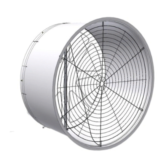
52" TURBO
Installation & Operator's Instruction Manual
Fan Type
Fan Assembly
Part No.
Standard
49740-22*
High Capacity
49740-21*
Standard
49740-42*
High Capacity
49740-41*
High Capacity
49740-51*
*Part Numbers shown are for White Fans with White Cones. Add a "B" to the Part Number example: "49740-22B" for a Black Fan w/ Black
Cone, Add a "BW" for a Black Fan w/ White Cone.
August 2017
Fan with HYFLO
®
Sub Assembly
Bess Lab
Part No.
Test No.
49862-22
04334
49862-21
04312
49862-42
04335
49862-41
04318
49862-51
Voltage
Hz
Ph HP
230
60
1
230
60
1
208-230/460
60
3
208-230/460
60
3
200-380/415
50
3
Door
®
Fan
cfm @
rpm
.10" w.c.
1.5
564
24900
1.5
611
27700
1.5
566
24800
1.5
615
27900
1.5
MV1864P
cfm/Watt
.10" w.c.
20.8
18.3
20.5
18.2
Advertisement
Table of Contents

Related Manuals for Chore-Time TURBO MV1864P


Summary of Contents for Chore-Time TURBO MV1864P
- Page 1 52" TURBO Fan with HYFLO Door ® ® Installation & Operator’s Instruction Manual Fan Type Fan Assembly Sub Assembly Bess Lab Voltage Ph HP cfm @ cfm/Watt Part No. Part No. Test No. .10" w.c. .10" w.c. Standard 49740-22* 49862-22 04334 24900 20.8...
- Page 2 Fan and Fan Framing Dimensions Fan and Fan Framing Dimensions Item Description 59” [149.86 cm] 67.81" [172.2 cm] 53” [134.91 cm] 7.5" [19.1 cm] 59" [149.86 cm] 8.3 [21.11 cm] Figure 1. Fan and Framing Dimensions Planning the layout of the spacing between fans is very important. A Minimum of 13" between Fan rough openings is required so the Cones do not interfere.
-
Page 3: Installation
Installation Installation Fan Mounting Insert the Fan Assembly in the wall opening. Rotate the Fan Blade by hand and check to make sure that there is a minimum of 1/8" Blade clearance all the way around the Shroud orifice. Shift the Fan around in the wall opening, if needed, to achieve at least 1/8"... - Page 4 Installation Locate the three holes across the top Fan Shroud flange (Item 5, Figure 3). Line up the Screen Retainers included in the Parts Package (Item 1, Figure 3) with these three holes, slip them over the top Fan Shroud flange, and using (3) 1/4 x 1-3/4 Lag Screws included in the Parts Package attach the Fan to the Wall (Step 1, Figure 3).
-
Page 5: Removing The Doors
Installation Removing the Doors To avoid damaging the Fan Doors it is best to remove them before attaching the Cone. Unhook the Door Springs from the Door and leave them attached to the Fan so they are not lost (Figure 4, Step 1). Remove the Door Clip and Washer and open up the Doors (Step 2). - Page 6 Installation Attaching the Cone To install the Cone you must first identify the Top of the Cone. The cutout in the top of the Cone does not extend out to the Cones edge (See Figure 5). Begin Installing the Cone by hooking the top of the Cone over the top of the Fan orifice.
-
Page 7: Replacing The Doors
Installation Finish attaching the Cone to the Fan Shroud with (4) 1/4-20 x 7/8 Bolts and Flange Nuts in the (4) remaining holes pre-drilled in the Cone (Figure 7 below). Description Cone Shroud 1/4-20 x 7/8 SS HH Bolt (Included in Parts Pkg.) 1/4-20 HX Serrated Flange Nut... - Page 8 Installation Attaching the Nylon Cable Remove the Nylon Cable (Item 1, Step 1) from the parts package and insert it into the hole in the Top Pivot Bracket (Item 2) as shown. Insert the other end of the Nylon Cable into the Cable Bracket (Item 3, Step 2) included in the parts package leaving approximately 1"...
- Page 9 Installation Attaching the Grill Attach the Grill to the Cone by inserting the Grill ends into the slots in the Cone as shown in Figure 10 below. Description Cone Grill End Figure 10. Attaching Grill MV1864P...
-
Page 10: Installing The Screen
Installation Installing the Screen Orient the Screen as shown below with the fine mesh section on the outside of the Fan. Slide the top of the Screen under the Screen Retainers (Step 1, Figure 11) and turn the bottom Screen Clip to hold the Screen in place (Step 2). - Page 11 Wiring Wiring 1. See Wiring diagram on Motor for Motor electrical connections. Follow local, state, and national electrical codes for wiring 2. Install an electrical disconnect within reach of each Fan. 3. Route the motor cord (not supplied) toward the upper left corner of the Fan and attach the cord to the Motor Mount using the Cable Tie—included in the hardware package.
-
Page 12: Maintenance
Maintenance Maintenance •Disconnect Power Prior To Maintaining Or Cleaning The Fan. The fan may start automatically causing serious injury or death. • Service and repair of fans should be done only by a qualified technician. • Keep the Fan clean for maximum life and best performance. Do Not spray water on Fan Shaft Bearings, Belt Tensioner, or the Motor. - Page 13 (BD) 208-230/460 V, 60 HZ, 3PH, 1.5 HP 208-230/460 V, 60 HZ, 3PH, 1.5 HP C H OR E-TIME EQU IPMEN T MILFOR D , IN 46542 39002-450 CHORE-TIME EQUIPMENT 39002-450 MILFORD, IN 46542 Belt Outside Wheel Inside Wheel Fan Part No.
-
Page 14: Part Numbers
200-230/460 V, 60 HZ, 3 PH, 1.5 HP CHORE-TIM E EQUIPMENT MILFORD, IN 46542 39002-452 See Detail Next Page Fan Part No. 49862-41 52" TURBO ® HYFLO ® 200-230/460 V, 60 HZ, 3 PH, 1.5 HP CHORE-TIME EQUIPMENT MILFORD, IN 46542 39002-452... - Page 15 Itemized Part Numbers RPM Sensor Detail Magnet and Magnet Stop Bracket Detail ® ® 52" TURBO Fan with HYFLO Door 49862-XX (Sub Assembly) See page 1 for ordered Fan Part Number Item Part Description Part No. Models-XX Item Part Description Part No.
- Page 16 Part Numbers This Page left blank intentionally..MV1864P...
-
Page 17: Limited Warranty
Fans manufactured by Chore-Time to be free from defects in material or workmanship under normal usage and conditions, for One (1) year from the date of installation by the original purchaser (“Warranty”). Chore-Time provides for an extension of the aforementioned Warranty period (“Extended Warranty Period”) with respect to certain Product parts (“Component Part”) as set forth in the table... -
Page 18: Safety Information
Safety Information Safety Information DANGER : Electrical Hazard Disconnect electrical power before inspecting or servicing equipment unless maintenance instructions specifically state otherwise. Ground all electrical equipment for safety. All electrical wiring must be done by a qualified electrician in accordance with local and national electric codes. Ground all non-current carrying metal parts to guard against electrical shock.
Need help?
Do you have a question about the TURBO MV1864P and is the answer not in the manual?
Questions and answers