Table of Contents
Advertisement
Quick Links
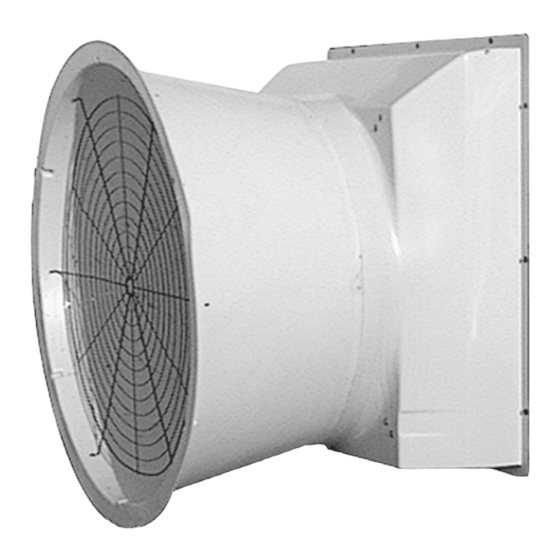
TURBO
Fiberglass Cone and Grill Fans
®
36" Belt Drive
Installation & Operator's Instruction Manual
Mv1680-001 02/01
Mv1680-002 02/01
Operating static pressure should be less than 0.15 inches water column [37 Pa].
The Fan Inlet and exhaust must be kept clear of obstructions. Failure to keep the Fan airflow path clear of
obstructions could cause loss of Fan performance and Fan damage.
November 2021
MV1680K
Advertisement
Table of Contents

Related Manuals for Chore-Time Mv1680-001


Summary of Contents for Chore-Time Mv1680-001
- Page 1 ® 36" Belt Drive Installation & Operator’s Instruction Manual Mv1680-001 02/01 Mv1680-002 02/01 Operating static pressure should be less than 0.15 inches water column [37 Pa]. The Fan Inlet and exhaust must be kept clear of obstructions. Failure to keep the Fan airflow path clear of obstructions could cause loss of Fan performance and Fan damage.
-
Page 2: Table Of Contents
Chore-Time Extended Warranty ........ -
Page 3: Chore-Time Extended Warranty
Warranty period (“Extended Warranty Period”) with respect to certain Product parts (“Component Part”) as set forth in the table below. If such a defect is determined by Chore-Time to exist within the applicable period, Chore-Time will, at its option, (a) repair the Product or Component Part free of charge, F.O.B. the factory of manufacture or (b) replace the Product or Component Part free of charge, F.O.B. -
Page 4: General
Contents also specifies which pages contain information for the sales personnel, installer, and consumer (end user). Important! Chore-Time Equipment strongly recommends that a good alarm system should be installed in confinement buildings to warn of power failure and high temperature. Chore-time Equipment also recommends that an alternate power source be available for confinement buildings in case of power failure. -
Page 5: About This Manual
36" Belt DriveAbout This Manual About This Manual The intent of this manual is to help you in two ways. One is to follow step-by-step in the order of assembly of your product. The other way is for easy reference if you have questions in a particular area. -
Page 6: Follow Safety Instructions
Safety Information36" Belt Drive Follow Safety Instructions Carefully read all safety messages in this manual and on your equipment safety signs. Follow recommended precautions and safe operating practices. Keep safety signs in good condition. Replace missing or damaged safety signs. Decal Descriptions DANGER: Electrical Hazard Disconnect electrical power before inspecting or servicing equipment unless... -
Page 7: Decal Location
36" Belt DriveFan Installation Decal Location This diagram shows the proper location of the Safety Decal and a Identification Decal (the identification decal will be different depending on the type of fan purchased) as shipped from the factory. Replace damaged or missing decals. Make sure the decals can be easily seen at all times. -
Page 8: Planning The Installation Continued
Fan Installation36" Belt Drive Planning the Installation Continued..Mv1680-009 02/01 Rough Frame Opening Minimum 45.38" 43.00" 0" 27" (115.27 cm) (109.22 cm) (0.00 cm) (68.58 cm) Figure 2.Planning and Layout Diagram for Grill Fans Installing the Fan to the Framed Opening 1.Cut an opening in the wall to house the fan—the required wall opening is provided in the chart below (See Figure 3.). -
Page 9: Installing The Cone Or Grill To The Fiberglass Fan
36" Belt DriveFan Installation 3.Insert the Fan Assembly in the wall opening and secure using the (12) 1/4 x 1-3/4 Lag Screws, Shutter Clips, and Nylon Washers provided. The Shroud is pre-drilled (3 holes per side).The hardware must be installed as shown in Figure 4 below. This allows for rotation of the Shutter Clips when installing the Shutter. - Page 10 Fan Installation36" Belt Drive Fiberglass Grill Fan: 1.Align the holes in the Grill with the slots in the Shroud. 2.Insert the (6) Wafer Head Bolts from inside the Shroud through the Grill and thread the Flange Nuts onto the ends of the Wafer Head Bolts. Description Part No.
-
Page 11: Remove Nylon Ties
36" Belt DriveFan Installation Remove Nylon Ties 1.Cut and Remove Nylon Ties from the Driven Sheave and the Motor (See Figure 7.) Nylon Tie Figure 7.Removing Nylon Tie’s Installing the Belt and Tension Spring 1.Install the Belt as shown. 2. Install the Tension Spring in the 5th notch from the top (See Figure 8.) Belt Nylon Tie 5th notch from the Top... -
Page 12: Shutter Installation/Cord Routing And Wiring
Fan Installation36" Belt Drive Shutter Installation/Cord Routing and Wiring 1.See Wiring diagram on Motor for Motor electrical connections. Follow local, state, and national electrical codes for wiring. 2.Install an electrical disconnect within reach of each Fan. 3.Route the motor cord (not supplied) toward the upper left corner of the Fan and attach the cord to the Motor Mount using the three Cable Ties—included in the hardware package. -
Page 13: Maintenance
36" Belt DriveMaintenance Maintenance Service and maintenance of fans should be done only by a qualified technician. Disconnect Power prior to maintaining or cleaning the fan! The fan may start automatically causing injury or death. 1.Keep the fan clean for maximum life and performance. 2.Clean Shutter, Cone and Shroud for maximum life and performance. -
Page 14: Fan Assembly Part Numbers
Fan Assembly Part Numbers Fan Assembly Fan Sub- Fan Interior Motor Outlet Voltage PH HP Motor P/N Assembly P/N Color Sheave P/N 46777-3604 46974-024 black Grill 1381 46777-3624 46974-224 black Grill 208-230 40158 1381 46777-3644 46974-424 black Grill 208-230/460 4714 1381 46777-3654 46974-524... - Page 15 36" Belt DriveFan Assembly Part Numbers This page left blank intentionally..MV1680K...
-
Page 16: Part Numbers
Part Numbers Belt Drive TURBO® Fan Parts... -
Page 17: Plastic Shutter Part Numbers
1" Cast Pillow Block Bearing 50553 5/16-18x.75 SS Carr. Bolt 27868-1 1/4 x 1-1/8 Sq. Key 2419-2 Upper Motor Mount Support 37735 Chore-Time Decal 2525-4 36" Fiber Glass Fan Shroud 37913 Self Tension Motor Mount 39677 36" Fiber Glass Fan Shroud (Black) 46970... - Page 18 Description of Change 35516 Removed Balloons 31,32,33 Added obstruction and static pressure warning statements For additional parts and information, contact your nearest Chore-Time distributor or representative. Find your nearest distributor at: www.choretime.com/contacts CTB, Inc. PO Box 2000 Milford, Indiana 46542-2000 USA Phone (574) 658-4101 Fax (877) 730-8825 Email: choretime@choretime.com...
Need help?
Do you have a question about the Mv1680-001 and is the answer not in the manual?
Questions and answers