Table of Contents
Advertisement
Quick Links
SuperServer
®
6029TP-HTR
6029TP-HC0R
6029TP-HC1R
USER'S MANUAL
Revision 1.0
The information in this User's Manual has been carefully reviewed and is believed to be accurate. The vendor assumes
no responsibility for any inaccuracies that may be contained in this document, and makes no commitment to update
or to keep current the information in this manual, or to notify any person or organization of the updates. Please Note:
For the most up-to-date version of this manual, please see our website at www.supermicro.com.
Super Micro Computer, Inc. ("Supermicro") reserves the right to make changes to the product described in this manual
at any time and without notice. This product, including software and documentation, is the property of Supermicro and/
or its licensors, and is supplied only under a license. Any use or reproduction of this product is not allowed, except
as expressly permitted by the terms of said license.
IN NO EVENT WILL Super Micro Computer, Inc. BE LIABLE FOR DIRECT, INDIRECT, SPECIAL, INCIDENTAL,
SPECULATIVE OR CONSEQUENTIAL DAMAGES ARISING FROM THE USE OR INABILITY TO USE THIS PRODUCT
OR DOCUMENTATION, EVEN IF ADVISED OF THE POSSIBILITY OF SUCH DAMAGES. IN PARTICULAR, SUPER
MICRO COMPUTER, INC. SHALL NOT HAVE LIABILITY FOR ANY HARDWARE, SOFTWARE, OR DATA STORED
OR USED WITH THE PRODUCT, INCLUDING THE COSTS OF REPAIRING, REPLACING, INTEGRATING,
INSTALLING OR RECOVERING SUCH HARDWARE, SOFTWARE, OR DATA.
Any disputes arising between manufacturer and customer shall be governed by the laws of Santa Clara County in the
State of California, USA. The State of California, County of Santa Clara shall be the exclusive venue for the resolution
of any such disputes. Supermicro's total liability for all claims will not exceed the price paid for the hardware product.
FCC Statement: This equipment has been tested and found to comply with the limits for a Class A digital device
pursuant to Part 15 of the FCC Rules. These limits are designed to provide reasonable protection against harmful
interference when the equipment is operated in a commercial environment. This equipment generates, uses, and can
radiate radio frequency energy and, if not installed and used in accordance with the manufacturer's instruction manual,
may cause harmful interference with radio communications. Operation of this equipment in a residential area is likely
to cause harmful interference, in which case you will be required to correct the interference at your own expense.
California Best Management Practices Regulations for Perchlorate Materials: This Perchlorate warning applies only
to products containing CR (Manganese Dioxide) Lithium coin cells. "Perchlorate Material-special handling may apply.
See www.dtsc.ca.gov/hazardouswaste/perchlorate".
WARNING: Handling of lead solder materials used in this product may expose you to lead, a
chemical known to the State of California to cause birth defects and other reproductive harm.
The products sold by Supermicro are not intended for and will not be used in life support systems, medical equipment,
nuclear facilities or systems, aircraft, aircraft devices, aircraft/emergency communication devices or other critical
systems whose failure to perform be reasonably expected to result in significant injury or loss of life or catastrophic
property damage. Accordingly, Supermicro disclaims any and all liability, and should buyer use or sell such products
for use in such ultra-hazardous applications, it does so entirely at its own risk. Furthermore, buyer agrees to fully
indemnify, defend and hold Supermicro harmless for and against any and all claims, demands, actions, litigation, and
proceedings of any kind arising out of or related to such ultra-hazardous use or sale.
Manual Revision 1.0
Release Date: August 29, 2017
Unless you request and receive written permission from Super Micro Computer, Inc., you may not copy any part of this
document. Information in this document is subject to change without notice. Other products and companies referred
to herein are trademarks or registered trademarks of their respective companies or mark holders.
Copyright © 2017 by Super Micro Computer, Inc.
All rights reserved.
Printed in the United States of America
Advertisement
Table of Contents

Subscribe to Our Youtube Channel
Related Manuals for Supermicro SuperServer 6029TP-HTR


Summary of Contents for Supermicro SuperServer 6029TP-HTR
- Page 1 State of California, USA. The State of California, County of Santa Clara shall be the exclusive venue for the resolution of any such disputes. Supermicro's total liability for all claims will not exceed the price paid for the hardware product.
-
Page 2: Table Of Contents
If you have any questions, please contact our support team at: Choosing a Setup Location ....................18 support@supermicro.com Rack Precautions ......................18 This manual may be periodically updated without notice. Please check the Supermicro website for possible updates to the manual revision level. Server Precautions ......................19 Rack Mounting Considerations ..................19 Warnings Ambient Operating Temperature ..................19... - Page 3 SuperServer 6029TP-HTR/HC0R/HC1R User's Manual Preface Chapter 3 Maintenance and Component Installation Adapter Card Replacement ....................54 Installing an Add-on Card....................55 3.1 Removing Power ........................26 3.2 Accessing the System ......................26 Power Supply ........................57 3.3 Motherboard Components ....................27 Power Supply Replacement ..................57 Chapter 4 Motherboard Connections Processor and Heatsink Installation ..................27...
- Page 4 SuperServer 6029TP-HTR/HC0R/HC1R User's Manual Contacting Supermicro Headquarters Address: Super Micro Computer, Inc. 980 Rock Ave. San Jose, CA 95131 U.S.A. Tel: +1 (408) 503-8000 Fax: +1 (408) 503-8008 Email: marketing@supermicro.com (General Information) support@supermicro.com (Technical Support) Website: www.supermicro.com Europe Address: Super Micro Computer B.V.
-
Page 5: Chapter 1 Introduction
One (1) PCI-Express 3.0 x16 slot supported by CPU1 (SXB3_1) One (1) PCI-Express 3.0 x8 slot supported by CPU2 (SXB3_2) Inspect the box the SuperServer 6029TP-HTR/HC0R/HC1R was shipped in and note if it was One (1) PCI-E 3.0 x16 slot supported by CPU2 (SXB4) damaged in any way. -
Page 6: Twin2: System Notes
Hard Drive Backplane/Drives As a system, the SuperServer 6029TP-HTR/HC0R/HC1R supports the use of 12 hard drives (SAS or SATA). A single backplane works to apply system-based control for power and fan speed functions, yet at the same time logically connects a set of three hard drives to each of the four nodes. -
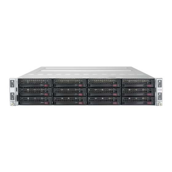
Page 7: Front Features
SuperServer 6029TP-HTR/HC0R/HC1R User's Manual Chapter 1: Introduction Front Features Control Panel Features The SC827HQ+-R2K04BP3 is a mini 2U chassis See the illustration below for the features Item Feature Description included on the front of the chassis. The main power button on each of the control panels is used to apply or... -
Page 8: Rear Features
SuperServer 6029TP-HTR/HC0R/HC1R User's Manual Chapter 1: Introduction Rear Features 1.5 Motherboard Layout The illustration below shows the features included on the rear of the chassis. Below is a layout of the X11DPT-PS with jumper, connector and LED locations shown. See the table on the following page for descriptions. -
Page 9: Quick Reference Table
SuperServer 6029TP-HTR/HC0R/HC1R User's Manual Chapter 1: Introduction DIMMA2 Quick Reference Table DIMMJ1 DIMMA1 DIMMH1 DIMMB1 DIMMG1 Jumper Description Default Setting DIMMC1 VCCP0 VCCP1 DIMMG2 VR13 VR13 DIMMD2 5+1 PHASE 5+1 PHASE DIMMM1 JBT1 CMOS Clear Open (Normal) 165W UPI 10.4/1.2G... -
Page 10: Chapter 2 Server Installation
SuperServer 6029TP-HTR/HC0R/HC1R User's Manual Chapter 2: Server Installation Chapter 2 • Always make sure the rack is stable before extending a server or other component from the rack. • You should extend only one server or component at a time - extending two or more simul- Server Installation taneously may cause the rack to become unstable. -
Page 11: Circuit Overloading
SuperServer 6029TP-HTR/HC0R/HC1R User's Manual Chapter 2: Server Installation Identifying the Rails Circuit Overloading Consideration should be given to the connection of the equipment to the power supply circuitry The rack rails and the related hardware should have been included with the system. Refer and the effect that any possible overloading of circuits might have on overcurrent protection to Figure 2-1 to identify the rail sections. -
Page 12: Locking Tabs
SuperServer 6029TP-HTR/HC0R/HC1R User's Manual Chapter 2: Server Installation Locking Tabs Installing the Chassis Rails Each inner rail has a locking tab. This tab locks the chassis into place when installed and Begin the rack mounting procedure by installing the inner rails to the server chassis. -
Page 13: Installing The Outer Rails On The Rack
SuperServer 6029TP-HTR/HC0R/HC1R User's Manual Chapter 2: Server Installation Installing the Outer Rails on the Rack Standard Chassis Installation Determine where you want to place the server in the rack (see the Rack and Server Installing the Chassis into a Rack Precautions in Section 2.2). -
Page 14: Chapter 3 Maintenance And Component Installation
CPU socket cap is in place and that none of the socket pins are bent; otherwise, contact your retailer immediately. • Refer to the Supermicro website for updates on CPU support. • Please follow the instructions given in the ESD Warning section on the first page of this chapter before handling, installing, or removing system components. - Page 15 SuperServer 6029TP-HTR/HC0R/HC1R User's Manual Chapter 3: Maintenance and Component Installation The Skylake Series Processor Overview of the Processor Socket Assembly The processor socket assembly contains 1) the Intel SKX(-F) processor, 2) the narrow processor clip, 3) the dust cover, and 4) the CPU socket.
- Page 16 SuperServer 6029TP-HTR/HC0R/HC1R User's Manual Chapter 3: Maintenance and Component Installation Overview of the Processor Heatsink Module (PHM) Attaching the Non-F Model Processor to the Narrow Processor Clip to Create the Processor Package Assembly The Processor Heatsink Module (PHM) contains 1) a heatsink, 2) a narrow processor clip, and 3) the SKX(-F) processor.
- Page 17 SuperServer 6029TP-HTR/HC0R/HC1R User's Manual Chapter 3: Maintenance and Component Installation Attaching the F-Model Processor to the Narrow Processor Clip to Create Attaching the Non-F Model Processor Package Assembly to the Heatsink to the Processor Package Assembly Form the Processor Heatsink Module (PHM) To properly install the CPU into the narrow processor clip, please follow the steps below.
- Page 18 SuperServer 6029TP-HTR/HC0R/HC1R User's Manual Chapter 3: Maintenance and Component Installation Attaching the F Model Processor Package Assembly to the Heatsink to Preparing the CPU Socket for Installation Form the Processor Heatsink Module (PHM) This motherboard comes with the CPU socket pre-assembled in the factory. The CPU socket After you have made a processor package assembly by following the instructions on the contains 1) a dust cover, 2) a socket bracket, 3) the CPU (P0) socket, and 4) a back plate.
- Page 19 SuperServer 6029TP-HTR/HC0R/HC1R User's Manual Chapter 3: Maintenance and Component Installation Installing the Processor Heatsink Module (PHM) Removing the Processor Heatsink Module (PHM) from the Motherboard 1. Once you have assembled the processor heatsink module (PHM) by following the Before removing the processor heatsink module (PHM), unplug power cord from the power instructions listed on page 29 or page 30, you are ready to install the processor heatsink outlet.
- Page 20 Warning! Exercise extreme care when installing or removing DIMM modules to prevent any (SPC) and DIMMs per Channel (DPC) Ranks Per DIMM Capacity (GB) possible damage. Check the Supermicro website for recommended memory modules. 1 Slot per Channel Type DIMM and...
- Page 21 SuperServer 6029TP-HTR/HC0R/HC1R User's Manual Chapter 3: Maintenance and Component Installation • (DDR4 Only) 2SPC Memory Configuration with x8 DIMMs There should be at least one DDR4 DIMM per socket. • If only one DIMM is populated in a channel, then populate it in the slot furthest away...
- Page 22 (128-bit) memory, which is faster than non-interleaved DDR1: Populate identically as DDR0 (64-bit) memory. DDR2: Populate identically as DDR1 >1 Check the Supermicro website for possible updates to memory support. 4 x4 DIMMs DDR0: Populate with 2 DIMMs DDR1: Populate identically as DDR0 Installing Memory...
- Page 23 SuperServer 6029TP-HTR/HC0R/HC1R User's Manual Chapter 3: Maintenance and Component Installation Note: Visit the product page on the Supermicro website for possible updates to memory support (www.supermicro.com). DIMM Removal Reverse the steps above to remove the DIMM modules from the motherboard.
- Page 24 You do not need to access the inside of the chassis or remove power to replace or swap drives. Proceed to the next step for instructions. You must use standard 1" high, drives in the system. Note: Refer to Supermicro's web site for setup guidelines: <http://www.supermicro.com/ support/manuals/>.
- Page 25 Figure 3-11. Chassis Drive Tray Drive Tray Figure 3-13. Installing the Hard Drive Note: Enterprise level hard disk drives are recommended for use in Supermicro chassis and servers. For information on recommended HDDs, visit the Supermicro website at http://www. supermicro.com/products/nfo/files/storage/SBB-HDDCompList.pdf Figure 3-12.
- Page 26 SuperServer 6029TP-HTR/HC0R/HC1R User's Manual Chapter 3: Maintenance and Component Installation Hard Drive Carrier Indicators Each hard drive carrier has two LED indicators: an activity indicator and a status indicator. In RAID configurations, the status indicator lights to indicate the status of the drive. In non-RAID configurations, the status indicator remains off.
- Page 27 SuperServer 6029TP-HTR/HC0R/HC1R User's Manual Chapter 3: Maintenance and Component Installation 7. Confirm that the fan is working properly before replacing the chassis cover. Air Shroud Air shrouds concentrate airflow to maximize fan efficiency. The SC827HQ+ chassis air shroud does not require screws to set up. The 6029TP-HTR/HC0R/HC1R requires four identical air shrouds, one in each serverboard drawer (p/n MCP-310-21703-0B).
- Page 28 SuperServer 6029TP-HTR/HC0R/HC1R User's Manual Chapter 3: Maintenance and Component Installation Adapter Card Replacement Installing the Adapter Card (Figure 6-11) 1. Place the adapter card in the serverboard drawer, aligning the holes in the adapter card Each serverboard drawer comes equipped with an adapter card which plugs into the with the holes in the serverboard drawer.
- Page 29 The SC827HQ+ chassis utilizes two redundant power supplies. In the unlikely event that the power supply unit needs to be replaced, one power supply can be removed, without powering down the system. Replacement units can be ordered directly from Supermicro (See the contact information in the Preface of this manual).
-
Page 30: Chapter 4 Motherboard Connections
I-SATA0-3 are supported by CPU2 PCI-E 3.0 x16 slot on SXB2, and S-SATA0-5 are supported 4.2 Headers and Connectors by the CPU1 PCI-E 3.0 x8 slot on SXB1. I-SATA4/ I-SATA5 can be used with Supermicro Onboard Fan Header SuperDOMs, which are yellow SATA DOM connectors with power pins built in, and do not An onboard fan header (FAN3) is located next to COM port (COM1) on the motherboard. -
Page 31: Ports
SuperServer 6029TP-HTR/HC0R/HC1R User's Manual Chapter 4: Motherboard Connections 4.3 Ports VGA Port The onboard VGA port is located next to IPMI_LAN on the I/O back panel. Use this connection See Figure 4-1 below for the locations and descriptions of the various I/O ports on the rear for VGA display. -
Page 32: Jumpers
Note: UID can also be triggered via IPMI on the motherboard. For more information on IPMI, Pin 1 is identified with a square solder pad on the printed circuit board. See the motherboard please refer to the IPMI User's Guide posted on our website at http://www.supermicro.com. layout page for jumper locations. -
Page 33: Led Indicators
SuperServer 6029TP-HTR/HC0R/HC1R User's Manual Manufacturing Mode Select Close JPME1 to bypass SPI flash security and force the system to use the Manufacturing Mode, which will allow you to flash the system firmware from a host server to modify system settings. See the table below for jumper settings. -
Page 34: Chapter 5 Software
You must first configure RAID settings (if using RAID) before you install the Windows OS and the software drivers. To configure RAID settings, please refer to the RAID Configuration User Guides posted on our website at www.supermicro.com/support/manuals. Installing the Windows OS for a RAID System 1. -
Page 35: Driver Installation
The Supermicro FTP site contains drivers and utilities for your system at ftp://ftp.supermicro. The Supermicro SuperDoctor 5 is a program that functions in a command-line or web-based com. Some of these must be installed, such as the chipset driver. interface for Windows and Linux operating systems. The program monitors such system health... -
Page 36: Ipmi
SuperServer 6029TP-HTR/HC0R/HC1R User's Manual 5.4 IPMI The X11DPT-PS support the Inteliigent Platform Management Interface (IPMI). IPMI is used to provide remote access, monitoring and management. There are several BIOS settings that are related to IPMI. For general documentation and information on IPMI, please visit our website at:... -
Page 37: Chapter 6 Bios
Chapter 4: BIOS Chapter 6 BIOS 6.1 Introduction This chapter describes the AMIBIOS™ Setup utility for theX11DPT-PS X11DPT-PS motherboard. The BIOS is stored on a chip and can be easily upgraded using a flash program. Note: Due to periodic changes to the BIOS, some settings may have been added or deleted and might not yet be recorded in this manual. -
Page 38: Main Setup
SuperServer 6029TP-HTR/HC0R/HC1R User's Manual Chapter 4: BIOS 6.2 Main Setup Build Date This item displays the date when the version of the BIOS ROM used in the system was built. When you first enter the AMI BIOS setup utility, you will enter the Main setup screen. You can always return to the Main setup screen by selecting the Main tab on the top of the screen. - Page 39 SuperServer 6029TP-HTR/HC0R/HC1R User's Manual Chapter 4: BIOS Warning: Take Caution when changing the Advanced settings. An incorrect value, an incorrect Port 61h Bit-4 Emulation DRAM frequency, or an incorrect BIOS timing setting may cause the system to malfunction. Select Enabled for I/O Port 61h-Bit 4 emulation support to enhance system performance. The When this occurs, restore the setting to the manufacture default setting.
- Page 40 SuperServer 6029TP-HTR/HC0R/HC1R User's Manual Chapter 4: BIOS CPU Configuration PPIN Control Select Unlock/Enable to use the Protected-Processor Inventory Number (PPIN) in the system. Warning: Setting the wrong values in the following sections may cause the system to malfunc- The options are Unlock/Enable and Unlock/Disable.
- Page 41 SuperServer 6029TP-HTR/HC0R/HC1R User's Manual Chapter 4: BIOS Advanced Power Management Configuration Enhanced Halt State (C1E) Select Enable to enable "Enhanced Halt State" support, which will significantly reduce the CPU's power consumption by minimizing CPU's clock cycles and reduce voltage during a CPU P State Control ...
- Page 42 SuperServer 6029TP-HTR/HC0R/HC1R User's Manual Chapter 4: BIOS • UPI PCI-E Configuration Base/Size tCCD_L Relaxation If this feature is set to Enable, SPD (Serial Presence Detect) will override tCCD_L ("Column Degrade Precedence to Column Delay-Long", or “Command to Command Delay-Long” on the column side.) If Use this feature to select the degrading precedence option for Ultra Path Interconnect this feature is set to Disable, tCCD_L will be enforced based on the memory frequency.
- Page 43 SuperServer 6029TP-HTR/HC0R/HC1R User's Manual Chapter 4: BIOS Memory Rank Sparing IOU1 (IIO PCIe Br2) Select Enable to support memory-rank sparing to optimize memory performance. The This feature configures the PCI-E Bifuraction setting for a PCI-E port specified by the user.
- Page 44 SuperServer 6029TP-HTR/HC0R/HC1R User's Manual Chapter 4: BIOS Disable TPH (TLP Processing Hint) Select Enable to support VT_D Posted Interrupt which will allow external interrupts to be sent directly from a direct-assigned device to a client machine in non-root mode to improve TPH is used for data-tagging with a destination ID and a few important attributes.
- Page 45 SuperServer 6029TP-HTR/HC0R/HC1R User's Manual Chapter 4: BIOS Server ME (Management Engine) Configuration SATA RAID Option ROM/UEFI Driver (Available when the item "Configure SATA as" is set to "RAID") This feature displays the following system ME configuration settings. Select EFI to load the EFI driver for system boot. Select Legacy to load a legacy driver for General ME Configuration system boot.
- Page 46 SuperServer 6029TP-HTR/HC0R/HC1R User's Manual Chapter 4: BIOS Support Aggressive Link Power Management MMIO High Base When this item is set to Enable, the sSATA AHCI controller manages the power use of the Use this feature to select the base memory size according to memory-address mapping for SATA link.
- Page 47 SuperServer 6029TP-HTR/HC0R/HC1R User's Manual Chapter 4: BIOS Network Stack Configuration Device Settings This feature displays the base I/O port address and the Interrupt Request address of a Network Stack serial port specified by the user. Select Enabled to enable PXE (Preboot Execution Environment) or UEFI (Unified Extensible Note: This item is hidden when Serial Port 1 is set to Disabled.
- Page 48 SuperServer 6029TP-HTR/HC0R/HC1R User's Manual Chapter 4: BIOS *If the item above set to Enabled, the following items will become available for configuration: Recorder Mode Select Enabled to capture the data displayed on a terminal and send it as text messages Console Redirection Settings (for COM1)
- Page 49 SuperServer 6029TP-HTR/HC0R/HC1R User's Manual Chapter 4: BIOS Bits Per second Putty KeyPad Use this feature to set the transmission speed for a serial port used in Console Redirection. This feature selects Function Keys and KeyPad settings for Putty, which is a terminal Make sure that the same speed is used in the host computer and the client computer.
- Page 50 SuperServer 6029TP-HTR/HC0R/HC1R User's Manual Chapter 4: BIOS Bits Per Second Trusted Computing (Available when a TPM device is installed and detected by the BIOS) This feature sets the transmission speed for a serial port used in Console Redirection. Make sure that the same speed is used in both host computer and the client computer. A When a TPM (Trusted-Platform Module) device is detected in your machine, the following lower transmission speed may be required for long and busy lines.
- Page 51 SuperServer 6029TP-HTR/HC0R/HC1R User's Manual Chapter 4: BIOS Endorsement Hierarchy Intel® Virtual RAID on CPU Select Enabled for Endorsement Hierarchy support, which contains separate controls to When this submenu is selected and the RAID devices are detected, the BIOS screen displays...
-
Page 52: Event Logs
SuperServer 6029TP-HTR/HC0R/HC1R User's Manual Chapter 4: BIOS 4.4 Event Logs When Log is Full Select Erase Immediately to immediately erase all errors in the SMBIOS event log when the Use this feature to configure Event Log settings. event log is full. Select Do Nothing for the system to do nothing when the SMBIOS event log is full. - Page 53 SuperServer 6029TP-HTR/HC0R/HC1R User's Manual Chapter 4: BIOS 6.5 IPMI Erase SEL Select Yes, On next reset to erase all system event logs upon next system reboot. Select Use this feature to configure Intelligent Platform Management Interface (IPMI) settings. Yes, On every reset to erase all system event logs upon each system reboot. Select No to keep all system event logs after each system reboot.
- Page 54 SuperServer 6029TP-HTR/HC0R/HC1R User's Manual Chapter 4: BIOS • 6.6 Security Settings Gateway IP Address: This feature displays the Gateway IP address for this computer. This should be in decimal and in dotted quad form (i.e., 192.168.10.253). This menu allows the user to configure the following security settings for the system.
- Page 55 SuperServer 6029TP-HTR/HC0R/HC1R User's Manual Chapter 4: BIOS Secure Boot Platform Key (PK) When you select this submenu and press the <Enter> key, the following items will display: This feature allows the user to enter and configure a set of values to be used as a platform •...
- Page 56 SuperServer 6029TP-HTR/HC0R/HC1R User's Manual Chapter 4: BIOS 6.7 Boot Settings Fixed Boot Order Priorities This feature prioritizes the order of a bootable device from which the system will boot. Press Use this feature to configure Boot Settings: <Enter> on each entry from top to bottom to select devices.
- Page 57 SuperServer 6029TP-HTR/HC0R/HC1R User's Manual Chapter 4: BIOS 6.8 Save & Exit Use this feature to remove an EFI boot option from the boot priority list. Add New Driver Option Select the Save & Exit tab from the BIOS setup screen to configure the settings below.
- Page 58 SuperServer 6029TP-HTR/HC0R/HC1R User's Manual Discard Changes Select this option and press <Enter> to discard all the changes and return to the AMI BIOS setup utility. Default Options Restore Optimized Defaults To set this feature, select Restore Defaults from the Exit menu and press <Enter> to load manufacturer default settings which are intended for maximum system performance but not for maximum stability.
- Page 59 Appendix A: BIOS Codes Appendix A BIOS Codes A.1 BIOS Error POST (Beep) Codes During the POST (Power-On Self-Test) routines, which are performed each time the system is powered on, errors may occur. Non-fatal errors are those which, in most cases, allow the system to continue the boot-up process.
- Page 60 When BIOS performs the Power On Self Test, it writes checkpoint codes to I/O port 0080h. If the computer cannot complete the boot process, a diagnostic card can be attached to the computer to read I/O port 0080h (Supermicro p/n AOC-LPC80-20). For information on AMI updates, please refer to http://www.ami.com/products/.
- Page 61 Este símbolo de aviso indica peligro. Existe riesgo para su integridad física. Antes de Read this appendix in its entirety before installing or configuring components in the Supermicro manipular cualquier equipo, considere los riesgos de la corriente eléctrica y familiarícese chassis.
- Page 62 SuperServer 6029TP-HTR/HC0R/HC1R User's Manual Appendix B: Standardized Warning Statements . ٌ ا ك ً ف حالة و ٌ يك أى تتسبب ف اصابة جسذ ة ٌ هذا الزهز ع ٌ خطز !تحذ ز Warnung قبل أى تعول عىل أي هعذات،يك عىل علن بالوخاطز ال ا ٌجوة عي الذوائز...
- Page 63 SuperServer 6029TP-HTR/HC0R/HC1R User's Manual Appendix B: Standardized Warning Statements Power Disconnection Warning Warnung Dieses Produkt ist darauf angewiesen, dass im Gebäude ein Kurzschluss- bzw. Warning! The system must be disconnected from all sources of power and the power Überstromschutz installiert ist. Stellen Sie sicher, dass der Nennwert der Schutzvorrichtung cord removed from the power supply module(s) before accessing the chassis interior nicht mehr als: 250 V, 20 A beträgt.
- Page 64 SuperServer 6029TP-HTR/HC0R/HC1R User's Manual Appendix B: Standardized Warning Statements يجب فصم اننظاو من جميع مصادر انطاقت وإ ز انت سهك انكهرباء من وحدة امداد Attention انطاقت قبم Il est vivement recommandé de confier l'installation, le remplacement et la maintenance de ces équipements à...
- Page 65 SuperServer 6029TP-HTR/HC0R/HC1R User's Manual Appendix B: Standardized Warning Statements Battery Handling Warnung Diese Einheit ist zur Installation in Bereichen mit beschränktem Zutritt vorgesehen. Der Zutritt zu derartigen Bereichen ist nur mit einem Spezialwerkzeug, Schloss und Schlüssel oder einer Warning! There is the danger of explosion if the battery is replaced incorrectly. Replace sonstigen Sicherheitsvorkehrung möglich.
- Page 66 SuperServer 6029TP-HTR/HC0R/HC1R User's Manual Appendix B: Standardized Warning Statements هناك خطر من انفجار يف حالة اسحبذال البطارية بطريقة غري صحيحة فعليل ¡Advertencia! اسحبذال البطارية Puede que esta unidad tenga más de una conexión para fuentes de alimentación. Para cortar por completo el suministro de energía, deben desconectarse todas las conexiones.
- Page 67 SuperServer 6029TP-HTR/HC0R/HC1R User's Manual Appendix B: Standardized Warning Statements Backplane Voltage هناك خطز مه التيار الكهزبايئ أوالطاقة املىجىدة عىل اللىحة عندما يكىن النظام يعمل كه حذ ر ا عند خدمة هذا الجهاس Warning! Hazardous voltage or energy is present on the backplane when the system is operating.
- Page 68 SuperServer 6029TP-HTR/HC0R/HC1R User's Manual Appendix B: Standardized Warning Statements תיאום חוקי החשמל הארצי Attention !אזהרה La mise au rebut ou le recyclage de ce produit sont généralement soumis à des lois et/ou .התקנת הציוד חייבת להיות תואמת לחוקי החשמל המקומיים והארציים...
- Page 69 제거할 때 팬은 여전히 회전하고 있을 수 있습니다. 팬 조림품 외관의 열려있는 부분들로부터 Feuer verursachen. Die Richtlinien untersagen das Nutzen von UL oder CAS zertifizierten 손가락 및 스크류드라이버, 다른 물체들이 가까이 하지 않도록 배치해 주십시오. Kabeln (mit UL/CSA gekennzeichnet), an Geräten oder Produkten die nicht mit Supermicro Waarschuwing gekennzeichnet sind.
- Page 70 حجم املوصل والقابس السليم. استخدام أي كابالت ومحوالت أخرى قد يتسبب يف عطل أو حريق. يحظر قانون السالمة لألجهزة الكهربائية واملعدات استخدام الكابالت املعتمدة من قبلUL أوCSA ( والتي تحمل عالمةUL/CSA) مع أي معدات أخرى غري املنتجات املعنية واملحددة من قبلSupermicro.
- Page 71 Integrated memory controller supports up to 2 TB of 3DS LRDIMM/RDIMM/NVDIMM DDR4 (288-pin) ECC 2666/2400/2133 MHz modules in sixteen (16) slots at up to 128GB at 1.2V. Note: For the latest CPU/memory updates, please refer to our website at http://www.supermicro.com/products/motherboard. SATA Controller...
- Page 72 SuperServer 6029TP-HTR/HC0R/HC1R User's Manual Regulatory Compliance Electromagnetic Emissions: FCC Class A, EN 55022 Class A, EN 61000-3-2/3-3, CISPR 22 Class A Electromagnetic Immunity: EN 55024/CISPR 24, (EN 61000-4-2, EN 61000-4-3, EN 61000-4-4, EN 61000-4-5, EN 61000-4-6, EN 61000-4-8, EN 61000-4-11)
- Page 73 Warning: Do not upgrade the BIOS unless your system has a BIOS-related issue. Flashing the wrong BIOS can cause irreparable damage to the system. In no event shall Supermicro be liable for direct, indirect, special, incidental, or consequential damages arising from a BIOS update.
- Page 74 SuperServer 6029TP-HTR/HC0R/HC1R User's Manual Appendix D: UEFI BIOS Recovery The file system supported by UEFI is FAT (including FAT12, FAT16, and FAT32) which is Warning: Please stop pressing the <Ctrl> and <Home> keys immediately when you see the installed on a bootable or non-bootable USB-attached device. However, the BIOS might need several minutes to locate the SUPER.ROM file if the media size becomes too large due to...
- Page 75 SuperServer 6029TP-HTR/HC0R/HC1R User's Manual Appendix D: UEFI BIOS Recovery 5. When the screen as shown above displays, use the arrow keys to select the item 8. Press <Del> continuously during system boot to enter the BIOS setup utility. From the top of the tool bar, click on Boot and press <Enter>...
Need help?
Do you have a question about the SuperServer 6029TP-HTR and is the answer not in the manual?
Questions and answers