Table of Contents

Related Manuals for StarTech.com ARMDUAL2


Summary of Contents for StarTech.com ARMDUAL2
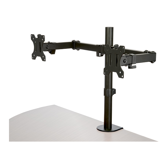
- Page 1 Desk Mount Dual Monitor Arm | Crossbar Design | Articulating Actual product may vary from photos User Manual SKU#: ARMDUAL2 For the latest information and specifications visit www.startech.com/AMRDUAL2 Manual Revision: 09/23/2019...
- Page 2 This manual may make reference to trademarks, registered trademarks, and other protected names and/or symbols of third-party companies not related in any way to StarTech.com. Where they occur these references are for illustrative purposes only and do not represent an endorsement of a product or service by StarTech.com, or an endorsement of the product(s) to which this manual...
-
Page 3: Warning Statements
Il prodotto è in grado di supportare i seguenti pesi: 2 x 8 kg. • Il prodotto è destinato all’uso in ambienti interni. Se ne sconsiglia l’impiego in ambienti esterni. To view manuals, videos, drivers, downloads, technical drawings, and more visit www.startech.com/support... - Page 4 • Dit product is alleen bedoeld voor binnengebruik en mag niet buiten worden gebruikt. 注意 • 必ず取扱説明書に従って本製品の組み立てを行って下さい。 • 本製品で定められた最大積載重量を超えないようにして下さい。 最大積載重量をオーバーした 場合、 怪我をする恐れや器物破損の恐れがあります。 本製品は、 モニター1台あたり2 x 8kgまで 支持できます。 • 本製品は、 室内での使用を想定しています。 戸外では使用しないで下さい。 To view manuals, videos, drivers, downloads, technical drawings, and more visit www.startech.com/support...
-
Page 5: Table Of Contents
Attaching the Monitors (Flush) ............24 Attaching the Monitors (Recessed) .............26 Mounting the Monitors .................28 Adjusting the Monitors .................30 Tilt Adjustment ............................30 Micro Adjustments ........................... 31 Routing the Cables .................33 To view manuals, videos, drivers, downloads, technical drawings, and more visit www.startech.com/support... -
Page 6: Product Diagram
Product Diagram Swivel Arm Assembly C- Clamp VESA Mount x 2 Grommet Pole Cable Management Clips To view manuals, videos, drivers, downloads, technical drawings, and more visit www.startech.com/support... -
Page 7: Product Dimensions
Product Dimensions To view manuals, videos, drivers, downloads, technical drawings, and more visit www.startech.com/support... -
Page 8: Product Information
Product Information Package Contents VESA Mounts Swivel Arm Assembly Qty: Two Qty: One C-Clamp Assembly Pole Qty: One Qty: One To view manuals, videos, drivers, downloads, technical drawings, and more visit www.startech.com/support... - Page 9 Pole Cap Cable Management Clip Qty: One Qty: Two Grommet Base Plate Micro-Adjustment Knobs Qty: One Qty: Two Micro-Adjustment Knob Screws Rubber Pads Qty: Two Qty: Five To view manuals, videos, drivers, downloads, technical drawings, and more visit www.startech.com/support...
- Page 10 Qty: One 4 mm Hex Key 6 mm Hex Key Qty: One Qty: One M4 x 12 mm Screws M4 x 16 mm Screws Qty: Eight Qty: Eight To view manuals, videos, drivers, downloads, technical drawings, and more visit www.startech.com/support...
- Page 11 M5 x 12 mm Screws M5 x 16 mm Screws Qty: Eight Qty: Eight Washers Spacers Qty: Eight Qty: Sixteen Swivel Arm Cable Clip 3 mm Hex Key Qty: Four Qty: One To view manuals, videos, drivers, downloads, technical drawings, and more visit www.startech.com/support...
-
Page 12: Product Specifications
Product Specifications 75 x 75 100 x 100 VESA 35.2 lb. (2 x 8 kg) Total Weight (two monitors) Max. 32 “ Screen Size Rotation To view manuals, videos, drivers, downloads, technical drawings, and more visit www.startech.com/support... -
Page 13: Requirements
- 45 to +45 Tilt - 90 to +90 Swivel Requirements Phillips Head Screwdriver x 1 • Monitors x 2 • Mounting Surface x 1 • To view manuals, videos, drivers, downloads, technical drawings, and more visit www.startech.com/support... -
Page 14: Mounting The Monitor Arm Using The C-Clamp
Screw Holes on the bottom of the Pole. Insert the three Pole Assembly Screws through the Screw Holes on the top of the C-Clamp and into the Screw Holes on the bottom of the Pole. To view manuals, videos, drivers, downloads, technical drawings, and more visit www.startech.com/support... - Page 15 While supporting the weight of the Monitor Arm, slide the C-Clamp over the edge of the Mounting Surface. Using your hand, tighten the Knob until the C-Clamp is pressed tightly against the Mounting Surface. To view manuals, videos, drivers, downloads, technical drawings, and more visit www.startech.com/support...
- Page 16 Swivel Arm Assembly. Installing the Arm Assembly Clips Slide the Swivel Arm Assembly over-top of the Pole, until the Swivel Arm Assembly comes in contact with the Collar. To view manuals, videos, drivers, downloads, technical drawings, and more visit www.startech.com/support...
- Page 17 While holding the weight of the Swivel Arm Assembly, use the 6 mm Hex Key to tighten the Adjustment Screw on the Swivel Arm Assembly to secure the Swivel Arm Assembly in place. To view manuals, videos, drivers, downloads, technical drawings, and more visit www.startech.com/support...
-
Page 18: Using The Grommet Mount
Tightening the Swivel Arm Using the Grommet Mount Insert the Pole Cap into the top of the Pole. Installing the Pole Cap To view manuals, videos, drivers, downloads, technical drawings, and more visit www.startech.com/support... - Page 19 Using a Phillips Head Screw Driver, remove the small screw attached to the Knob onto the C-Clamp. Removing the Knob Remove the backing from the Rubber Pads (x 5). To view manuals, videos, drivers, downloads, technical drawings, and more visit www.startech.com/support...
- Page 20 On the under side of the Mounting Surface, align the Grommet Plate with the Grommet Hole. Insert the Knob through the Grommet Plate and Grommet Hole and into the Grommet Base Plate and Pole. To view manuals, videos, drivers, downloads, technical drawings, and more visit www.startech.com/support...
- Page 21 Installing the Grommet Tighten the Knob, until the Grommet Plate and Knob are pushing tightly against the bottom of the Mounting Surface. To view manuals, videos, drivers, downloads, technical drawings, and more visit www.startech.com/support...
- Page 22 Using the 3 mm Hex Key, tighten the Adjustment Screw on the side of the Collar, securing the Collar to the Pole. Clip the Arm Assembly Clips (x 4) into place along the Swivel Arm Assembly. To view manuals, videos, drivers, downloads, technical drawings, and more visit www.startech.com/support...
- Page 23 Installing the Arm Assembly Clips Slide the Swivel Arm Assembly over-top of the Pole, until the Swivel Arm Assembly comes in contact with the Collar. To view manuals, videos, drivers, downloads, technical drawings, and more visit www.startech.com/support...
- Page 24 While holding the weight of the Swivel Arm Assembly, use the 6 mm Hex Key to tighten the Adjustment Screw on the Swivel Arm Assembly to secure the Swivel Arm Assembly in place. To view manuals, videos, drivers, downloads, technical drawings, and more visit www.startech.com/support...
-
Page 25: Attaching The Monitors (Flush)
Determine the size and length of screw to use to mount the Monitors to the Monitor Mounts (M4 x 12 mm or M5 x 12 mm, if appropriate). To view manuals, videos, drivers, downloads, technical drawings, and more visit www.startech.com/support... - Page 26 Holes and into the Screw Holes in the back of the Monitor. Installing the VESA Mount Using a Phillips Head Screwdriver (sold separately) tighten the Screws, being careful not to over-tighten. To view manuals, videos, drivers, downloads, technical drawings, and more visit www.startech.com/support...
-
Page 27: Attaching The Monitors (Recessed)
Align the Washers (x 4) with the Mounting Holes on the VESA Mount. Insert the Screws (x 4) through the Washers and Mounting Holes and into the Screw Holes in the back of the Monitor. To view manuals, videos, drivers, downloads, technical drawings, and more visit www.startech.com/support... - Page 28 Screws, stop tightening. Failure to do so could result in damage to the monitor. Repeat steps 1 - 6 to mount the second Monitor. To view manuals, videos, drivers, downloads, technical drawings, and more visit www.startech.com/support...
-
Page 29: Mounting The Monitors
Micro-Adjustment Knob on the top of the Micro- Adjustment Screw Protrusion. Insert the Micro-Adjustment Screw through the center of the Micro-Adjustment Knob and into the Micro- Adjustment Screw Protrusion. To view manuals, videos, drivers, downloads, technical drawings, and more visit www.startech.com/support... - Page 30 Adjust the Monitor tilt until it is in the desired position. Using the 6 mm Hex Key, tighten the Adjustment Screw on the side of the Monitor Holder, securing the Monitor in place. To view manuals, videos, drivers, downloads, technical drawings, and more visit www.startech.com/support...
-
Page 31: Adjusting The Monitors
Repeat steps 1 - 6 to mount the second Monitor. Adjusting the Monitors Tilt Adjustment Using the 6 mm Hex Key, loosen the Adjustment Screw that is located on the side of the Monitor Mount. To view manuals, videos, drivers, downloads, technical drawings, and more visit www.startech.com/support... -
Page 32: Micro Adjustments
Insert the 6 mm Hex Key into the center- top of the Micro- • Adjustment Knob and turn the Hex Key clockwise or counter-clockwise to just the Monitor up and down. To view manuals, videos, drivers, downloads, technical drawings, and more visit www.startech.com/support... - Page 33 Making Micro Adjustments To view manuals, videos, drivers, downloads, technical drawings, and more visit www.startech.com/support...
-
Page 34: Routing The Cables
Cable Management Clip. Routing Cables Once the Monitor Arm is assembled the Hex Keys can be • placed in the front of the Cable Management Clip on the Pole. To view manuals, videos, drivers, downloads, technical drawings, and more visit www.startech.com/support... - Page 35 Hex Key Holder To view manuals, videos, drivers, downloads, technical drawings, and more visit www.startech.com/support...
- Page 36 Limitation of Liability In no event shall the liability of StarTech.com Ltd. and StarTech.com USA LLP (or their officers, directors, employees or agents) for any damages (whether direct or indirect, special, punitive, incidental, consequential, or otherwise), loss of profits, loss of business, or any pecuniary loss, arising out of or related to the use of the product exceed the actual price paid for the product.
- Page 37 StarTech.com is an ISO 9001 Registered manufacturer of connectivity and technology parts. StarTech.com was founded in 1985 and has operations in the United States, Canada, the United Kingdom and Taiwan servicing a worldwide market.
Need help?
Do you have a question about the ARMDUAL2 and is the answer not in the manual?
Questions and answers