Table of Contents
Advertisement
Quick Links
Advertisement
Table of Contents

Subscribe to Our Youtube Channel
Related Manuals for YASKAWA YR-1-06VX50-A00


Summary of Contents for YASKAWA YR-1-06VX50-A00
- Page 1 ROBOTICS YR-1-06VX50-A00 GP50 (Standard) Operating and Maintenance Manual...
- Page 2 Modifications made: Rev 01: Revised version of the original HW1484659.0 in YEU R style (2017-11) Rev. 02: Add a new chapter 1.3 "YASKAWA manual list" Rev. 03: Revised version of the original HW1484659.1 (Chapter 6 "Technical data" and chapter 7.5 "Maximum capacity load")(2018-04) Rev.
-
Page 3: Table Of Contents
YASKAWA manual list........ - Page 4 Table of contents Allowable load for wrist axis and wrist flange ........42 Wrist flange .
-
Page 5: General
General General Notes for safe operation DANGER! Indicating immediate danger at high risk, hazard that can cause death or serious bodily injuries if no precautions are taken. WARNING! Indicating possible medium risk hazard situation which can cause death or serious bodily injuries if it is not avoided. -
Page 6: Frequently Used Terms
YASKAWA manual list NOTICE It is important to have all the manuals of the YASKAWA control or robot available and to know their contents. Please make sure you have all these manuals. If any manuals are missing, contact your salesman from YASKAWA local branch office. -
Page 7: Target Group
For optimal use of our products, we recommend our customers to take part in a training session at the YASKAWA Academy. For more detailed information on the training programs, please visit www.yaskawa.eu.com or directly get in touch with your YASKAWA branch office. -
Page 8: About This Manual
If your copy of the operating and maintenance instructions is damaged or lost, please contact the local YASKAWA branch office to order a new copy. The official branch offices are listed on the last page. Please mention the manual number in your order. -
Page 9: Safety
General Safety Programming pendant Emergency stop button WARNING! Danger of death or injury from crushing If the emergency stop button is not working properly, the robot cannot be stopped in the event of an emergency. The robot should not be used if the emergency stop button is not working. ... - Page 10 General WARNING! Danger of death or injury from crushing Before you release the emergency stop button (see ), note the following. Make sure there is no one within the maximum operating range of the robot. Clear the cell of all items with which the robot could collide. ...
-
Page 11: Manufacturer
General Manufacturer Address: YASKAWA ELECTRIC CORPORATION 2-1 KUROSAKISHIROISHI YAHATANISHI-KU KITAKYUSHU JAPAN 1.10 Authorized representative Address: YASKAWA Europe GmbH Robotics Division Yaskawastr. 1 85391 Allershausen Germany... -
Page 12: Supply
Supply Supply Checking the scope of delivery The standard delivery includes the following items: Scope of delivery Programming pendant Robot controller Robot Cable The present assembly instruc- tions READ ONLY MEMORY Accessories of robot Pcs Remark Hexagon socket head cap screw M20 x 70 (Strength category 12.9) For mounting the robot Spring washer M20... -
Page 13: Position Type Plate
Supply Position type plate NOTICE Please contact the local YASKAWA branch office if the serial numbers do not match the information on the delivery note. Verify whether the serial number of the robot, the robot controller and the programming pendant with the delivery. -
Page 14: Transportation
Transportation Transportation Transporting method CAUTION! Damage to persons and damage to property due to external force influences External forces must not be exerted on the robot or the motors. • Check that the eyebolts are securely fastened. • The robot weights approximately 570 kg. Use load carrying devices strong enough to withstand the weight. -
Page 15: Using A Crane
Transportation 3.1.1 Using a crane Adequate load handling devices must be used to transport the robot. Make sure that the robot is lifted as shown in the diagram "Transport by crane". Transport with crane 8 screws M12 x 25 Shipping bracket Position of the center of gravity Wire rope (at least... -
Page 16: Using A Forklift
Transportation 3.1.2 Using a forklift If the robot is transported using a forklift, it should be fixed on a pallet with transport securing devices and shipping bolts. Make sure that the forklift and the transportation route have sufficient bearing capacity. Always take due care when transporting the robot. -
Page 17: Shipping Brackets And Bolts
Transportation Shipping brackets and bolts NOTICE Before turning ON the power, check to be sure that the shipping bolts and brackets are removed. After removing the transport securing devices and the shipping bolts, keep them at a safe place. The transport securing devices and shipping bolts will be required again if the system is transported again. -
Page 18: Installation
Installation Installation CAUTION! Personal injury and damage to property The following precautions must be taken. Check that the robot controller is complete and not damaged. Do not put into operation a robot controller that is damaged or incomplete. ... -
Page 19: Ambient Conditions And Installation Location
Installation Ambient conditions and installation location When installing a robot, it is necessary to satisfy the undermentioned environmental conditions: • Ambient temperature: From 0°C to +45°C. • Air humidity: 20% to 80% relative humidity (non-condensing). • Free of corrosive gases, liquids, or explosive gases. No water, oil or dust and free from excessive electrical noise (plasma). -
Page 20: Installation Example
Installation example NOTICE YASKAWA Europe recommends to use the robot only with a base plate. Please contact the manufacturer of the mounting material you use 1. At the first set out, anchor the base plate firmly onto the floor. - Page 21 Installation 8 x M20 12 x Ø26 1000 Fig. 4-1: Base plate Thread desig- Strength Maximum tightening torque M in Nm nation category Sliding friction coefficient μ 0.10 0.15 0.20 10.9 12.9 12.9 10.9 12.9 10.9 12.9 1. μ = 0.10: very good surface, lubricated; μ = 0.15: good surface, lubricated or dry; μ = 0.20: Surface, black or phosphatized dry...
- Page 22 Installation Direction of move- Horizontal Vertical ment Force F Moment M Force F Torque M Emergency stop 23544 N 24525 Nm 27468 N 45126 Nm (Stop category 0) Acceleration/Decelera- 5886 N 6161 Nm 5396 N 11282 Nm tion (Stop category 1) Tab.
- Page 23 • Fixing the robot base NOTICE For suspended mounting in any position, please contact the local YASKAWA branch office. S-axis working range For the wall-mounted type, the S-axis movable range is ±30° (the range is adjusted prior to the shipment).
- Page 24 In case of suspended mounting, take measures to prevent the robot from falling down. NOTICE If the setup is changed, please contact the local YASKAWA branch office. Fastening the robot base With suspended mounting, the robot must be fastened with 4 screws M20 (strength class...
-
Page 25: Notes On Dust-Proof/Water-Poof Specifications
Installation Notes on dust-proof/water-poof specifications The MOTOMAN-GP50 (YR-1-06VX50-A00) conforms to: • IP67 for the wrist part • IP54 for the main part of the robot NOTICE < Definition of IP (protection class) > • Definition of IP67 IP6□: Protection from the entry of dust IP □7: Protection from immersion in water with being submerged for a specified duration... -
Page 26: Wiring
Wiring Wiring DANGER! Danger to life due to electric shock, risk of fire due to short circuit. Wiring must be performed by authorized or certified personnel. Follow the instructions given below before wiring. Make sure that the earthing resistance does not exceed 0.1 Ω. ... -
Page 27: Cable Connections
Wiring Cable connections Fig. 5-1: Connecting the robot system One cable are delivered with the robot (refer to Fig. Robot cable). • Encoder cable / power cable (1BC) Before connecting the robot cable, check the marking on the robot cable and the connections on the connector plate of the robot (see the following diagram "Robot cable"). -
Page 28: Connecting The Robot
Wiring 5.2.1 Connecting the robot 1. Check the cable. 2. Connect the cable 1BC with the connection 1BC to the connector plate of the robot. Make sure that you hear each locking clip snap into place (clicking sound). Distance between A Outside diameter Minimum bending radius and B... -
Page 29: Connection Of The Robot Controller
Wiring 5.2.2 Connection of the robot controller 1. Check the cable 2. Connect the cable X1 at connection X1 to the robot controller. Make sure that you hear the locking clips snap into place (clicking sound). Fig. 5-4: Connection robot controller 5.2.3 Connecting the programming pendant Connect the programming pendant cable to the connection (X81) (see diagram... -
Page 30: Technical Data
Technical data Technical data Type: Types of Mounting: Floor, ceiling, wall and angle mounting Degree of freedom: Wrist: 50 kg / U-arm 10 kg Payload: ±0.07 mm Repeatability: Power consumption: 4.5 kVA 570 kg Weight: Working area of main axes: S-axis (turning) -180°... -
Page 31: Parts And Work Axis Label
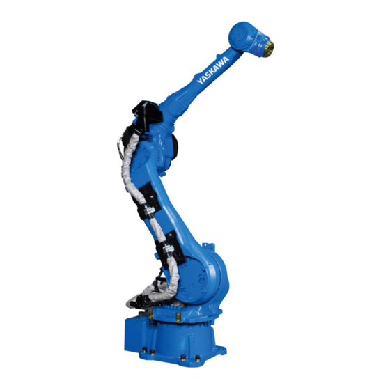
Technical data Parts and work axis label Parts designation and working axes Upper arm (U arm) Wrist flange Lower arm (L arm) Rotary head of the S-axis Robot base Robot base dimension Robot base dimensions 2 holes Ø 12 H7 8 Holes Ø... -
Page 32: Dimensions And Defined Working Area
Technical data Dimensions and defined working area 611.5 2456 1025 1369 234 234 1121 1771 1056 530 543 2061 3832 Fig. 6-1: Dimensions and defined work area P point Working area, defined with point P All dimensions in mm... - Page 33 Technical data Home position and operating range of each axis S-axis +180 L-axis U-axis R-axis B-axis T-axis -180 +360 -360...
-
Page 34: Adjustable Working Area
Technical data Adjustable working area The work area of the s-axis may be changed depending on the type of application. If any modification is necessary, please contact the local YASKAWA branch office. Item Specifications S-axis working range ± 180° (standard) ±... -
Page 35: Components For Changing The Working Area
Technical data 6.4.2 Components for Changing the Working Area If you change the working area of S-axis, the following components are required (see the following figure). Components of the S-axis limitation Screw M20 x 40 Collar 3 M6 washers S-axis working range Stop position ±180°... -
Page 36: Adjusting The S-Axis Pulse Limit
Technical data 6.4.3 Adjusting the S-Axis Pulse Limit NOTICE To change the movement range of the machine, set both the pulse limit and the angle of the mechanical S-axis limit. For altering the range of motion of S-Axis, refer to “YRC1000 GENERAL OPERATOR'S MANUAL chapter ”Softlimit setting function (Document No.: E1102000220XX01 or higher)”. -
Page 37: Stopping Angle And Time At The Emergency Stop
Technical data Stopping Angle and Time at the Emergency Stop The definition of the coastdown times is important for determining the safety distance for protective devices. The overrun time is the time that elapses from the point of time when the stop signal is triggered until the robot comes to a complete stop. -
Page 38: Stop Category 0
Technical data 6.5.1 Stop category 0 Measurement condition by category 0 • Maximum load • Maximum speed • Posture of maximum inertia Axis Overrun distance (degrees°) Overrun time (second) S-axis 20.6 0.292 L-axis 0.153 U-axis 13.48 0.185... -
Page 39: Stop Category 1
Technical data 6.5.2 Stop category 1 6.5.2.1 Stop position S-axis • 100% deflection • 66% deflection • 33% deflection... - Page 40 Technical data 6.5.2.2 Stop position L-axis • 100% deflection • 66% deflection • 33% deflection...
- Page 41 Technical data 6.5.2.3 Stop position U-axis • 100% deflection...
-
Page 42: Allowable Load For Wrist Axis And Wrist Flange
Allowable load for wrist axis and wrist flange Allowable load for wrist axis and wrist flange Wrist flange The dimensions of the wrist flange are shown in the following figure "Wrist flange". To ensure that the home position marks can be seen at all times, the tool may only be flange- mounted with the inner diameter. -
Page 43: Allowable Wrist Load
Thus, in the case when only the inertia load is applied, when the moment load is small while the inertia load is large or when the load is not applied as mass but applied as force, etc.,contact your YASKAWA representative in advance. - Page 44 Allowable load for wrist axis and wrist flange Keep the centroidal distance of the load/mass within the specifications; refer to the fig.: Moment of arm rating Moment of arm rating P point LT(mm) T-axes rotation center line B-axes rotation centre line All dimensions in mm LB(mm) P point...
-
Page 45: Maximum Capacity Load
Failure to observe this instruction may adversely affect the safety and/or performance of the robot. YASKAWA provides no guarantee against damages, malfunctions, failures, etc. caused by using any means other than the tapped holes shown in the following figure. The tightening bolts used for the mechanical parts of the manipulator must be used only to secure the mechanical parts. - Page 46 Allowable load for wrist axis and wrist flange Section Notice Up to 30 kg. (only for floor- and ceiling-mounted types)
-
Page 47: Internal Cables And Compressed Air Lines
Internal cables and compressed air lines Internal cables and compressed air lines Internal cables (4 wires 1.25 mm², 2 wires 0.75 mm², 8 wires 0.20 mm²) and air hoses are used in order to use peripheral devices (e.g. gripper). They are mounted on the upper arm as shown in the following diagram "Connector for internal cables and compressed air lines". - Page 48 Internal cables and compressed air lines Connectors for internal user I/O wiring harness and air line Connector for the internal user I/O wiring harness. Position of the main key (upper side) Connector plug for the internal cable feed through on the casing cover. Air outlet port 1 (PT3/8) Air outlet port 2 (PT3/8) Cover for fieldbus (Tube internal Ø...
- Page 49 Internal cables and compressed air lines Detailed drawing of connector ● = used ○ = not used Pins used Detailed drawing connector on casing Detailed drawing connector on base 12 11 20 19 23 22 21 The internal connections of the robot are shown in the following diagrams "Connection diagram A"...
- Page 50 Internal cables and compressed air lines When operating, be careful not to let the connector and/or the cable touch the robots body. Mating connector for internal user I/O wiring harness (straight type) U-arm part: Straight Base part: Straight...
- Page 51 Internal cables and compressed air lines Fig. 8-1: Internal connection diagram (a)
- Page 52 Internal cables and compressed air lines Fig. 8-2: Internal connection diagram (b)
-
Page 53: Maintenance And Inspection
Put up the required warning sign, e.g "Do not turn the power on!". Install a switch-on guard as prescribed. If you have any questions regarding disassembly or repair, please contact the local YASKAWA branch office. NOTICE Home position data is lost Before removing the connector of the encoder cable to perform maintenance or inspection, ... -
Page 54: Inspection Schedule
In the table of „Inspection intervals“, the inspections are divided according to three levels of requirement: • Works, carried out by trained staff. • Work carried out by staff trained by YASKAWA. • Works, carried out by YASKAWA staff. Inspections are only carried out by trained staff. NOTICE ... - Page 55 1 Trained staff 2 YASKAWA trained staff 3 YASKAWA personnel Item numbers Schedule (h) Method Operation To be per- formed by: Alignment marks Visual inspection Check alignment mark correspondence and dam- age at the zero position.
- Page 56 Item numbers Schedule (h) Method Operation To be per- formed by: Overhaul 1. The item numbers correspond to the following diagram "Inspection intervals" 2. When checking for conduction with multimeter, connect the battery to "BAT" and "OBT" of connectors on the motor side for each axis. Now remove the connectors of the encoders of the respective motor.
- Page 57 Maintenance and inspection Fig. 9-2: Inspection intervals...
-
Page 58: Note On Battery Unit
Maintenance and inspection Note on battery unit NOTICE The absolute encoder data will be lost Removing the battery unit, make sure you not to remove the plug from circuit board. The battery units are installed as shown in picture "The location of the battery unit". If battery alarm occuring in the robot controller, battery unit has to be changed in the following form. - Page 59 Maintenance and inspection 3. Remove the connector from the “IN” port of the multi-port connector. Connect the lead for battery replacement to the “IN” port of the multi-port connector. 4. Connect the battery pack for backup to the lead for battery replacement. 5.
- Page 60 Maintenance and inspection Fig. 9-3: Battery unit location Battery unit for B- and T-axes Battery unit for S- and L-axes Battery unit for U- and R-axes 2 screws M4 x 8 (Tightening torque 2.8 Nm) Cable tie Cover for S- and L-axis Protective tube 3 screws M4 x 8 (Tightening torque 2.8 Nm) Multi-port connector (board)
-
Page 61: Multiple Connection
Maintenance and inspection 9.2.2 Multiple connection The multi-port connector includes 4 terminals. • 2 connections for the motor • 2 connections for the cable harness NOTICE The absolute encoder data will be lost Absolute encoder data are lost if you remove the plug between engine and multi-port connector during battery replacement. -
Page 62: Home Position Check
There are alignment marks on each axis to check the home position (Refer to figure “Alignment mark check” below). With those alignment marks, check for home position deviation on regular basis. When home position is disappeared or deviated, contact YASKAWA representative. Alignment mark check S-axis alignment mark... -
Page 63: Seeped Oil Check
Maintenance and inspection Seeped oil check Check for seeped oil and/or oil spot periodically. Especially the parts indicated in figure “Inspection parts for seeped oil check” must be inspected carefully. Wipe off seeped oil or oil spot with a cloth before use. Fig. -
Page 64: Axis Motors
For these procedures of each axis, refer to figure “Positions of grease-leakage detection hole". When grease leakage is detected, contact YASKAWA representative. Positions of grease-leakage detection hole Grease-leakage detection hole... -
Page 65: Refill/Replace Grease
Maintenance and inspection Refill/Replace grease. Make sure to follow the instructions. If the following instructions are not followed, it might cause damage to motor or gear. CAUTION! Burns from heated grease The grease may be under pressure and may spray out of the threaded hole when opening the threaded hole. - Page 66 Maintenance and inspection Designation Tightening torque (Nm) 0.15 PT1/8 PT3/8 16.5 Tab. 9-2: Tightening torque of sealing plug 1. Remove plug from grease exhaust port (OUT) and grease inlet (IN) port. 2. Mount the lubricating nipple to the grease inlet opening. 3.
-
Page 67: Grease Filling The Main Axes
Maintenance and inspection 9.6.1 Grease filling the main axes Figure the axes S-axis gear PT3/8 Moly White Grease RE No.00 Moly White RE No.00 Grease PT1/4 AIR1 AIR2 L-axis gear PT3/8 PT3/8 Moly White Grease RE No.00 Moly White Grease RE No.00 U-axis gear PT3/8... -
Page 68: Grease Filling The Wrist Axes
Maintenance and inspection 9.6.2 Grease filling the wrist axes Figure the axes R-axis gear PT3/8 Moly White Grease RE No.00 PT1/8 Moly White Grease RE No.00 B-axis gear PT1/8 PT1/8 Moly White Grease RE No.00 Grease inlet opening Grease outlet opening 1. -
Page 69: 10 Recommended Spare Parts List
It is recommended to keep in stock parts and components in the following table as spare parts. Product performance cannot be guaranteed when using spare parts from any company other than YASKAWA. NOTICE Please contact your YASKAWA branch office if you need spare or replacement parts. Part List robot Designation Type Material no. - Page 70 Recommended spare parts list Part List robot Designation Type Material no. U-axis: Gear HW0387753-A 144090 Pinion HW0313740-1 146393 Motor SGM7G-13APK-YR1* 192010 Lead wire for signal HW1372597-AF 194188 Shaft seal input-pinion Y426012.5 126684 O-Ring gear G195 173937 R-axis: Gear HW0387754-A 144091 Motor SGM7G-09APK-YR1* 186828...
- Page 71 Recommended spare parts list Part List robot Designation Type Material no. T-axis: Gear HW0389043-A 144093 Motor SGM7G-09APK-YR1* 186828 Lead wire for signal HW1372597-AI 194191 Out/Input conical gear drive set HW0313630-1/ 176828 HW0313631-1 Shim input gear 10048 (0.05 mm) HW0412696-1 184485 Shim input gear 10047 (0.05 mm) HW9405885-1 121010...
- Page 72 Recommended spare parts list Part List robot controller Designation Type Material Key Sheet/General AKS-000E 183101 Key Sheet/ARC AKS-001E 184842 Key Sheet/Handling AKS-002E 186795 DC24V fuse for I/O 02173.15P 3,15A, 250V 103985 Control power supply fuse (2 pieces) FNQ-10 10A, 500VAC 186796 Encoder power supply fuse HM10 1A, 250V...
-
Page 73: 11 Parts Lists
Parts lists 11 Parts lists 11.1 S-axis unit 1035 1013 1036 1014 1010 1002 1011 1036 1009 1021 1007 1022 1005 1008 1003 1001 1004 1012 Fig. 11-1: S-axis unit... - Page 74 Parts lists Parts list S-axis unit DWG No. Name Pcs. 1001 HW1382898-A Gear 1002 SGM7G-30APK-YR1* Motor 1003 HW9404486-1 Shaft 1004 HW0400405-3 Stopper 1005 6310 Bearing 1007 M8 x 45 Screw 1008 2H-8 Washer 1009 HW0102237-4 S-head 1010 M12 x 45 Screw 1011 2H-12...
-
Page 75: L-Axis Unit
Parts lists 11.2 L-axis unit 2021 2022 2001 2027 2024 2023 2018 2027 2025 2019 2010 2025 2027 2011 2020 2012 2014 2013 2026 2015 2016 1009 2005 2004 2026 2003 2009 2008 2002 2007 2006 Fig. 11-2: L-axis unit Parts list L-axis unit DWG No. - Page 76 Parts lists Parts list L-axis unit DWG No. Name Pcs. 2010 HW9481343-A Shaft 2011 HW9482771-A Pinion 2012 HW9405902-1 Pipe 2013 M8 x 130 Screw 2014 2L-8 Washer 2015 Washer 2016 G270 O-ring 2018 HW0314011-1 Motor base 2019 HW0312815-2 Shaft 2020 HW9482447-A Oil seal 2021...
-
Page 77: U-Axis Drive
Parts lists 11.3 U-axis drive 5017 5007 5027 5028 2002 5015 5014 5002 5004 5003 5022 5013 5012 5026 5024 5025 5023 5001 5019 5005 5020 5011 5016 5006 5021 5018 5008 5009 5010 Fig. 11-3: U-axis unit Parts list U-axis unit DWG No. - Page 78 Parts lists Parts list U-axis unit DWG No. Name Pcs. 5003 M6 x 55 Screw 5004 2L-6 Washer 5005 M8 x 55 Screw 5006 2H-8 Washer 5007 HW0387753-A Gear 5008 HW0313740-1 Pinion 5009 HW8411125-3 Washer 5010 M6 x 115 Screw 5011 2L-6 Washer...
-
Page 79: R- B-, And T-Axes Drive
Parts lists 11.4 R- B-, and T-axes drive 7018 7006 7051 7020 7024 7016 7045 7019 7025 7001 7050 7033 7044 7032 7029 7031 7028 7013 7037 7037 7007 7036 7012 7040 7007 7048 7041 7014 7003 7022 7023 7031 7032 7021 7046... - Page 80 Parts lists Parts list RBT-axis unit DWG No. Name Pcs. 7004 TC20367 *FKM* Oil seal 7005 ISTW-17 Retaining ring 7006 HR32913J Bearing 7007 HR32005XJ Bearing 7008 HR32909J Bearing 7009 6003 Bearing 7010 HW0313628-1 Pinion 7011 HW0313627-1 Pinion 7012 HW0313629-1 Pinion 7013 HW0312826-1 Pinion...
- Page 81 Parts lists Parts list RBT-axis unit DWG No. Name Pcs. 7044 M6 x 35 Screw 7045 M8 x 30 Screw 7046 M8 x 25 Screw 7047 2H-8 Washer 7048 M8 x 20 Screw 7049 M4 x 6 Screw 7050 2L-6 Washer 7051 2L-8...
-
Page 82: Wrist Unit
Parts lists 11.5 Wrist unit 10115 10058 10015 10093 10094 10016 10095 10096 10005 10114 10115 10113 10060 10040 10039 10039 10005 10055 10013 10014 10039 10008 10057 10033 10007 10022 10039 10053 10047 10091 10048 10002 10090 10082 10104 10035 10101 10112... - Page 83 Parts lists Parts list Wrist unit DWG No. Name Pcs. 10004 HW9405445-1 10005 HW9405881-1 10006 HW9405882-1 10007 O-ring 10008 AE3092E2 Oil seal 10009 SC15247-FKM Oil seal 10010 SC39528-FKM Oil seal 10011 HW9405883-1 Collar 10012 HW9381667-A Pinion 10013 HW9381668-A Pinion 10014 HW9381669-A Pinion 10015...
- Page 84 Parts lists Parts list Wrist unit DWG No. Name Pcs. 10055 HW9302630-3 Housing 10056 HW0102233-1 U-arm 10057 HW0102491-1 Wrist 10058 HW0201226-1 Cover 10059 HW0414884-1 Cover 10060 HW0412694-* Shim 10068 HW0412683-* Shim 10075 HW0412695-* Shim 10082 HW0412696-* Shim 10090 M8 x 85 Screw 10091 2L-8...
- Page 85 Parts lists...
- Page 86 Rosh Ha’ayin +972-3-9004114 ROBOPLAN Lda YASKAWA Benelux B.V. Aveiro +351-234 943 900 Son +31-40-2895500 RO Sam Robotics srl YASKAWA Polska Sp. z o.o. Timisoara +40-720-279-866 Wrocław +48-71-7928670 RO MPL Automation S.R.L. RUS YASKAWA Nordic AB Satu Mare +40 (0) 261 750 741...
Need help?
Do you have a question about the YR-1-06VX50-A00 and is the answer not in the manual?
Questions and answers