Table of Contents
Advertisement
Quick Links
Advertisement
Table of Contents

Related Manuals for YASKAWA MPL500-J00


Summary of Contents for YASKAWA MPL500-J00
- Page 1 ROBOTICS MPL500-J00 YR-MPL0500-J00 Operating and Maintenance Manual...
- Page 2 This documentation (or parts of it) must not be reproduced or made available to third parties without the express approval of YASKAWA Europe "Robotics Division GmbH”. We have checked the content of this publication for compliance with the hardware described.
-
Page 3: Table Of Contents
Table of contents Table of contents General..............5 Notes for safe operation . - Page 4 Table of contents Maximum load of the S-axis ..........39 Optimal robot performance .
-
Page 5: General
Indicates important background information and application advice. Frequently used terms The YASKAWA robot is a product of YASKAWA Electric Corporation GmbH. The robot is normally supplied with the robot controller, programming pendant, and robot cable. The terms are designated as follows in this manual:... -
Page 6: Target Group
For optimal use of our products, we recommend our customers to take part in a training session at the YASKAWA Academy. For more detailed information on the training programs, please visit www.yaskawa.eu.com or directly get in touch with your YASKAWA branch office. -
Page 7: About This Manual
If your copy of the operating and maintenance instructions is damaged or lost, please contact the local YASKAWA branch office to order a new copy. The official branch offices are listed on the last page. Please mention the manual number in your order. -
Page 8: Safety
General Safety START HOLD REMOTE TEACH PLAY EDIT DISPLAY UTILITY JOB CONTENT TEST01 S:0000 CONTROL GROUP:R1 TOOL: 0000 0001 SET B000 1 0002 SET B001 0 0003 MOVJ VJ=80.00 0004 MOVJ VJ=80.00 0005 DOUT OT#(10) ON 0006 TIMER T=3.00 0007 MOVJ VJ=80.00 0008 MOVJ VJ=100.00... -
Page 9: Signal Output For Motor Protection
General WARNING! Death or injury because of danger of crushing Before you release the emergency stop button (see Fig. 1-4: "Release of emergency stop button by turning") note the following: Make sure that there is no one within the maximum working range of the robot. ... - Page 10 General During high speed continuous operation, the temperature may rise abruptly depending upon the ambient temperature and the operation pattern, so it is necessary to promptly detect a warning. A warning message is output as a dedicated output signal, so it is recommended that you monitor it on the system side as a warning signal for the sake of safety.Refer to Concurrent I/O (E1102000155XX01* or higher) for details on the signal output.
-
Page 11: Manufacturer
General Manufacturer Address: YASKAWA ELECTRIC CORPORATION 2-1 KUROSAKISHIROISHI YAHATANISHI-KU KITAKYUSHU JAPAN 1.10 Authorized representative Address: YASKAWA Europe GmbH Robotics Division Yaskawastr. 1 85391 Allershausen Germany... -
Page 12: Supply
Supply Supply Checking the scope of delivery The standard delivery includes the following items: Fig. 2-1: Scope of delivery Programming pendant Assembly instruction Robot controller Cable Robot... -
Page 13: Position Type Plate
2-1 SHIROISHI KUROSAKI, YAHATANISHILU KITAKYUSYU, JAPAN YASKAWA Europe „Robotics Division“ GmbH Yaskawastr. 1, D-85391 Allershausen Fig. 2-2: Position type plate NOTICE Please contact the local YASKAWA branch office if the serial numbers do not match the information on the delivery note. -
Page 14: Transportation
Transportation Transportation CAUTION! Personal injury or material damage The system consists of precision components. Failure to observe this caution may adversely affect performance. Crane and forklift trucks must be performed only by authorised personnel. The same applies to the application of loops. ... -
Page 15: Using A Crane
Transportation 3.1.1 Using a crane Adequate load handling devices must be used to transport the robot. Make sure that the robot is lifted as shown in the diagram "Transport by crane". Fig. 3-1: Transport with crane 3.1.2 Using a forklift If the robot is transported using a forklift, it should be fixed on a pallet with transport securing devices and shipping bolts. - Page 16 Transportation • The shipping brackets and bolts are painted yellow. Fig. 3-2: Position of shipping bolts Position Screw type Screw M20 (12.9) B and C Screw M10 (12.9)
-
Page 17: Installation
Installation Installation CAUTION! Personal injury and damage to property The following precautions must be taken. Check that the robot controller is complete and not damaged. Do not put into operation a robot controller that is damaged or incomplete. ... -
Page 18: Ambient Conditions And Installation Location
Installation Ambient conditions and installation location When installing a robot, it is necessary to satisfy the undermentioned environmental conditions: • Ambient temperature: From 0°C to +45°C. • Air humidity: 20% to 80% relative humidity (non-condensing). • Free of corrosive gases, liquids, or explosive gases. No water, oil or dust and free from excessive electrical noise (plasma). - Page 19 Installation 12 x Ø26 8 x M20 8 x M16 1100 1200 Fig. 4-2: Base plate When the Manipulator is Mounted Directly on the Floor The floor should be strong enough to support the robot. Prepare a solid basis of sufficient thickness that is able to withstand the maximum stress of the robot.
- Page 20 Installation Direction of move- Horizontal Vertical ment Force F Moment M Force F Torque M Emergency stop 12740 N 39200 Nm 69580 N 88200 Nm (Stop category 0) Acceleration/Decelera- 5880 N 11760 Nm 34300 N 26460 Nm tion (Stop category 1) Tab.
-
Page 21: Wiring
Wiring Wiring DANGER! Danger to life due to electric shock, risk of fire due to short circuit. Wiring must be performed by authorized or certified personnel. Follow the instructions given below before wiring. Make sure that the earthing resistance does not exceed 0.1 Ω. ... -
Page 22: Cable Connections
Robot Serial No. YASKAWA ELECTRIC CORPORATION 2-1 SHIROISHI KUROSAKI, YAHATANISHILU KITAKYUSYU, JAPAN YASKAWA Europe „Robotics Division“ GmbH Yaskawastr. 1, D-85391 Allershausen Fig. 5-1: Connecting the robot system Two cables are delivered with the robot (refer to Fig. 5-2: "Robot cable"). -
Page 23: Connecting The Robot
Wiring 5.2.1 Connecting the robot 1. Check the encoder cable (1BC) and the power cable (2BC). 2. Connect the encoder cable (1BC) to the connector plate of the robot. 3. Connect the power cable(2BC) to the connector plate of the robot. Make sure that you hear each locking clip snap into place (clicking sound). -
Page 24: Connection Of The Robot Controller
Wiring 5.2.2 Connection of the robot controller Attach the robot cables in the following order. 1. Connect the encoder cable (1BC) X11 at X-1 connection to the robot controller. 2. Connect the power cable (2BC) X21 at X-2 connection to the robot controller. Make sure that you hear the locking clips snap into place (clicking sound). -
Page 25: Connecting The Programming Pendant
Do not open the door Date/Signature with power ON. Type ERDR- Robot Type Robot Order No. Robot Serial No. YASKAWA Electric corporation 2-1 Kurosaki Shiroishi Yahatanishi-Ku Kitakyushu-City Fukuoka 806-0004 Japan Kammerfeldstr. 1, D-85391 Allershausen NJ3053-1 CHECK ALL THE DOOR LOCKS PROPERLY. NJ3005-1 PROGRAMMING PENDANT Fig. -
Page 26: Technical Data
Technical data Technical data Type: Types of Mounting: Floor mounting Degree of freedom: 500 kg Payload: ±0.5 mm Repeatability: Power consumption: 9.5 kVA 2300 kg Weight: Working area of main axes: S-axis (turning) -180° - +180° L-axis (lower arm) -45° - +90° U-axis (upper arm)²... -
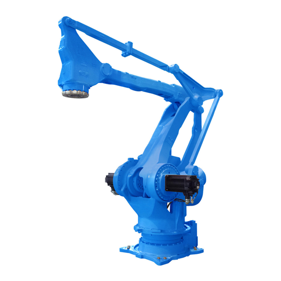
Page 27: Parts And Work Axis Label
Technical data Parts and work axis label Fig. 6-1: Part names and working axes Upper arm (U-arm) Rotating head of S-axis Wrist flange Robot base Lower arm (L-arm) Robot base dimension 220±0.1 220±0.1 320±0.1 360±0.1 Fig. 6-2: Robot base dimensions 2 holes Ø... -
Page 28: Dimensions And Defined Working Area
Technical data Dimensions and defined working area 2781 2167 1400 R1124 2204 1356 1037 3159 1300 1600 Fig. 6-3: Dimensions and defined work area P point Working area, defined with point P T point All dimensions in mm... -
Page 29: Adjustable Working Area
Technical data Adjustable working area The work area of the s-axis may be changed depending on the type of application. If any modification is necessary, please contact the local YASKAWA branch office. Item Specifications S-axis working range ± 180° (standard) *(±... -
Page 30: Components For Changing The Working Area
Technical data 6.4.1 Components for Changing the Working Area To change the working area of S-axis, the following components are required (see the following figure). Fig. 6-4: Components of the S-axis limit 3 screws M20 x 70 (strength category 12.9) and 3 x M20 washers Limit stop (HW0307574-1) -
Page 31: Instructions For Installing The Mechanical Limit
Technical data 6.4.2 Instructions for Installing the Mechanical Limit • Mount the mechanical limit of S axis so that as shown in the figure "Components of the S axis limit". • When inserting the pin in the limit, apply Loctite 242 on the screw-on surface of the pin. •... -
Page 32: Adjusting The S-Axis Pulse Limit
Technical data 6.4.3 Adjusting the S-Axis Pulse Limit If you want to change the movement range of S-axis, follow the instructions in the System Setup Manual, section: "Changing the Parameter Setting". – Pulse limit [positive direction (+) of S-axis]: SICxG400. –... - Page 33 Technical data 180° 165° 150° 135° 120° 105° 90° 75° 60° 45° 30° 15° -135° -120° -165° -150° -105° -90° -75° -60° -15° 0° -45° -30° The limit can be used on both sides. Screw Tab. 6-1: Assembly of the S-axis boundary/limitation...
-
Page 34: Stopping Angle And Time At The Emergency Stop
Technical data Stopping Angle and Time at the Emergency Stop The definition of the coastdown times is important for determining the safety distance for protective devices. The overrun time is the time that elapses from the point of time when the stop signal is triggered until the robot comes to a complete stop. -
Page 35: Stop Category 0
Technical data 6.5.1 Stop category 0 6.5.1.1 Stop position S-axis • 100% deflection • 66% deflection • 33% deflection... - Page 36 Technical data 6.5.1.2 Stop position L-axis • 100% deflection...
- Page 37 Technical data 6.5.1.3 Stop position U-axis • 100% deflection...
-
Page 38: Stop Category 1
Technical data 6.5.2 Stop category 1 6.5.2.1 Stop position S-axis • 100% deflection 6.5.2.2 Stop position L-axis • 100% deflection 6.5.2.3 Stop position U-axis • 100% deflection... -
Page 39: Allowable Load For Wrist Axis And Wrist Flange
Allowable load for wrist axis and wrist flange Allowable load for wrist axis and wrist flange Wrist flange The dimensions of the wrist flange are shown in the following figure "Wrist flange". To ensure that the home position marks can be seen at all times, the tool may only be flange- mounted with the inner diameter. -
Page 40: Allowable Wrist Load
Allowable load for wrist axis and wrist flange Allowable Wrist Load 1000 800 600 1000 400 600 800 LT (mm) W=500 kg W=450 kg W=400 kg 1000 LB (mm) Fig. 7-2: Moment of arm rating P-point B-axes rotation center line R-, T-axes rotation center line All dimensions in mm In order to facilitate the user's system applications , the peripheral equipment mounts and... - Page 41 Allowable load for wrist axis and wrist flange Application Notice Wiring and valve load Up to 500 kg for attaching load mass including wrist load. Tab. 7-1: Installation Conditions...
- Page 42 Example: In the case of the YASKAWA HP20D robot, for example, the permissible moment of inertial for the T-axis amounts to 0.25 kgm² at a permissible torque of 19.6 Nm and to 0.75 kgm² at...
-
Page 43: Internal Cables And Compressed Air Lines
Internal cables and compressed air lines Internal cables and compressed air lines Internal cables 23 wires 23 x 0.50 mm² and 5 pneumatic lines) and air hoses are used in order to use peripheral devices (e.g. gripper). They are mounted on the upper arm as shown in the following diagram "Connector for internal cables and compressed air lines". - Page 44 Internal cables and compressed air lines 2. As shown in Fig. 8-2: "Field bus cable connection", the tube for field bus cable (inner diameters: 12 mm), will beconnected by connecting the section with the S-head. Lead the field bus cable C as described below. Fig.
- Page 45 Internal cables and compressed air lines 11 12 19 20 21 22 23 Fig. 8-3: Detailed drawing of connector = used = not used Pins used Internal cables: 23 wires, 0.5 mm² The wrist part of the robot has a hollow structure for the internal user I/O wiring harness, air line, etc.
- Page 46 Internal cables and compressed air lines • To the 3BC connection for the collision sensor on the U arm. • To the 3BC connection for the collision sensor on the robot controller. Pins 7 and 8 of the respective 3BC connections on the connector plate and U arm are connected to each other.
- Page 47 Internal cables and compressed air lines Fig. 8-6: Internal connection diagram (b)
-
Page 48: Maintenance And Inspection
Put up the required warning sign, e.g "Do not turn the power on!". Install a switch-on guard as prescribed. If you have any questions regarding disassembly or repair, please contact the local YASKAWA branch office. NOTICE Home position data is lost Before removing the connector of the encoder cable to perform maintenance or inspection, ... -
Page 49: Inspection Schedule
In the table of "Inspection intervals", the inspections are divided according to three levels of requirement: • Works, carried out by trained staff. • Work carried out by staff trained by YASKAWA. • Works, carried out by YASKAWA staff. Inspections are only carried out by trained staff. NOTICE ... - Page 50 Trained staff YASKAWA trained staff YASKAWA staff Inspection intervals Item numbers Schedule (h) Checking method Operation Inspection Charge: Alignment marks Visual inspection Check alignment mark accordance and damage at the home position. External cable Visual inspection Check cable for damage.
- Page 51 Inspection intervals Item numbers Schedule (h) Checking method Operation Inspection Charge: Wire harness in the robot Visual, multimeter Check for conduction between the main connec- tor of base and intermediate connector with manually shaking the wire. Check the protection spring ...
- Page 52 1. The item numbers correspond to the following diagram "Inspection intervals" 2. If there is any grease leakage, this may mean that grease has entered the motor. This can damage the motor. If you have any questions, please contact the local YASKAWA branch office.
- Page 53 Maintenance and inspection Fig. 9-2: Inspection intervals The numbers in the above figure are equal to the numbers in the table of "Inspection intervals".
-
Page 54: Note On Battery Unit
Maintenance and inspection Note on battery unit 9.2.1 Battery pack replacement Fig. 9-3: Battery unit location (front view) 4 screws M4 Stand Power input module Fig. 9-4: Battery unit location (top view) Battery unit Circuit board The battery units are installed as shown in picture "The location of the battery unit". If battery alarm occuring in the robot controller, battery pack has to be changed in the following form. - Page 55 Maintenance and inspection 1. Turn the robot controller to the main power supply (see Fig. 9-5: "Main power switch in "switch-off" position"). WARNING High Voltage Do not open the door with power ON. Fig. 9-5: Main power switch in "switch-off" position Main power switch in "switch-off"...
- Page 56 Maintenance and inspection 7. Please remove old battery pack plug from circuit board. NOTICE Make sure that no wires are pinched when you install the battery pack and the cover plate again. 8. Please apply Teroson Plast sealing compound (material no. 143813) to thread part of screws.
-
Page 57: Battery Pack Connector (Including Warning Note)
Maintenance and inspection 9.2.2 Battery pack connector (including warning note) OBT* Fig. 9-7: Battery unit connector diagram for S-, L- and U-axes Motor Battery unit Motor power connector Plug for backup Encoder connector Before removing the encoder connector (with CAUTION label), connect the battery to the motor as shown in the following figure. -
Page 58: Refill/Replace Grease
Maintenance and inspection Refill/Replace grease. Make sure to follow the instructions. If the following instructions are not followed, it might cause damage to motor or gear. CAUTION! Burns from heated grease The grease may be under pressure and may spray out of the threaded hole when opening the threaded hole. - Page 59 Maintenance and inspection Tightening torque of sealing plug Designation Tightening torque (Nm) PT 3/8 PT 1/4 PT 1/8 PT 1/16 1. Remove plug from grease exhaust port (OUT) and grease inlet (IN) port. Example: 2. Mount the lubricating nipple to the grease inlet opening. 3.
-
Page 60: Grease Filling The Main Axes
Maintenance and inspection 9.3.1 Grease filling the main axes Figure the axes Amount of grease: S-axis gear Replenishment: 2100 cm³ / approx. 1827 g Exchange: 10400 cm³ / approx. 9048 g L-axis gear Replenishment: 460 cm³ / approx. 400 g Exchange: 2300 cm³... - Page 61 Maintenance and inspection Air outlet cap Joint...
-
Page 62: Grease Filling The Wrist Axes
Maintenance and inspection 9.3.2 Grease filling the wrist axes Grease filling the wrist axes Figure the axes Amount of grease: BT-axis gear Replenishment: 320 cm³ / approx. 278 g Exchange: 1600 cm³ / approx. 1392 g U-axis cross roller bearing Replenishment: 60 cm³... -
Page 63: Refilling The Amount Of Grease In Joints
Maintenance and inspection 9.3.3 Refilling the amount of grease in joints – Amount of grease for joints 1, 2, 3, 6: 6 cm³ / approx. 5 g) – Amount of grease for joints 4, 5, 9: 12 cm³ / approx. 10 g –... -
Page 64: Home Position Calibration
In a system with two or more Robots, the home position of all the Robots must be calibrated before starting teaching or playback. For more information, see also system setup in the manual or contact your YASKAWA branch. - Page 65 Maintenance and inspection 2. Select {HOME POSITION}. The <HOME POSITIONING> window appears. 3. Select {DISPLAY} under the menu, or select “PAGE” to display the selection window for the control group, or press [PAGE]. The pull-down menu appears. 4. Select the desired control group. 5.
- Page 66 Maintenance and inspection 6. Select {SELECT ALL AXES}. A confirmation dialog box is displayed. 7. Select {YES}. Displayed position data of all axes are registered as home position. When {NO} is selected, the registration will be canceled.
-
Page 67: Registering Individual Axes
Maintenance and inspection 9.4.2 Registering individual axes 1. Select {ROBOT} on the main menu. The sub-menu choices appear. 2. Select {HOME POSITION}. 3. Select the module to be calibrated (e.g. R1:ROBOT). Perform steps 3 and 4 which have been described in “Registering All Axes at One Time” to select the desired control group. -
Page 68: Changing The Absolute Data
Maintenance and inspection 9.4.3 Changing the absolute data To change the absolute data of the axis when home position calibration is completed, perform the following: 1. Select {ROBOT} from the main menu. 2. Select {HOME POSITION}. 3. Select the desired control group. Perform steps 3 and 4 which have been described in chapter “Registering All Axes at One Time”... -
Page 69: Clearing Absolute Data
Maintenance and inspection 9.4.4 Clearing absolute data 1. Select {ROBOT} from the main menu. 2. Select {HOME POSITION}. Perform steps 2, 3, and 4 which have been described in “Registering All Axes at One Time” to display the HOME POSITIONING window and select the desired control group. -
Page 70: Setting The Second Home Position (Check Point)
Maintenance and inspection Setting the second home position (check point) 9.5.1 Purpose of position check operation If the absolute number of rotation detected at power supply ON does not match the data stored in the absolute encoder the last time the power supply was turned off, alarm 4107 “OUT OF RANGE (ABSO DATA)”... - Page 71 Maintenance and inspection 1. Position check After the “OUT OF RANGE (ABSO DATA)” alarm occurs, move to the second home position using the axis keys and perform the position confirmation. For performing the position confirmation, refer to chapter “Procedure after the Alarm”. Playback and test runs will not function unless “CONFIRM POSITION”...
-
Page 72: Procedure For The Second Home Position Setting
Maintenance and inspection 9.5.2 Procedure for the second home position setting Apart from the “home position” of the robot, the second home position can be set up as a check point for absolute data. Use the following steps to set the specified point. NOTICE If 2 or more Robots or stations are controlled by one controller, the second home position must be set for each robot or station. - Page 73 Maintenance and inspection WARNING! Death or injury because of danger of crushing When performing the position check operation, pay careful attention to ensure the safety of the surrounding operation environment. If the „OUT OF RANGE (ABSO DATA)“ alarm occurs, • Reset the alarm.
- Page 74 Maintenance and inspection 4. Press {FWD}. TCP moves to the second home position. The robot moving speed is set as selected manual speed. 5. Select {DATA} on the menu. 6. Select {CONFIRM POSITION}. A message „Home position checked“ appears. Pulse data of the second home position and current pulse data should be compared. Automatic mode can be done if compared error is in allowed range.
-
Page 75: 10 Recommended Spare Parts List
It is recommended to keep in stock parts and components in the following table as spare parts. Product performance cannot be guaranteed when using spare parts from any company other than YASKAWA. NOTICE Please contact your YASKAWA branch office if you need spare or replacement parts. Designation Type Material no. -
Page 76: 11 Parts Lists
Parts lists 11 Parts lists 11.1 S-axis unit 1028 1029 1052 1027 1008 1007 1026 1051 1025 1016 1050 1024 1048 1023 1030 1004 1041 1004 1049 1045 1017 1018 1013 1019 1040 1054 1053 1020 1042 1055 1021 1031 1056 1043 1022... - Page 77 Parts lists Fig. 11-1: S-axis drive DWG no. Designation Piece 1001 HW0101142-1 Stand 1002 HW0402102-1 Stop 1003 HW9404486-1 Shaft 1004 2H-8 Washer 1005 M8 × 40 Screw 1006 2H-20 Washer 1007 2H-12 Washer 1008 M12 × 40 Washer 1009 HW0281280-A Gear (RV400C-35.61) 1010...
- Page 78 Parts lists DWG no. Designation Piece 1040 PT3/8 Grub screw 1041 M12 × 20 Screw 1042 ISTW-35 Circlip 1043 CIMR35-1 Adjusting washer 1044 6207ZZ Bearing 1045 IRTW-72 Circlip 1046 HW9381477-B Pinion 1047 HW9405051-1 Cover 1048 HW0307565-3 Shaft 1049 M8 × 115 Screw 1050 HW0407533-1...
-
Page 79: L-Axis Unit
Parts lists 11.2 L-axis unit 2062 2058 2002 2045 2046 2050 2057 2045 2004 2053 2044 2003 2059 2003 2021 2005 2054 2035 2022 2006 2035 2035 2043 2007 2048 2037 2035 2022 2035 2015 2061 2035 2008 2060 2047 2009 2016 2022... - Page 80 Parts lists DWG no. Designation Piece 2007 HW0315369-1 Shaft 2008 HW9482358-1 Pinion 2009 HW9481343-A Shaft 2010 HW0408806-1 Washer 2011 HW9482506-N Screw 2012 ISTW12 Circlip 2013 HW1404790-1 Washer 2014 M1 2 × 80 Screw 2015 PT3/8 Grub screw 2016 EZ0094-A0 Air filter 2017 G300 O-ring...
- Page 81 Parts lists DWG no. Designation Piece 2044 HW0406933-1 Cover 2045 2H-6 Washer 2046 M6 × 14 Screw 2047 HW0101145-2 Joint 2048 M16 × 65 Screw 2049 HW0406931-1 Cover 2050 M6 × 15 Screw 2051 HW0400012-1 5 Adjusting washer 2052 O-ring 2053 HR32011XJ Bearing...
-
Page 82: U-Axis Drive
Parts lists 11.3 U-axis drive 3032 3021 3029 3042 3035 3003 3033 3034 3003 3036 3037 3031 3035 3013 3016 3028 3055 3040 3015 3003 3056 3041 3014 3030 3032 3006 3020 3021 3054 3005 3054 3039 3022 3019 3007 3038 3038 3003... - Page 83 Parts lists DWG no. Designation Piece 3016 M6 x 6 Screw 3017 HW0101154-1 L-arm 3018 HW9403571-2 Shaft 3019 AG4059E0 Oil seal 3020 HR32016XJ Bearing 3021 2H-10 Washer 3022 M10 x 50 Screw 3023 MSTH6-10 3024 HW9403656-* Adjusting washer 3025 HW9301405-1 Cover 3026 HW1303023-1...
- Page 84 Parts lists DWG no. Designation Piece 3054 CP-30-BC-8 Sealing plug 3055 M6 x 20 Screw 3056 2H-6 Washer 3057 HW1303039-1 Spacer Tab. 11-3: U-axis drive...
-
Page 85: Wrist Unit
Parts lists 11.4 Wrist unit 4015 4014 4012 4013 4011 4007 4006 4026 4005 4004 4020 4003 4019 4051 4014 4025 4002 4024 4001 4003 4004 4005 4006 4015 4007 4016 4027 4041 4008 4017 4029 4042 4018 4010 4019 4030 4043 4009... - Page 86 Parts lists DWG no. Designation Piece 4005 2H-8 Washer 4006 M8 × 65 Screw 4007 HR32012XJ Bearing 4008 HW9404383-1 Cover 4009 LP-M5 Grub screw 4010 M8 × 25 Screw 4011 HW9404246-* Adjusting washer 4012 HW0405915-1 Cover 4013 O-ring 4014 PT1/8 Grub screw 4015 M8 x 30...
- Page 87 Parts lists DWG no. Designation Piece 4041 HW0388666-A Motor (SGMRV-13ANA-YR1*) 4042 HW0414962-1 Flywheel 4043 HW0315061-1 Shaft 4044 2H-6 Washer 4045 M6 x 65 Screw 4046 HW9405844-2 Housing 4047 HR32907J Bearing 4048 HW9405847-1 4049 M6 x 8 Screw 4050 HW03315337-1 Pinion 4051 HW1404790-1 Washer...
-
Page 88: Balancer Unit
Parts lists 11.5 Balancer unit 5022 5028 5027 5026 5025 5031 5030 5024 5013 5012 5029 5015 5022 5023 5021 5020 5019 5012 5013 5008 5014 5002 5007 5022 5010 5009 5025 5003 5028 5026 5011 5027 5011 5004 5005 5018 5006 5017... - Page 89 Parts lists DWG no. Designation Piece 5020 HW0401112-1 Flange 5021 M5 x 10 Screw 5022 2H-10 Washer 5023 M10 x 40 Screw 5024 HW0100477-1 Housing 5025 KE901107 Oil seal 5026 HW9405055-1 Shaft 5027 HR32916J Tapered roller bearing 5028 M10 x 50 Screw 5029 EZ2228B0...
- Page 90 Rosh Ha’ayin +972-3-9004114 ROBOPLAN Lda YASKAWA Benelux B.V. Aveiro +351-234 943 900 Son +31-40-2895500 RO Sam Robotics srl YASKAWA Polska Sp. z o.o. Timisoara +40-720-279-866 Wrocław +48-71-7928670 RO MPL Automation S.R.L. RUS YASKAWA Nordic AB Satu Mare +40 (0) 261 750 741...
Need help?
Do you have a question about the MPL500-J00 and is the answer not in the manual?
Questions and answers