Table of Contents
Advertisement
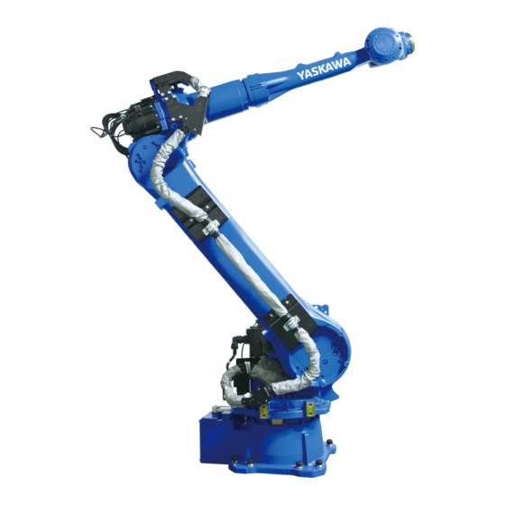
MOTOMAN-GP50,GP35L
MAINTENANCE MANUAL
TYPE:
YR-1-06VX50-A00
(MOTOMAN-GP50 STANDARD SPECIFICATION)
YR-1-06VXL35-A00
(MOTOMAN-GP35L STANDARD SPECIFICATION)
Procedures described in this maintenance manual should be carried out by the person who took
the maintenance-relevant trainings offered by YASKAWA.
Upon receipt of the product and prior to initial operation, read these instructions thoroughly, and
retain for future reference.
MOTOMAN INSTRUCTIONS
MOTOMAN-GP50,GP35L INSTRUCTIONS
YRC1000 INSTRUCTIONS
YRC1000 OPERATOR'S MANUAL (GENERAL) (SUBJECT SPECIFIC)
YRC1000 MAINTENANCE MANUAL
YRC1000 ALARM CODES (MAJOR ALARMS) (MINOR ALARMS)
The YRC1000 operator's manual above corresponds to specific usage. Be sure to use the appropriate manual.
The YRC1000 operator's manual above consists of "GENERAL" and "SUBJECT SPECIFIC".
The YRC1000 alarm codes above consists of "MAJOR ALARMS" and "MINOR ALARMS".
182738-1CD
0
MANUAL NO.
HW1484673
1/109
Advertisement
Table of Contents


Need help?
Do you have a question about the Motoman GP50 and is the answer not in the manual?
Questions and answers