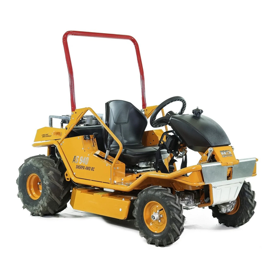
AS MOTOR AS 940 Sherpa 4WD RC Operator's Manual
Rough terrain mower
Hide thumbs
Also See for AS 940 Sherpa 4WD RC:
- Operating instructions manual (56 pages) ,
- Workshop manual (106 pages)

Related Manuals for AS MOTOR AS 940 Sherpa 4WD RC


Summary of Contents for AS MOTOR AS 940 Sherpa 4WD RC
- Page 1 Operator's Manual Rough Terrain Mower AS 940 Sherpa 4WD RC From serial number: 031717070001 Issued: 23.08.2017, V1.1 (not California) en-us, Translation of the Original Operator's Manual...
-
Page 2: Notes On The Operator's Manual
Any other use exceeding this purpose is inadmissible. In this operator’s manual, for AS 940 Sherpa 4WD RC the Observe the instructions chapter for Maintenance. Otherwise, term “device” is being used. -
Page 3: Table Of Contents
Contents Contents Check oil level.............. Notes on the operator’s manual......... Verwendeter Kraftstoff..........Contact ................. Fueling................Device data..............Checking and changing the battery on the Remote Control Transmitter............Intended use..............Sitzposition einstellen........... Explanation of the symbols........Sitzfederung einstellen..........Warnings..............Bügel aufklappen............Symbols in the instructions........... - Page 4 Contents Checking the spark plugs..........Maintaining the air filter..........Checking and charging the battery....... Hydrostat-Getriebe............Zusammenbau ............. Scope of delivery............Unpacking..............Assembly..............Lagerung ..............Aufbewahrung.............. Längere Einlagerung............ Restarting..............Spare parts..............Reordering labels............Wear parts..............Tires................Disposal................ Garantie................ Possible faults ............. Error codes..............
-
Page 5: Explanation Of The Symbols
Explanation of the symbols dummy Inhaltsverzeichnis Symbols in the instructions Explanation of the symbols The device is only as safe as its user. Carelessness, negli- gence or an operating error could result in severe injuries or death. Warnings In this operator's manual, the following symbols are used to In these operating instructions, warning instructions are denote special dangers. -
Page 6: Position Of The Safety Signs On The Device
Position of the safety signs on the device Position of the safety signs on the device The following signs are attached to the device to provide a reminder that during use of the device, you will have to be careful and attentive. -
Page 7: Description Of The Safety Signs On The Device
Description of the safety signs on the device B G00014806 Description of the safety signs on the device A G00014774 + G00014773 Fig. 1: Fig. 3: Risk of injury. Keep your hands and feet away. C G00014776 Fig. 2: Read and understand the operator’s manual. Operate the machine only when the safety devices, screens and safety installations are in place and properly functioning. - Page 8 Description of the safety signs on the device D G00014845 G G00014778 The quickly rotating blades can cause life-threat- Risk of injury! ening injuries or major property damage! Object can be ejected. Make sure to especially keep hands and feet Make sure that nobody is in the danger area of away from the blades when the device is in oper- the device.
- Page 9 Description of the safety signs on the device I G00014799 O G00014842 Risk of tipping. In remote control mode (RC), do not pause below the device on slopes. L G00014804 Risk of injury due to rotating parts. Keep your hands away from rotating parts. J G00014798 Fig. 5: Warning sign of the engine manufacturer on the engine.
- Page 10 Description of the safety signs on the device M G00014796 F G00014747 Do not clean the device with water spray or a high-pressure cleaner. P G00014781 Fig. 7: Batteries can be dangerous. Keep children away. Read the information in the operator’s man- ual on the battery.
-
Page 11: Safety Instructions
Safety instructions Safe handling of fuel Safety instructions Fuel is toxic and highly flammable. There is a burn and explo- sion hazard! Prior to starting Keep fuel away from ignition sources and do not smoke dur- For your safety, read these operator’s manual carefully. Fa- ing handling. -
Page 12: Check The Device Prior To Use
Safety instructions Check the device prior to use Additional danger area in the RC mode Prior to each use, check the blade, protection skirt, ejection Dangerous situations can result from unintended steering or rubber, drive and fastening parts, cables and cable connec- driving movements. -
Page 13: Fire Hazard
Safety instructions Fire hazard Use caution during operation Parts of the device can become extremely hot during opera- Danger of injury during motor start tion and this may cause fire. The motor must not be started: – Carry a sufficient amount of extinguishing material. –... -
Page 14: Prior To Mowing
Safety instructions Prior to mowing Use caution when mowing Personal protective measures Risk of injury Risk of injury caused by ejected objects. Never mow when During mowing, always wear safety shoes with persons, children, pets or objects are in the danger area. good grip and long trousers. -
Page 15: Driving On Slopes
Safety instructions Driving on slopes When the wheels encounter obstacles such as roots, branches, rocks, mounds etc., the device can tilt or slip. If the device, while in use, stops on slopes or the engine cuts – Only drive on terrain that it free of obstacles and when you out, the device can roll away. -
Page 16: Nach Dem Arbeiten
Safety instructions Nach dem Arbeiten After mowing, always close the fuel valve. Before you leave the device, wait until the engine stops com- pletely. Press the start-stop switch on the Remote Control Remote Control Transmitter and remove the key. Then switch off the main switch. -
Page 17: Gerätebeschreibung
Gerätebeschreibung Gerätebeschreibung 9 10 11 12 1 Gearbox fan 2 Muffler grid 3 Transport deposit 4 Antenna 5 Receiver with LED display 6 Ventilation grid 7 Oil surge tank 8 Folding bar 9 Emergency stop 10 Status indicator (on both the right side and the left side of the device) 11 Power socket 12 Fuse circuit (see Technical data) -
Page 18: Control Elements On The Device
Control elements on the device Fuel valve (3) Control elements on the device You can order a set of labels for the control elements under 1: Open number G06980401. 2: Closed Frontbereich Remote Control Transmitter holder (4) Insert the Remote Control Transmitter into the Remote Con- trol Transmitter holder Fig. 9: Fußbremse/Parkbremse (1) -
Page 19: Control Lever On The Seat
Control elements on the device Betriebsstundenzähler (3) Control lever on the seat Die Betriebsstunden werden gezählt, sobald der Motor läuft. Display: – bei laufendem Motor: Engine speed – bei stillstehendem Motor: Operating hours Schnitthöhenanzeige (4) Die oberste Position (0) ist die Transport- stellung. -
Page 20: Rear Part
Control elements on the device Moving the device without drive (5) Rear part To push the mower without motor drive, unlock the drive at the rear of the device and release the parking brake. Fig. 11: Status indicators (1) The status indicators on the device flash when the blade is engaged. -
Page 21: Folding Bar
Control elements on the device Selection lever operating moves (6) Folding bar Fig. 14: Read the selection lever position at the stickers to the left and right of the selection lever. MC operating mode (ride-on mode): Putting down the folding bar Pull out the lever (1). Put down the folding bar (2). -
Page 22: Control Elements On The Remote Control Transmitter
Control elements on the Remote Control Transmitter Control elements on the Remote Control Transmitter Max. Driving Speed Left Right Oil Pressure Blade On Steering Trim. Cut. Height Diff. Lock Blade Engine Start Transp. Pos. On/Horn Freq. Change Down The Remote Control Transmitter come with 2 keys (A) for the –... - Page 23 Control elements on the Remote Control Transmitter Drive forward Joystick Drive backward: Steering to the left Joystick Left Steering to the right Right Horn/acknowledge Button RC+MC On/Horn Engine start Button RC+MC Engine Start Differential lock off Toggle switch Differential lock on Diff.
-
Page 24: Acoustic Signals
Acoustic signals Carrying the Remote Control Transmitter Display on the Remote Control Transmitter Frequency: After radio contact has been estab- lished between Remote Control Transmitter and Receiver, the frequency number is briefly dis- played. Remote Control Transmitter in operation: Red dot jumps as back and forth. -
Page 25: Operating Modes
Operating modes Checking the slope Description LED 1 LED 2 LED 3 Other error (undefined) Lights up red Warning sources or flashes Driving on slopes is dangerous. There is a tilting and slip- ping hazard. Operating modes ► Observe the safety instructions regarding driving on slopes and the danger area. -
Page 26: Differential Lock
Differential lock Differential lock Vor dem Starten Warning Check oil level Danger of injury when driving turns When turns are driven while the differential lock is acti- Notice vated, the turning circle is increased. Incorrect oil level can damage the engine. ►... -
Page 27: Sitzposition Einstellen
Vor dem Starten – The device cannot be operated any longer, also in the MC The seat suspension should be set as soft as possible to mode. keep it from going coil-bound during normal operation. The current setting is displayed on the scale on the seat. Checking the battery If the seat suspension goes coil-bound during normal opera- tion, turn the handwheel clockwise. -
Page 28: Switching On Receiver And Remote Control Transmitter
Switching on receiver and Remote Control Transmitter Changing the radio frequency Switching on receiver and Remote Control Transmitter you must switch on the receiver first, no matter in which oper- ating mode you want to work. 1. Switch on the main switch on the device. ð... -
Page 29: Steering In The Mc Mode
Working in the MC mode ð Engine is started. 3. To stop move the drive lever slowly to neutral position or step on the foot brake. ð The oil control light (13) on the Remote Control Trans- mitter goes out. Reversing 3. -
Page 30: Moving Blade To Transport Position
Working in the MC mode – The blade is not in transport position. Move blade to transport position: Transp. Pos. Press button (9). 1. Briefly press the button (9)to move the blade to transport position. ð The blade is immediately disengaged. ð The blade is moved to transport position. Activating the differential lock in the MC mode To activate the differential lock, press the left pedal all the... -
Page 31: Switching From The Mc Mode To The Rc Mode
Working in the MC mode Emergency stop in the MC mode Warning After an Emergency stop on steep terrain, the device can roll away. ► Immediately activate the parking brake to prevent the device from rolling away. Causes of the Emergency stop –... -
Page 32: Practicing The Rc Mode
Practicing the RC mode 7. The blade is disengaged in case of an Emergency stop. 2. Press the button “Engine start” (5) on the Remote Control However, the toggle switch “Blade clutch” (7) remains in Transmitter. the position that was last selected. Therefore, set the tog- ð... -
Page 33: Driving In The Rc Mode
Working in the RC mode Driving in the RC mode Setting the cutting height Warning Risk of injury during driving forward and in reverse. ► Make sure no other persons stand in front of or behind the device and that your path is clear of obstacles. ►... -
Page 34: Moving Blade To Transport Position
Working in the RC mode Fig. 30: Move blade to transport position: Transp. Pos. Fig. 29: Press button (9). Blade On Engaging blade: Set toggle switch (7) to “On”. Disengaging the blade: Set toggle switch (7) to “Off”. 1. Briefly press the button (9)to move the blade to transport position. -
Page 35: Switching From The Rc Mode To The Mc Mode
Working in the RC mode Switching from the RC mode to the MC Warning mode Danger of poisoning due to exhaust gases ► Do not operate the engine in a closed or insufficiently Warning ventilated room. Risk of injury due to rotating blade. ►... -
Page 36: Transport
Transport Procedure after an Emergency stop Notice Risk of damage due to incorrect fastening of straps. ► Fasten the straps only at the points shown in the figure. ► Do not overtighten the straps. Put the device in front of the ramps and make sure that the ramps –... -
Page 37: Unloading The Device
Moving the device without drive Unloading the device Towing 1. Slacken the transport attachments. If the engine cannot be started again, the device must be towed. 2. Carefully drive the device over the ramps off the loading area. 1. While using the brakes, let the device roll to terrain that is less steep. -
Page 38: Maintenance
Maintenance Let the device cool down for at least 20 minutes. Maintenance Close the fuel valve. For maintenance and cleaning work, always wear safety Press the start-stop switch on the Remote Control trans- gloves and safety glasses. mitter and remove the key. Switch off the main switch. -
Page 39: Yearly Or Every 50 H By The Authorized Service Center
Maintenance Release the drive lever Does the device stop when the lever is in neutral posi- tion (parking brake)? Does the lever in MC mode move to neutral position when the brake pedal is activated? Does the drive lever in the MC mode move to neutral position when the driver leaves the seat? Bowden cables Check for proper function and ease of movement. -
Page 40: Gerät Reinigen
Maintenance V-belt Are the belts tensioned correctly, without fissures, and in good condition? Bowden cables Check for proper function and ease of movement. Acceleration lever Check for proper function. Chassis and protective Check for rust and fissures and check the welding devices seams. -
Page 41: Checking The Safety Functions
Maintenance Checking the drive lever Seat contact switch 1. Turn the rotary knob “maximum speed” to rabbit. 1. Select MC operating mode. 2. Press the left joystick forward. 2. Insert the Remote Control Transmitter into the Remote Control Transmitter holder. ð... -
Page 42: Check Parking Brake
Maintenance 3. Try to switch on the Remote Control Transmitter. Messer prüfen ð The Remote Control Transmitter should not turn on with- out the key. Warning Wear or damage to the blades and the fastening elements Checking the transport position of the blade can result in the blades or the fastening elements coming 1. -
Page 43: Checking The Blade Brake Clutch
Maintenance Cutting blades (5) Motor warten The cutting blades should move easily. To ensure this, al- ways keep the pivotal point (3) clean. Never mow when the Caution cutting blades are stuck. If the speed is set too high, objects can be ejected. The Caution! To prevent imbalance, replace or reverse the cut- engine can be damaged and a higher lever of noise pollu- ting blades in pairs only! -
Page 44: Motorölstand Prüfen
Maintenance Motorölstand prüfen Warning Explosion hazard Notice Explosive gases are generated when the battery is Incorrect oil level can damage the engine. charged. An explosion of the battery can result in injuries ► Prior to each use, check the engine oil level. and blindness. -
Page 45: Hydrostat-Getriebe
Zusammenbau 6. Connect the black cable (-). 3. Insert the batteries into the Remote Control Transmitter (see Checking and changing the battery). 4. Attach the belt to the Remote Control Transmitter. Hydrostat-Getriebe 5. Remove the spare key and keep it in a safe place. Warning Assembly Risk of injury due to high pressure (up to 5945 psi /... -
Page 46: Längere Einlagerung
Spare parts Also observe the information regarding storage in the opera- Blades, cutting blades, cutter bars, blade bolts, sliding plates, tor’s manual of the engine manufacturer. V-belt, chains, Bowden cables, starter ropes, pressure plates, air filters, spark plugs, disk springs, lock washers, fuses, disks, thrust plates, pressure disks, protection skirts, impact Längere Einlagerung protection, wheels, tires. -
Page 47: Possible Faults
Possible faults Possible faults If a fault occurs, it is recommended to first switch off the Remote Control Transmitter using the start-stop switch and the device using the main switch. Wait 10 seconds and restart the device. If required, also change the frequency (see Selecting radio fre- quency [} 28]). - Page 48 Possible faults Air filter is dirty. Maintain air filter (see Maintenance). Spark plugs are dirty, damaged, Clean spark plugs and check electrode or incorrect electrode gap. gap (see Maintenance). Replace spark plugs if necessary. Housing of the mower is See Maintenance. jammed.
- Page 49 Possible faults Engine is smoking Air filter is dirty or drenched with Maintain or replace air filter (see Mainte- oil. nance). Oil level is too high. Have authorized service center lower the oil level up to the marking. Engine gets hot Ventilation grid is dirty.
- Page 50 Possible faults Emergency stop dur- Selection lever operating mode Flip the selection lever of the operating ing changing of the is not completely flipped over. mode all the way. operating mode (MC Remote Control Transmitter in Remove the Remote Control Transmitter to RC) Remote Control Transmitter from the Remote Control Transmitter...
-
Page 51: Error Codes
Possible faults Error codes When the control detects an error, an error code is displayed. The following table lists the most frequent error codes. Contact an authorized service center when an error code is displayed that you cannot find in this table. Display Designation Reasons... - Page 52 Possible faults Display Designation Reasons Remedy Microswitch transport posi- Fuse no. 5 (10 A) has blown. Eliminate cause of fuse trigger and replace tion does not switch fuse. Fuses nos. 1-3 (10 A) have blown. Eliminate cause of fuse trigger and replace fuse.
- Page 53 Possible faults Display Designation Reasons Remedy Radio interference due to other Remote Switch off Remote Control Transmitter and Control Transmitters (radio equipment, receiver, restart after 10 seconds. garage door opener, vehicle key). Switch the radio channel. Increase the distance to the disturbance source.
-
Page 54: Technical Specifications
Technical specifications Technical specifications Type AS 940 Sherpa 4WD RC Range of application (temperature) 32 – 86 °F (0 - 30 °C) For temperatures below 41 °F (5 °C), observe the engine manu- facturer's information regarding the engine oil. Engine, type Two cylinder four stroke engine Manufacturer Briggs & Stratton... - Page 55 Technical specifications The fuses are next to the power socket. Rating Designation Supplied Main fuse 1 Receiver Main fuse 2 Receiver Main fuse 3 Receiver Fuse controller generator Controller generator Fuse safety switch Emergency Stop switch Seat contact switch Monitoring blade clutch Monitoring cutting height Fuse main switch Main switch power socket...
Need help?
Do you have a question about the AS 940 Sherpa 4WD RC and is the answer not in the manual?
Questions and answers