
Related Manuals for AS MOTOR Allmaher AS 63 2T


Summary of Contents for AS MOTOR Allmaher AS 63 2T
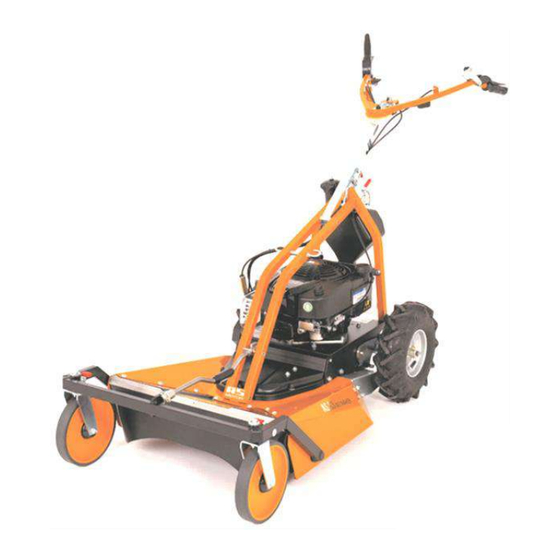
- Page 1 WORKSHOP MANUAL 01/2021 EN AS-MOTOR Allmäher ® AS 63 2T AS 63 4T B&S AS 63 4T Honda AS 62 4T B&S Service Information Adjustment, maintenance and repair instructions www.as-motor.de...
-
Page 2: Table Of Contents
Workshop Manual AS-MOTOR AS 63 and AS 62 Allmäher®: Table of contents: Navigate quickly and easily in the document. Tip: You can navigate in the document via mouse-over click – click page number Mower deck: and click www.as-motor.de to return to the table of contents. •... -
Page 3: Introduction
Introduction Preface and validity Preface Validity This Repair Manual is designed to make it easier for you to properly make This Workshop Manual is based on the following device versions: adjustments, perform maintenance and make repairs on an AS 63 Allmäher. •... -
Page 4: Deviating Device Versions And Safety Instructions
Introduction Deviating device versions and safety instructions Deviating device versions (newer model years) Safety instructions for all activities: Since the market launch of the AS 63 Allmäher 2015, technical improvements Only authorised AS-MOTOR Workshops are allowed to execute the activities of the device have been undertaken. -
Page 5: Notice - Original Spare Parts And Technical Data
Introduction Notice – original spare parts and technical data (1/3) Original spare parts Technical data – AS 63 2T: Important note: Only original AS-MOTOR spare parts ensure safety, keep the guarantee intact and protect against damage. Consequently only use original AS-MOTOR spare parts;... - Page 6 Introduction Technical data and accessories (2/3) Technical data – AS 63 4T B&S and Honda: Technical data – AS 62 4T B&S: Workshop Manual AS 63 Allmäher® 01/2021 EN Page 6 www.as-motor.de...
-
Page 7: Accessories
Introduction Technical data and accessories (3/3) Accessories ▪ Spray paint, orange RAL 2000 ▪ Operating hours counter ▪ Clinometer ▪ Mulching accessory Accessories only AS 63 2T, AS 63 B&S/Honda ▪ Twin tyres for steep slopes (particularly AS 63 2T) ▪... -
Page 8: Online Service Portal "Parts-And-More.org" (Pam) (1/2
Introduction Online service portal "parts-and-more.org" (PAM) (1/2) Access data is issued within one to two days after "Dealer first login" using Online service portal "parts-and-more.org" (PAM) the AS-Motor customer number. For all tasks shown in this Workshop Manual the online service portal "parts- After receipt of the access data (parts ID and password) you can log in via and-more.org"... - Page 9 Introduction Online Service Portal "parts-and-more.org" (PAM) (2/2) Parts search Print function Language Magnifying selection glass function Shopping cart Complete overview Device and Parts direct selection assembly selection highlighted red Spare parts list Spare part function Parts information Change notifications Availability (please click on red “i”) Workshop Manual AS 63 Allmäher®...
-
Page 10: General Information
General information Frequent faults and rectification (troubleshooting) (1/3) Fault Possible cause Remedy Engine does not start. Throttle lever on "0". Place throttle lever on "Idle". Petrol tap is closed. Open petrol tap. Tank ventilation screw closed. Open tank ventilation screw. No petrol in the tank. - Page 11 General information Frequent faults and rectification (troubleshooting) (2/3) Fault Possible cause Remedy Engine starts poorly or runs irregularly. Starter flap / choke closed. Open starter flap / choke. Air filter contaminated. Service air filter. (See under Maintenance and cleaning) Poor, contaminated, or old fuel. Clean fuel system.
- Page 12 General information Frequent faults and rectification (troubleshooting) (3/3) Fault Possible cause Remedy Smoke coming from engine. Air filter contaminated. Service or replace air filter. Oil level too high. Check oil level. Cut is not clean, lawn / meadow is unsightly. Blade dull or worn.
-
Page 13: Tyre Sizes, Wheel Dimensions, Tyre Pressures
General information Tyre sizes, wheel dimensions, tyre pressures (1/2) ▪ High tyre pressures have a negative influence on suspension comfort and Tyre pressures traction. A uniform and correct tyre pressure is essential for the following characteristics: ▪ Do not underrange the recommended tyre pressures. Tyres can come off of ▪... - Page 14 General information Tyre sizes, wheel dimensions, tyre pressures (2/2) Model: Front wheel (F) / Tyre size: Recommended Maximum air Tread: Tubed Tyres (TT) / Standard rear wheel (R): air pressure: pressure: Tubeless (TL): equipment / optional: AS 63 3.50 - 6 36 psi / 2.50 bar Series 12 psi / 0.80 bar to...
-
Page 15: Tightening Torques For Bolted Connections
General information Tightening torques (turning moments) for bolted connections (1/2) Special tightening torques Tightening torques In the tables on the following pages the individual torques are presented for Correct tightening torques are important to ensure a solid connection of essential, special and safety-relevant parts. components and to avoid damage Correct tightening torques are safety-relevant on rotating parts, in particular, Tip / note:... - Page 16 General information Special tightening torques for bolted connections (2/2) Assembly: Position number in PAM: Designation: Tightening torque in Nm: Dimensions and standard: (in PAM) Function: Blade with fastening #103 Locking screw M12 x 50 VERBUS-RIPP black Central locking screw Locking screws (2 pcs) M12 x 25 VERBUS-RIPP black Locking screws –...
-
Page 17: Fuel, Lubricants, Fill Quantities, Consumption
General information Fuel, lubricants, fill quantities, consumption (1/2) AS 63 4T B&S, AS 63 4T Honda and AS 62 4T B&S: Fuel The fuel must fulfil the following requirements: AS 63 2T (EasyStart) ▪ Clean, fresh, non-leaded petrol. The AS 2-stroke, 165 ES engine must be operated with a mixture of petrol and ▪... - Page 18 General information Fuel, lubricants, fill quantities, consumption (2/2) Tip / note: Fill quantities – engine oil When mowing extreme slopes with the AS 63 2T, AS-Motor recommends AS 63 4T B&S 850E I/C placing the fuel tap on "Reserve, to ensure a better flow of fuel. •...
-
Page 19: Maintenance Tasks, Cleaning And Maintenance Intervals
General information Maintenance tasks, cleaning and maintenance intervals (1/4) ▪ Stay out of the tipping area. Maintenance and cleaning (general information) To ensure the full functionality, the safety and a long service life of the machine, regular maintenance and cleaning of the machine is essential. Clean the device: All necessary activities and their intervals are listed on the following pages. - Page 20 General information Maintenance tasks, cleaning and maintenance intervals (2/4) Check blades (see section "Mow unit bonnet", blade replacement and blade Check safety functions maintenance) Danger! There is a considerable danger of injury if the blade is Check safety switches. (See section "Electrical system", Troubleshooting) improperly mounted and maintained! It must not be possible to start the engine, if: Check the blades and all fastening parts for wear, damage and cracks.
- Page 21 General information Maintenance tasks, cleaning and maintenance intervals (3/4) Vibration (see section "Mower deck") Vibration indicates imbalance in the rotating system. Causes can be: ▪ One-sided wear of the blade ▪ Missing parts, or chipping ▪ Engine or blade fastening damage ▪...
- Page 22 General information Maintenance tasks, cleaning and maintenance intervals (4/4) For 4-stroke devices Workshop Manual AS 63 Allmäher® 01/2021 EN Page 22 www.as-motor.de...
-
Page 23: Engines (2-Stroke And 4-Stroke)
Engines Overview and maintenance schedules (1/3) Overview Model: AS 165 ES (on AS 63 2T) Model: B&S 850E I/C (model no.: 120000) ▪ Design: Single-cylinder, four-stroke engine with Readystart® ▪ Design: Single-cylinder, two-stroke engine with EasyStart ▪ Displacement: 165 ccm ▪... - Page 24 Engines Overview and maintenance schedules (2/3) Model: Honda GXV 160 Maintenance schedule B&S 850E I/C (AS 63 4T B&S) ▪ Design: Single-cylinder, four-stroke engine with Readystart® ▪ Displacement: 163 ccm ▪ Max. net torque: 9.6 Nm at 2,500 rpm ▪ Fuel: ▪...
- Page 25 Engines Overview and maintenance schedules (3/3) Maintenance schedule Honda GXV 160 Perform at every indicated month/year or operating interval, whichever comes first. Maintenance schedule AS 165 ES 2-stroke engine (see also maintenance schedule p. 21) Sufficient engine cooling is particularly important for a long engine life.
-
Page 26: Carburettor Settings On The 2-Stroke Es Engine
Engines Adjustment – carburettor AS 63 ES (AS 165 ES two-stroke engine) (1/3) Attention: Install the carburettor precisely at a 90 degree angle to the engine. The carburettor of the AS 165 ES (EasyStart) is not compatible with older carburettors or carburettors of the catalytic models. - Page 27 Engines Adjustment – carburettor AS 63 2T ES (AS 165 ES 2-stroke engine) (2/3) Adjustment of the air regulator Adjustment of the regulator (wind vane) for maximum rpm. screw. Completely open close and reopen one half-turn (180 Setpoint: max. 3,800 rpm. degrees).
- Page 28 Engines Adjustment – carburettor AS 63 2T ES (AS 165 ES 2-stroke engine) (3/3) Tip / note: Many carburettor problems are caused by old or contaminated fuel. Even an upstream fuel filter does not offer complete safety in this regard. Do not use any fuel that is more than 4-months old.
-
Page 29: Drive As 63
Drive AS 63 Replacing the drive belt of the Variomat (1/3) To replace the V-belt of the Bring the rear cutting height Variomat drive, the blade belt below adjustment element into the highest it must first be removed. To do this, position "4". - Page 30 Drive AS 63 Replacing the drive belt of the Variomat (2/3) Removed hand guard with both To do this thread the blade belt out screws. of the belt guide of the tension roller. With your hand, pull the tensioning roller under the engine mount.
- Page 31 Drive AS 63 Replacing the drive belt of the Variomat (3/3) To do this, press the drive belt downward with your left hard, by turning the belt pulleys, take the drive belt off of the angular gear. Drive belt taken off of the angular gear unit.
-
Page 32: Replacing The Drive Belt Of The Transmission
Drive AS 63 Replacing the drive belt of the transmission (1/3) Take off the right rear wheel. The drive belt that goes from the angle gear to the gear drive is under the belt guard. Take off the belt guard of the The drive system: heavy-duty V-belt. - Page 33 Drive AS 63 Replacing the drive belt of the transmission (2/3) Take off the heavy-duty belt by Screw on the brake lever. Take off twisting it off the belt pulley of the old belt and install new belt. angular gear. Take the belt off the belt pulley of Hook the brake cable nipple back the wheel gear unit and pull off the...
- Page 34 Drive AS 63 Replacing the drive belt of the transmission (3/3) Fit the brake lever onto the brake Remount belt guard and wheel. lever bearing pull the belt onto the split belt pulley of the wheel gear unit. Now, pull the belt onto the belt pulley of the angular gear unit.
-
Page 35: Replacing The Drive Gear Of The Transmission
Drive AS 63 Replacing the drive gear (belt pulley) of the transmission (1/3) Take off the right rear wheel and drive Take off the entire drive gear with belt of the gear unit. Bring the rear belt pulley. Attention: Also take off adjustment element into position "4". - Page 36 Drive AS 63 Replacing the drive gear (belt pulley) of the transmission (2/3) Use a suitable object to push out Take out the shaft seal the small ball bearing with bearing sleeve from the outside. Check the O-ring (arrow). Check the ball bearing.
- Page 37 Drive AS 63 Replacing the drive gear (belt pulley) of the transmission (3/3) Pay attention to the install direction Push drive gear into the ball and position of the shaft seal. It bearing. Ensure that the rear gear must be seated approximately 1 does not fall into the transmission.
-
Page 38: Removing The Wheel Gear Unit (Complete) (1/4
Drive AS 63 Removing the wheel gear unit (complete) (1/4) Bring the rear height adjustment Take off wheels and hand guard element into the highest position, (see Taking off the drive belt of the the no. "4" position. Variomat"). Unscrew the silver discharge plate. The two belts (blade belt and drive belt) can remain on the engine hub. - Page 39 Drive AS 63 Removing the wheel gear unit (complete) (2/4) View of the engine hub with Unhook the tension spring of the Variomat. (Belt has already been height adjustment element. taken off, see section "Replacing the drive belt of the Variomat") Digression: Remove Variomat.
- Page 40 Drive AS 63 Removing the wheel gear unit (complete) (3/4) Unscrew bearing bolts of the belt Unscrew connection nut with screw tensioner and take off belt and cover cap on the left side of the tensioner. transmission. Unscrew bearing plate. Pay attention to the install position Removed bearing plate and of the cup spring.
- Page 41 Drive AS 63 Removing the wheel gear unit (complete) (4/4) Move the belt pulley of the Assembly in the reverse sequence. transmission out through the opening of the engine mount. Removed wheel gear unit. Do not Please note: lose or forget the slide bearing. Do not forget the slide bearing ring on the left side.
-
Page 42: Dismantling The Wheel Gear Unit
Drive AS 63 Dismantling the wheel gear unit (1/5) Tip/note: Removal of the wheel gear unit, see chapter "Removing the wheel gear unit (complete)". Press in two shaft seals and one Knocked-in small shaft seal. deep-groove ball bearing. Shaft seal approx. 1 mm lower than Small deep-groove ball bearing the ball bearing. - Page 43 Drive AS 63 Dismantling the wheel gear unit (2/5) Installed wheel shaft. Mounted gear. The gear must not grind on the housing. If it does there is a material fault on the housing. Installed wheel shaft. Fit together both double gears 12/33 teeth with two bearings, feather key and gear axle.
- Page 44 Drive AS 63 Dismantling the wheel gear unit (3/5) Install gear package with long Install wheel shaft on the right, screw and detent edge washer. transmission side with shaft seal, circlip, small circlip, ball bearing, and large circlip. Installed gear package. Component parts of the long wheel shaft on the right side.
- Page 45 Drive AS 63 Dismantling the wheel gear unit (4/5) Fastened strut and 33-tooth gear. Component parts – drive gear with belt pulley. Digression: Drive gear with belt Fill with 100 grams of transmission pulley. fluid grease. Available on PAM It is not necessary to dismantle or (G00041001).
- Page 46 Drive AS 63 Dismantling the wheel gear unit (5/5) Now mount the circlip and the ball bearing on the left side of the long wheel shaft. The bearing slides easily into the tube. Installed bearing on the left side. From the inside, insert the slide bearing ring into the bearing hole.
-
Page 47: Removing The Angular Gear Unit
Drive AS 63 Removing the angular gear unit (1/7) First take off the belt cover. Bring the rear cutting height adjustment element into the highest position "4". Slightly loosen the front belt guide, Unscrew the silver hand guard in order to route the blade belt past above the rear axle. - Page 48 Drive AS 63 Removing the angular gear unit (2/7) Removed hand guard with both To do this thread the blade belt out screws. of the belt guide of the tension roller. With your hand, pull the tensioning roller under the engine mount.
- Page 49 Drive AS 63 Removing the angular gear unit (3/7) To do this, press the drive belt Unscrew the silver discharge plate. downward with your left hard, by Note the following when re- turning the belt pulleys, take the assembling: On the left side the drive belt off of the angular gear.
- Page 50 Drive AS 63 Removing the angular gear unit (4/7) To provide even more space, the Taken off belt pulley with flywheel can be taken off the engine component parts. hub. View from the engine hub to the belt Now take off the belt guard of the pulley of the angular gear unit and drive.
- Page 51 Drive AS 63 Removing the angular gear unit (5/7) Unhook tension spring of the brake Take off the air filter. lever. Tip / note: The air filter housing of the AS 63 2T ES is not compatible with older AS models! Take off the belt by turning the belt Now unscrew the angular gear unit.
- Page 52 Drive AS 63 Removing the angular gear unit (6/7) The angular gear unit can now be Tip / note: taken out. To pull on the belt, set the Variomat lever on "MAX" speed (to the left). Tip / note: Thus the tension roller of the belt is de-tensioned and the belt can be The angular gear unit is designed to pulled on more easily.
- Page 53 Drive AS 63 Removing the angular gear unit (7/7) This opens the Vario plate and you obtain more length for pulling on the belt. Now guide the belt over the tensioning pulley and pull it on by turning the belt pulley. Workshop Manual AS 63 Allmäher®...
-
Page 54: Removing The Variomat Tensioner Pulley
Drive AS 63 Removing the Variomat tensioner pulley (1/3) Take off the belt cover of the blade Unscrew the silver discharge plate. belt. Note the following when re- assembling: On the left side the discharge plate rests on the blade enclosure (1), on the right side it is underneath (2). - Page 55 Drive AS 63 Removing the tensioner pulley of the Variomat belt (2/3) Tip / note: Counter the screw from below with an offset screwdriver and unscrew To pull the belt on and off, set the the upper nut. Variomat lever on "MAX" speed (to the left).
- Page 56 Drive AS 63 Removing the tensioner pulley of the Variomat belt (3/3) The tensioning pulley and its component parts. Install direction of the tensioning pulley with tension spring. Installation in the reverse sequence. Workshop Manual AS 63 Allmäher® 01/2021 EN Page 56 www.as-motor.de...
-
Page 57: Mower Deck
Mower deck Maintenance of the cross-blade (1/2) Cross-blade system of the AS 63. The blade system and its component parts. Unscrew central locking screws. Wrap protection cup with lock screws of the upper mulching blade. Tightening torque: 120 Nm! When reassembling do not forget Resharpen and balance blades the two support plates! uniformly. - Page 58 Mower deck Maintenance of the cross-blade (1/2) Fit top mulching blade with blade Attention: pulley back on. Insert feather key. Damaged blades, parts or screws Do not forget the two support must always be replaced plates above! immediately. Comply with the torques.
-
Page 59: Replacing The Blade Belt
Mower deck Replacing the blade belt (1/2) First take off the belt cover. Bring the rear cutting height adjustment element into the highest position "4". Slightly loosen the front belt guide, Unscrew the silver hand guard in order to route the blade belt past above the rear axle. - Page 60 Mower deck Replacing the blade belt (2/2) View of the rear axle to the lower Installation in the reverse sequence. blade belt (1) and the "Variomat" drive belt (2) above it. Pull out blade belt over the axle and Tip / note: to the rear.
-
Page 61: Removal Of The Blade Brake
Mower deck Removal of the blade brake (1/2) First take off the belt cover. Unhook tension spring of the brake lever. Slightly loosen the front belt guide, Unscrew brake lever bearing. in order to route the blade belt past Take blade belt off of the belt Thread the brake lever out of the pulley. - Page 62 Mower deck Removal of the blade brake (2/2) Check both bearings of the brake lever for ease of movement. Installation in the reverse sequence. Tip / note: Ensure that the belt runs within the two belt guides. Workshop Manual AS 63 Allmäher® 01/2021 EN Page 62 www.as-motor.de...
-
Page 63: Removal Of The Blade Bearing (Complete) (1/3
Mower deck Removal of the blade bearing (complete) (1/3) First take off the belt cover. Unhook tension spring of the brake lever. Slightly loosen the front belt guide, Unscrew brake lever bearing. in order to route the blade belt past Take blade belt off of the belt Thread the brake lever out of the pulley. - Page 64 Mower deck Removal of the blade bearing (complete) (2/3) Unscrew the belt pulley. Unscrew the blade bearing from below. Removed belt pulley with lower View of the blade enclosure from brake drum. above. Position of the screws of the blade bearing. Take off blade.
- Page 65 Mower deck Removal of the blade bearing (complete) (3/3) Explosion drawing of the Installation in the reverse sequence. assemblies from "www.parts-and- more.org". Removed blade bearing with belt Tip / note: pulley hub. The belt pulley hub can Ensure that the belt runs within be dismounted with a pull-off tool.
-
Page 66: Operating Elements
Operating elements Adjustment / replacement of the blade clutch cable Lever of the blade clutch with Factory-standard cable fastening, Bowden cable on the left-hand side. on the rear part of the cable stop with the aid of the two lock nuts. Tensioning of the cable is not necessary. -
Page 67: Adjustment / Replacement Of The Traction Drive Cable
Operating elements Adjustment / replacement of the traction drive cable The drive lever, right with, traction Tensioned drive belt at activated drive cable. drive lever. Integrated spring package of the Factory standard setting: Both cable cable. The traction drive cable stops are fastened in the middle. -
Page 68: Adjustment / Replacement Of The Brake Cable
Operating elements Adjustment / replacement of the brake cable When activating the brake lever, the At activated brake lever, the screw parking brake opens. head almost touches the black belt guard. The Bowden cable is fastened on With the parking brake closed, there the brake lever. -
Page 69: Adjustment Of The Accelerator Cable As 63 2T Es
Operating elements Adjustment of the accelerator cable AS 63 2T ES Throttle lever position: "Off" Position of the accelerator cable at "idle". Position of the accelerator cable at Throttle lever position: "Full-throttle" "off". Throttle lever position: "Idle Position of the accelerator cable at position"... -
Page 70: Adjustment Of The Accelerator Cable As 63 4T B&S
Operating elements Adjustment of the accelerator cable AS 63 4T B&S Throttle lever position: "Off" Position of the accelerator cable at "idle". Throttle lever no longer touches the short-circuit contact. Position of the accelerator cable at Throttle lever position: "Full- "off". -
Page 71: Adjustment Of The Accelerator Cable As 63 4T Honda
Operating elements Adjustment of the accelerator cable AS 63 4T Honda Throttle lever position: "Off" Position of the accelerator cable at "full throttle". Throttle lever lightly touches the choke lever, without lifting it. Position of the accelerator cable at Throttle lever position: "off". -
Page 72: Electrical System
Electrical system Cabling AS 63 2T ES Cabling AS 63 2T ES Cabling on the engine. In the throttle lever position "Off" Cabling on the engine. The black the throttle lever touches the short- cable with the red plug is the short- circuit contact. -
Page 73: Drive As 62 4T B&S
Drive AS 62 4T B&S Replacing the drive belt Dismount the right whell cover and Remove the belt wheel Take off the cover plate Installation in the reverse sequence. Loosen the screws of the belt cover Remove the belt cover Workshop Manual AS 63 Allmäher®... -
Page 74: Removing The Drive Shaft
Drive AS 62 4T B&S Removing the drive shaft Preliminary work, see replacing the Pull off the left drive pinion drive belt Dismount the left whell cover and Pull the drive shaft to the left side wheel Remove the carrier from the drive shaft Take off the cover plate Remove the grass winding... - Page 75 Drive AS 62 4T B&S Removing the drive shaft Pull off the drive shaft to the right Installation in the reverse sequence. side Sicherungsringer der Antriebwellenlager abnehmen Lager nach Links ausbauen Wichtig: Beide Antriebswellenlager sind von links nach rechts eingebaut Workshop Manual AS 63 Allmäher®...
-
Page 76: Personal Notes
Personal notes: Workshop Manual AS 63 Allmäher® 01/2021 EN Page 76 www.as-motor.de... - Page 77 AS-MOTOR Germany GmbH & CO.KG Ellwanger Strasse 15 74424 Bühlertann, Germany www.as-motor.de info@as-motor.de www.parts-and-more.org All rights reserved. Reprint, duplication or publication without approval are prohibited. Subject to technical changes. 01/2021 EN www.as-motor.de...
Need help?
Do you have a question about the Allmaher AS 63 2T and is the answer not in the manual?
Questions and answers
What is the blade belt size for the AS63 4T B&S SNR