
Related Manuals for AS MOTOR Allmaher AS 940 Sherpa


Summary of Contents for AS MOTOR Allmaher AS 940 Sherpa
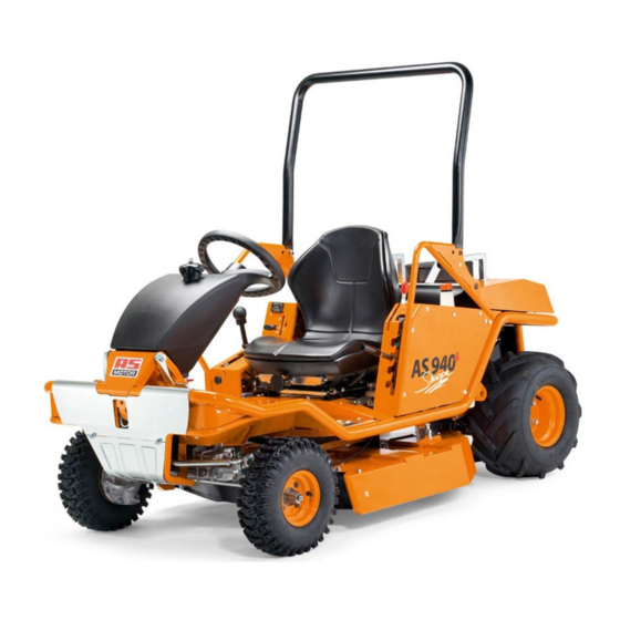
- Page 1 Operator's Manual Ride-on Allmäher® AS 940 Sherpa 4WD RC From serial number: 027419010001 Issued: 12.03.2019, V6.0 en-Translation of the Original Operator's Manual...
- Page 2 Notes on the operating manual Notes on the operating manual Intended use Dear customer, The device is intended for cutting and mulching grass or sim- ilar vegetation in agriculture, forestry, and landscape conser- Congratulations on your purchase. You have acquired a reli- vation.
- Page 3 Contents Contents Tanking up..............Notes on the operating manual........Checking and changing the battery of the transmitter.. Contact ................. Adjusting the seating position........Device data..............Adjusting the seat suspension........Putting up the bar............Intended use..............Transport rack.............. Explanation of the symbols........Switching on receiver and transmitter ......
- Page 4 Contents Checking the spark plug..........Maintaining the air filter..........Checking and charging the battery....... Hydrostat transmission..........Assembly..............Scope of delivery............Unpacking..............Mounting............... Storage ................. Storing the device............Longer storage............. Restarting..............Spare parts..............Wear parts..............Tyres................Disposal................ Warranty............... Troubleshooting ............Error codes..............Technical data..............
- Page 5 Explanation of the symbols dummy Inhaltsverzeichnis Warnings Explanation of the symbols In these operating instructions, warning instructions are marked with signal words. The signal words are used to in- dicate the following hazards and potential consequences. Symbols in the instructions Danger In these operating instructions, the following symbols are used to denote special dangers.
- Page 6 Explanation of the symbols Type plate Prior to any repair and maintenance work, pull off the spark plug connector. The type plate on the device provides you with informa- tion on the device type and the technical data. Risk of tipping! In the ride-on mode (MC), when positioned sideways to the slope, the device is stable up to 21°...
- Page 7 Safety instructions Always close the tank cap tightly and do not open it while the Safety instructions engine is running or the device is still hot. Empty the fuel only when outdoors. Use the approved con- Get informed! tainer for this or run the fuel tank empty. Store the fuel away from children and keep it in a suitable For your safety, read these operating instructions carefully.
- Page 8 Safety instructions General danger area Additional danger area in the RC mode Within the danger area of the device, there is a risk of injury. Due to incorrect or unintended steering or driving move- The rotating blade can cause injuries and objects can be ments, dangerous situations can result.
- Page 9 Safety instructions Use caution during operation Prior to mowing Danger of injury during motor start Personal protective measures The motor must not be started: During mowing, always wear safety shoes with – When fuel was spilled. good grip and long trousers. Do not mow with open sandals or while shoeless.
- Page 10 Safety instructions Mowing surfaces with fire hazard Driving on slopes – Carry a sufficient amount of suitable extinguishing media. If the device, while in use, stops in steep terrain or the engine – If the device leans too much to the side, fuel can leak from cuts out, the device can roll away.
- Page 11 Safety instructions When the uphill wheels encounter obstacles such as roots, Caution when using accessories branches, rocks, mounds etc., the device can tilt or slip. – Only use hitches approved by “AS-Motor Germany”. – Only drive when you know about the terrain conditions and –...
- Page 12 Device description Device description 1 Gearbox fan 2 Silencer grid 3 Transport deposit 4 Antenna 5 Receiver 6 Ventilation grid 7 Oil surge tank 8 Bow 9 Emergency stop 10 Status indicator (on both the right side and the left side of the device) 11 Power socket 12 Fuse circuit (see Technical data)
- Page 13 Control elements on the device Transmitter holder (3) Control elements on the device Insert the transmitter into the transmitter holder Front area 1. Place the transmitter onto the rollers (A) and press down. 2. Insert the transmitter completely into the holder and swing forward.
- Page 14 Control elements on the device Operating hours counter (3) Control lever on seat The operating hours are counted as soon as the engine is running. Display: – When engine is running: engine speed – When engine is off: operating hours Cutting height indicator (4) The top position (0) is the transport posi- tion.
- Page 15 Control elements on the device Selection lever operating modes (6) Rear part Fig. 5: Read the selection lever position on the stickers to the left Status indicators (1) and right of the selection lever. The status indicators on the device flash when the blade is engaged.
- Page 16 Control elements on the device Folding bar Putting down the folding bar Pull the lever (1) out. Put the folding bar (2) down. Swivel the lever forward and engage the lever. Putting up the folding bar Pull the lever (1) out. Swivel the lever down and engage the lever.
- Page 17 Control elements on the device...
- Page 18 Control elements on the transmitter Control elements on the transmitter The transmitter is supplied with 2 keys (A) for the start-stop switch (B). – Key with cap – Key Keep the spare key in a safe place.
- Page 19 Control elements on the transmitter Pos. Symbol Function Type Active in operating mode Transmitter: Start-stop switch (B) RC+MC with key (A) Switching on, switching off, locking Drive forward Joystick Drive backward: Steering to the left Joystick Steering to the right Horn/acknowledge Button RC+MC...
- Page 20 Acoustic signals Carrying the transmitter Warning battery capacity: Quick flashing of an “L”. As soon as the display appears, the trans- mitter can be operated for another approx. 30 minutes. Error code: When the control detects an error, the error code is displayed. For meaning of this code, see chapter Error codes.
- Page 21 Operating modes Operating modes Driving on steep terrain The device can either be operated via remote control Warning (Remote Control = RC mode) or while riding on the device (Manual Control = MC mode). Driving on the slope is dangerous. There is a tilting and slipping hazard.
- Page 22 Oil pressure switch Oil pressure switch Differential lock The oil pressure switch signals via the oil control lamp on the The differential lock connects the two rear wheels rigidly to transmitter when engine damage due to low oil pressure is each other.
- Page 23 Prior to starting Checking the battery Prior to starting Checking the oil level Notice Incorrect oil level can damage the engine. ► Prior to each use, check the engine oil level and the oil level in the hydrostat (see Maintenance). Observe the information in the operator’s manual of the en- gine manufacturer.
- Page 24 Switching on receiver and transmitter Loading limits Adjusting the seat suspension Maximum load: 5 kg The seat suspension should be adjusted to the driver’s Maximum height: 18 cm weight and the terrain features. You will sit most comfortably when the spring travel is fully made use of. Maximum width: 45 cm Maximum length:...
- Page 25 Working in the MC mode Selecting radio frequency Working in the MC mode When you switch on the transmitter, the receiver automatic- ally searches a suitable frequency. Requirements – The selection lever operating mode is set to MC mode. If several remote controlled devices are operated at the same time or when another transmitter is located close by, faults in –...
- Page 26 Working in the MC mode Steering in the MC mode Reversing Always reverse slowly. Be especially cautious when the In the MC mode, steer with the steering wheel. blade is engaged. The joystick for the steering, trimming and steering reversing 1.
- Page 27 Working in the MC mode When crossing over paths, disengage the blade. Engaging the blade in the MC mode 1. Set the blade clutch switch (8) to “0”. Warning ð The blade is disengaged. ð The status indicators do not flash any longer. Risk of injury due to rotating blade.
- Page 28 Working in the MC mode Switching off and parking in the MC mode Switching from the MC mode to the RC mode Warning Warning Risk of injury due to device that is no longer controllable. Risk of injury due to rotating blade. If you switch off the main switch on the device first, the re- ceiver is no longer active.
- Page 29 Practising the RC mode Procedure after an Emergency stop Practising the RC mode Warning Risk of injury due to rotating blade. ► Make sure that nobody is in the danger area. ► Always disengage the blade before you approach the device.
- Page 30 Working in the RC mode Steering in the RC mode Working in the RC mode Warning Requirements Risk of injury due to steering reversing. – The selection lever operating mode is set to RC mode. If you do not know in which position the toggle switch "Re- –...
- Page 31 Working in the RC mode Driving in the RC mode Limiting the speed Fast maximum speed Warning Risk of injury when driving forwards and in reverse. Slow maximum speed ► Make sure that no people are in front of or behind your device and that your path is clear of obstacles.
- Page 32 Working in the RC mode Engaging blade: Engaging the blade in the RC mode 1. For mowing, set the accelerator lever to the maximum speed. Warning 2. Set the highest cutting height. Risk of injury due to rotating blade. 3. Set the blade clutch switch (8) to “I”. ►...
- Page 33 Working in the RC mode 3. Press the start-stop switch (1) on the transmitter. Actuating the differential lock in the RC mode ð The engine is switched off. ð The drive goes to neutral position, the parking brake is active. ð...
- Page 34 Transport Emergency stop in the RC mode Transport Transport the device on a freight vehicle or a trailer which is Causes of the Emergency stop designed for a carrying capacity of at least as great as the – There is a driver in the driver’s seat. empty weight of the device.
- Page 35 Transport Fig. 26: Put the device in front of the ramps and make sure that the ramps – are as wide as the wheel gauge of the device. – are tightly secured to the platform. – are not steeper than 15°. Carefully drive the device via the ramps onto the plat- Fig. 28: form.
- Page 36 Emergency driving programme Moving the device without drive Emergency driving programme Caution Warning Hot silencer grid. Risk of injuries in the emergency driving programme due to ► Do not touch the silencer grid (3), when you push the overridden safety functions. The device can tilt or drive off device.
- Page 37 Maintenance The engine does not start Maintenance and cleaning position 1. Press the button “Horn/Acknowledge” (4) and “Engine start” (5) simultaneously. Warning ð The engine starts automatically, it is possible that the Risk of injury due to the heavy weight of the device. The blade is turning.
- Page 38 Maintenance Maintenance overview Improper maintenance can make the device unsafe for operation and result in accidents. Regular maintenance keeps you device ready for use. Service the device according to the following maintenance instructions. Contact an authorised service centre if problems during maintenance occur or if you determine deficiencies during one of the following inspections.
- Page 39 Maintenance Flammable material Remove easily flammable debris buildup from the engine ■ ▲ and the device. Steering Check the clearance. ■ ▲ Tyres Check tyres and, if necessary, the tyre pressure. ■ ▲ Emergency stop Check. □ ▲ switch Start-stop switch Check.
- Page 40 Maintenance Cleaning the device Checking the RC functions After each use, you should clean the device thoroughly, es- Checking when the engine is not running pecially the bottom side and the blade. Set the selector lever operating modes on the rear of the Stuck grass or dirt affect the grass discharge and the cutting device to RC mode (remote control mode).
- Page 41 Maintenance Checking when the engine is running Checking the Emergency stop switch 1. Start the engine. 1. Select the operating mode MC. ð The device must be stopped. 2. Sit down on the driver’s seat. 2. Pull the accelerator lever all the way up. 3.
- Page 42 Maintenance Checking the automatic blade switchoff Checking the blade 1. Select the operating mode RC. Warning 2. Switch on the transmitter and the receiver. Wear or damage on the blades and the fastening elements 3. Start the engine. can result in the blades or the fastening elements coming 4.
- Page 43 Maintenance Changing the blade Checking the condition of the cutting blade screws Warning When a screw head is worn, the cutting blades can be- come loose. ► Check all screws used for fastening the cutting blades! Fig. 31: Fig. 32: Cutting blades (5) The screw head (3) wears off during mowing and must be re- placed at the latest when it is down to a thickness of 2 mm.
- Page 44 Maintenance Maintaining the engine Checking the engine oil level Never allow the oil level to be too low otherwise the engine Caution can be damaged. Never fill in too much oil. Otherwise, there is the risk that the oil enters and destroys the air filter. If the speed is set too high, objects can be ejected.
- Page 45 Maintenance Hydrostat transmission Warning Danger of chemical burn Warning Batteries contain acids. Contact with battery acid can res- Risk of injury due to high pressure (up to 410 bar) in the ult in blindness or serious burns. hydraulic system. ► Always keep the battery upright and do not spill any bat- ►...
- Page 46 Assembly Assembly Storage Warning Scope of delivery Danger of poisoning due to poisonous exhaust gases. The device is shipped in a carton on a pallet. The scope of ► Do not operate the engine in closed or insufficiently delivery included: ventilated rooms.
- Page 47 Spare parts Spare parts Disposal The reliable and safe operation of the device also depends The device cuts and shreds the growth in a single operation. on the quality of the spare parts used. Only use original spare Shredded plant material decomposes quickly and can be parts and accessories that were approved by used as fertilizer and, therefore, be left on the ground.
- Page 48 Troubleshooting Troubleshooting If a fault occurs, first it is recommended to switch off the transmitter at the start-stop switch and the device at the main switch. Wait 10 seconds and restart the device. If required, also change the frequency (see Selecting radio frequency [} 25]). If the fault persists, the following table and the table error codes will help to inform you about the faults that occur most fre- quently and how to eliminate them.
- Page 49 Troubleshooting Air filter is dirty. Maintain air filter (see Maintenance). Spark plugs are dirty, damaged, Clean spark plugs and check electrode or incorrect electrode gap. gap (see Maintenance). Replace spark plugs if necessary. Housing of the mower is See Maintenance. jammed.
- Page 50 Troubleshooting Strong vibrations dur- Imbalance of the blade caused Have blade resharpened and balanced ing operation by incorrect sharpening or chips by an authorised service centre. Re- on the blade. place a damaged blade immediately. Blade drive shaft is bent due to Authorised service centre.
- Page 51 Troubleshooting Differential lock MC mode. Actuation only possible by hand via the cannot be activated foot pedal. RC mode: Eliminate the Emergency stop situation. An Emergency stop situation occurred Cutting height cannot MC mode: Put driver in seat to activate seat contact be adjusted Safety switches are not actu- switches.
- Page 52 Troubleshooting Error codes When the control detects an error, the error code is displayed. The following table lists the most frequent error codes. Contact an authorised service centre when an error code is displayed that you cannot find in this table. Display Designation Reasons...
- Page 53 Troubleshooting Display Designation Reasons Remedy Microswitch transport posi- Fuse no. 5 (10 A) has blown. Eliminate cause for triggering the fuse and tion does not switch replace fuse. Fuses nos. 1-3 (10 A) have blown. Eliminate cause for triggering the fuse and replace fuse.
- Page 54 Troubleshooting Display Designation Reasons Remedy Interruption of radio trans- Battery of the transmitter is empty. Replace battery. mission Battery of the device is empty. Charge the battery (see Checking the bat- tery) or have authorised service centre do so. Radio range exceeded. Reduce distance between transmitter and re- ceiver.
- Page 55 Technical data Technical data Type AS 940 Sherpa 4WD RC Range of application (temperature) 0 - 30 °C For temperatures below 5 °C, observe the engine manufacturer's informa- tion regarding the engine oil. Engine, type Two cylinder four stroke OHV engine Manufacturer Briggs &...
- Page 56 Technical data Operating mode Sound level according to DIN EN 12733 Measured sound level L 100,3 dB 100,3 dB Sound level L at working place 90,0 dB Sound level L For distance of 15 metres 81,0 dB Measurement uncertainty k 3,0 dB (A) 3,0 dB (A) Vibration emission value according to DIN EN 12733 Hand-arm-vibrations a 1,2 m/s...
- Page 57 Accessories Accessories Steering wheel knob: G06980011 Trailer: G06800003 Trailer hitch: G06900002 Snow remover blade without adaptor: G06837006 Adaptor snow removal blade: G06937014 Adaptor snow blade with weatherproof cabin: G06900005 Weatherproof cabin: G06928001 Mulching kit: G06926034 Spray paint 400 ml, colour orange: G00011050 Flat tyre protection 950 ml: G00041068...
- Page 58 Declaration of conformity AS-Motor Germany GmbH & Co. KG Ellwanger Straße 15 D-74424 Bühlertann www.as-motor.de Declaration of conformity We declare that the grassland mower type AS 940 Sherpa 4WD RC with serial number starting from 027419010001 as brought into circulation by us conforms to all - 2006/42/EC, relevant safety and health requirements of the EC - 2014/30/EC...
- Page 60 AS-Motor Germany GmbH & Co. KG Ellwanger Straße 15 D-74424 Bühlertann www.as-motor.de THE HIGH GRASS MOWER AND 2 STROKE ENGINE MANUFACTURE AS-Motor is your premium manufacturer for lawn and high grass mowers as well as 2 stroke engines. We offer our custom- ers professional technology for steep slopes, rough terrain, and lawn care.
Need help?
Do you have a question about the Allmaher AS 940 Sherpa and is the answer not in the manual?
Questions and answers