probst VZ-I Operating Instructions Manual
Hide thumbs
Also See for VZ-I:
- Operating instructions manual (45 pages) ,
- Operating instructions manual (97 pages) ,
- Operating instructions manual (108 pages)

Related Manuals for probst VZ-I


Summary of Contents for probst VZ-I
- Page 1 VZ-I Betriebsanleitung Operating Instructions Instructions d'emploi Istruzioni d’uso 53100140...
- Page 5 VZ-I Betriebsanleitung 53100140 Original Betriebsanleitung...
- Page 6 Bitte beachten Sie, dass das Produkt ohne vorliegende Betriebsanleitung in Landessprache nicht eingesetzt / in Betrieb gesetzt werden darf. Sollten Sie mit der Lieferung des Produkts keine Betriebsanleitung in Ihrer Landessprache erhalten haben, kontaktieren Sie uns bitte. In Länder der EU / EFTA senden wir Ihnen diese kostenlos nach. Für Länder außerhalb der EU / EFTA erstellen wir Ihnen gerne ein Angebot für eine Betriebsanleitung in Landessprache, falls die Übersetzung nicht durch den Händler/Importeur organisiert werden kann.
-
Page 7: Table Of Contents
Störungsbeseitigung ........................15 Reparaturen ........................... 15 Prüfungspflicht ..........................16 Hinweis zum Typenschild ....................... 17 Hinweis zur Vermietung/Verleihung von PROBST-Geräten ............17 Entsorgung / Recycling von Geräten und Maschinen ..............17 Änderungen gegenüber den Angaben und Abbildungen in der Betriebsanleitung sind vorbehalten. 53100140... -
Page 8: Eg-Konformitätserklärung
DIN EN ISO 13857 Sicherheit von Maschinen - Sicherheitsabstände gegen das Erreichen von Gefährdungsbereichen mit den oberen und unteren Gliedmaßen Dokumentationsbevollmächtigter: Name: Jean Holderied Anschrift: Probst GmbH; Gottlieb-Daimler-Straße 6; 71729 Erdmannhausen, Germany Unterschrift, Angaben zum Unterzeichner: Erdmannhausen, 12.06.2023................(Eric Wilhelm, Geschäftsführer) 53100140... -
Page 9: Sicherheit
Sicherheit Sicherheit Sicherheitshinweise Lebensgefahr! Bezeichnet eine Gefahr. Wenn sie nicht gemieden wird, sind Tod und schwerste Verletzungen die Folge. Gefährliche Situation! Bezeichnet eine gefährliche Situation. Wenn sie nicht gemieden wird, können Verletzungen oder Sachschäden die Folge sein. Verbot! Bezeichnet ein Verbot. Wenn es nicht eingehalten wird, sind Tod und schwerste Verletzungen, oder Sachschäden die Folge. -
Page 10: Sicherheitskennzeichnung
Sicherheit Sicherheitskennzeichnung VERBOTSZEICHEN Symbol Bedeutung Bestell-Nr. Größe 29040210 Ø 30 mm Niemals unter schwebende Last treten. Lebensgefahr! 29040209 Ø 50 mm 29040204 Ø 80 mm 29040213 Ø 30 mm Es dürfen keine konischen Greifgüter gegriffen werden. 29040212 Ø 50 mm 29040211 Ø... -
Page 11: Persönliche Sicherheitsmaßnahmen
Sicherheit Persönliche Sicherheitsmaßnahmen • Jeder Bediener muss die Bedienungsanleitung für das Gerät mit den Sicherheitsvorschriften gelesen und verstanden haben. • Das Gerät und alle übergeordneten Geräte in/an die das Gerät eingebaut ist, dürfen nur von dafür beauftragten und qualifizierten Personen betrieben werden. •... -
Page 12: Sicherheit Im Betrieb
Sicherheit Sicherheit im Betrieb 2.9.1 Allgemeines • Die Arbeit mit dem Gerät darf nur in bodennahem Bereich erfolgen. Das Schwenken des Gerätes über Personen hinweg ist untersagt. • Der Aufenthalt unter schwebender Last ist verboten. Lebensgefahr! • Das manuelle Führen ist nur bei Geräten mit Handgriffen erlaubt. •... -
Page 13: Allgemeines
Allgemeines Allgemeines Bestimmungsgemäßer Einsatz Das Gerät (VZ) ist ausschließlich geeignet zum Greifen und Versetzen von Bordsteinen mit entsprechender Abmessung und kann mit einem Hebezeug, oder als 2-Mann-Gerät bedient werden. ACHTUNG: Das Arbeiten mit diesem Gerät darf nur in bodennahem Bereich erfolgen! (➔ Kapitel „Sicherheit im Betrieb“... - Page 14 Allgemeines • Das Gerät darf nur für den in der Bedienungsanleitung beschriebenen bestimmungsgemäßen Einsatz, unter Einhaltung der gültigen Sicherheitsvorschriften und unter Einhaltung der dementsprechenden gesetzlichen Bestimmungen und den der Konformitätserklärung verwendet werden. • Jeder anderweitige Einsatz gilt als nicht bestimmungsgemäß und ist verboten! •...
-
Page 15: Übersicht Und Aufbau
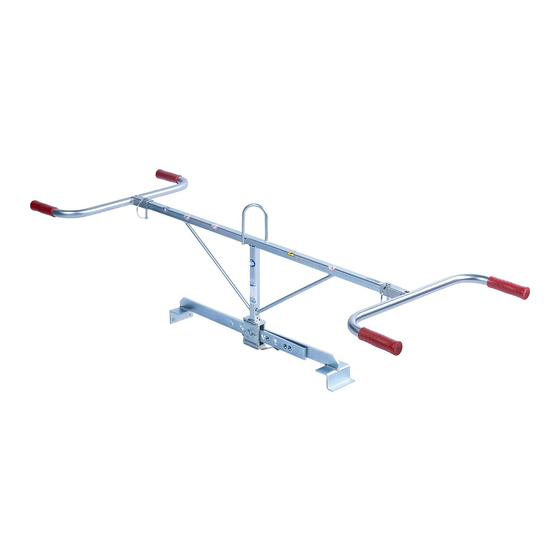
Allgemeines Übersicht und Aufbau Abb.1 Einhängeöse für Kranhaken Greifarme mit Greifbereichsverstellung Handgriff Steckbolzen Greifbacken Technische Daten Die genauen technischen Daten (wie z.B. Tragfähigkeit, Eigengewicht, etc.) sind dem Typenschild zu entnehmen. 53100140 10 / 17... -
Page 16: Installation
Installation Installation Mechanischer Anbau Nur Original-Probst-Zubehör verwenden, im Zweifelsfall Rücksprache mit dem Hersteller halten. Die Tragfähigkeit des Trägergerätes/Hebezeuges darf durch die Last des Gerätes, der optionalen Anbaugeräte (Drehmotor, Einstecktasche, Kranausleger etc.) und die zusätzliche Last der Greifgüter nicht überschritten werden! Greifgeräte müssen immer kardanisch aufgehängt werden, so dass sie in jeder Position frei... -
Page 17: Einstecktaschen (Optional)
Installation 4.1.3 Einstecktaschen (optional) Um eine sichere Verbindung zwischen dem Gabelstapler und der Einstecktasche (3) herzustellen, fährt man mit den Gabelstapler-Zinken (1) in die Einstecktasche (3) hinein. Danach arretiert man diese entweder mittels Arretierungsschrauben (2), welche durch eine vorzusehende Bohrung in die Stapler-Zinken (1) gesteckt wird, oder mittels einer Kette oder eines Seils (4), das durch die Ösen an den Einstecktasche (3) und um den Gabelträger () gelegt werden muss. -
Page 18: Bedienung
Bedienung Bedienung Einstellung des Greifbereichs • Der angegebene Greifbereich des Gerätes lässt sich durch Umstecken des Steckbolzens verstellen. • Klappsplint (1) entfernen und Steckbolzen (2) heraus ziehen. • Greifarme gegeneinander verschieben, bis der gewünschte Greifbereich eingestellt ist. • Steckbolzen (2) wieder in die dafür vorgesehenen Bohrungen einstecken und mit Klappsplint (1) fixieren. -
Page 19: Wartung Und Pflege
Wartung und Pflege Wartung und Pflege Wartung Um eine einwandfreie Funktion, Betriebssicherheit und Lebensdauer des Gerätes zu gewährleisten, sind die in der unteren Tabelle aufgeführten Wartungsarbeiten nach Ablauf der angegebenen Fristen durchzuführen. Es dürfen nur Original-Ersatzteile verwendet werden, ansonsten erlischt die Gewährleistung. Alle Arbeiten dürfen nur bei stillgelegtem Gerät erfolgen! Bei allen Arbeiten muss sichergestellt sein, dass sich das Gerät nicht unabsichtlich schließen kann. -
Page 20: Störungsbeseitigung
Wartung und Pflege Störungsbeseitigung STÖRUNG URSACHE BEHEBUNG Die Klemmkraft ist nicht ausreichend, die Last rutscht (optional) Die Greifbacken sind abgenutzt Greifbacken erneuern (optional) Traglast ist größer als zulässig Traglast reduzieren Greifbereichs-Einstellung Es ist der falsche Greifbereich Greifbereich entsprechend der zu (optional) eingestellt transportierenden Güter einstellen... -
Page 21: Prüfungspflicht
• Die dementsprechenden gesetzlichen Bestimmungen u. die der Konformitätserklärung sind zu beachten! • Die Durchführung der Sachkundigenprüfung kann auch durch den Hersteller Probst GmbH erfolgen. Kontaktieren Sie uns unter: service@probst-handling.de • Wir empfehlen, nach durchgeführter Prüfung und Mängelbeseitigung des Gerätes die Prüfplakette „Sachkundigenprüfung/ Expert inspection“... -
Page 22: Hinweis Zum Typenschild
(z.B. Kran, Kettenzug, Gabelstapler, Bagger...) mit zu berücksichtigen. Beispiel: Hinweis zur Vermietung/Verleihung von PROBST-Geräten Bei jeder Verleihung/Vermietung von PROBST-Geräten muss unbedingt die dazu gehörige Original- Betriebsanleitung mitgeliefert werden (bei Abweichung der Sprache des jeweiligen Benutzerlandes, ist zusätzlich die jeweilige Übersetzung der Original-Betriebsanleitung mit zuliefern)! Entsorgung / Recycling von Geräten und Maschinen... - Page 23 (durch eine autorisierte Fachwerkstatt)! Nach jeder erfolgten Durchführung eines Wartungsintervalls muss unverzüglich dieser Wartungsnachweis (mit Unterschrift u. Stempel) an uns übermittelt werden. per E-Mail an: service@probst-handling.de / per Fax oder Post Betreiber: _ _ _ _ _ _ _ _ _ _ _ _ _ Gerätetyp:...
- Page 25 VZ-I Operating Instructions 53100140 Translation of original operating instructions...
- Page 26 Bitte beachten Sie, dass das Produkt ohne vorliegende Betriebsanleitung in Landessprache nicht eingesetzt / in Betrieb gesetzt werden darf. Sollten Sie mit der Lieferung des Produkts keine Betriebsanleitung in Ihrer Landessprache erhalten haben, kontaktieren Sie uns bitte. In Länder der EU / EFTA senden wir Ihnen diese kostenlos nach. Für Länder außerhalb der EU / EFTA erstellen wir Ihnen gerne ein Angebot für eine Betriebsanleitung in Landessprache, falls die Übersetzung nicht durch den Händler/Importeur organisiert werden kann.
- Page 27 Safety procedures .......................... 15 Hints to the type plate ........................16 Hints to the renting/leasing of PROBST devices ................16 Disposal / recycling of devices and machines .................. 16 We hereby reserve the right to make changes to the information and illustrations in the operating instructions.
-
Page 28: Ec-Declaration Of Conformity / Ukca-Declaration Of Conformity
Address: Probst GmbH; Gottlieb-Daimler-Straße 6; 71729 Erdmannhausen, Germany Authorized person for UK-documentation: Name: Nigel Hughes Address: Probst Ltd ; Unit 2 Fletcher House; Stafford Park 17; Telford Shropshire TF3 3DG, United Kingdom Signature, information to the subscriber: Erdmannhausen, 12.06.2023................(Eric Wilhelm, Managing Director) -
Page 29: Safety
Safety Safety Safety symbols Danger to life! Identifies imminent hazard. If you do not avoid the hazard, death or severe injury will result. Hazardous situation! Identifies a potentially hazardous situation. If you do not avoid the situation, injury or damage to property can result. -
Page 30: Safety Marking
Safety Safety Marking PROHIBITION SIGN Symbol Meaning Order-No. Size 29040210 Ø 30 mm It is not allowed to stand under hanging loads. Danger to life! 29040209 Ø 50 mm 29040204 Ø 80 mm 29040213 Ø 30 mm The transportation of non-rectangular goods is not allowed! 29040212 Ø... -
Page 31: Personal Safety Requirements
Safety Personal safety requirements Each operator must have read and understood the operating instructions (and all safety instructions). Only qualified, authorized personal is allowed to operate the device and all devices which are connected (lifting device/carrier). The manual guiding is only allowed for devices with handles. Otherwise there is a risk of injury to the hands! Protective equipment •... -
Page 32: Safety Procedures
Safety Safety procedures 2.9.1 General • The use of the device is only permitted in proximity to the ground. Do not swing it over people heads. • The stay under lifted load is forbidden. Danger to Life! • The manual guiding of the device is only allowed at the handles. •... -
Page 33: General
General General Authorized use The device (VZ) is specially designed for gripping and transportation of kerb stones with the corresponding dimensions and is usable with a lifting device or as a TWO-MEN-DEVICE. ATTENTION: The use of this device is only permitted in proximity to the ground (→ chapter “Safety at work”... -
Page 34: Survey And Construction
General • The device is only designed for the use specified in this documentation. • Every other use is not authorized and is forbidden! • All relevant safety regulations, corresponding legal regulations, especially regulations of the declaration of conformity, and additional local health and safety regulations must be observed. Prior to every operation the user must ensure that: •... -
Page 35: Installation
Installation Installation Mechanical connection Use only original accessories, in case of doubt consult the manufacturer. Take care that the carrying capacity / working load limit (WLL) of the lifting device/carrier is not exceeded, through the load of the device, the optional attaching devices (turning device, fork sleeves, crane boom etc.) and the additional load of the gripping goods! Gripping devices always have to be gimballed, so they can swing freely in any position. -
Page 36: Fork Sleeves (Optional)
Installation 4.1.3 Fork sleeves (optional) In order to connect the forklift truck and the fork sleeve (3), the forklift truck forks (1) are inserted into the fork sleeve (3). The forks (1) are locked either by using the locking screws (2), which are inserted through a hole in the forks (1), or by using a chain or rope, which must be placed through the eyelet on the fork sleeve (3) and around the fork carrier (). -
Page 37: Operation
Operation Operation Adjustment of the gripping range • The indicated gripping range of the device is adjustable by changing the socket pins. • Remove split pin (1) and pull socket pins (2) out. • Move gripping arms against each other, until the desired gripping is adjusted. •... -
Page 38: Maintenance And Care
Maintenance and care Maintenance and care Maintenance To ensure the correct function, safety and service life of the device the following points must be executed in the maintenance interval. Used only original spare parts, otherwise the warranty expires. All operations may only be made in closed state of the device! For all operations you have to make sure, that the device will not close unintended. -
Page 39: Trouble Shooting
Maintenance and care Trouble shooting ERROR CAUSE REPAIR The clamping-power is not big enough, the load is slipping out optional • • The grippers are worn Replace the grippers optional • • The maximum load is exceed Reduce the weight of. the load •... -
Page 40: Safety Procedures
• The corresponding legal regulations and the regulations of the declaration of conformity must be observed! • The expert inspection can also be done by the manufacturer Probst GmbH. Contact us at: service@probst-handling.de • We recommend affixing the inspection sticker "„Sachkundigenprüfung / Expert inspection" in a clearly visible place (order no.: 2904.0056+Tüv sticker with year number) after the inspection has... -
Page 41: Hints To The Type Plate
Example: Hints to the renting/leasing of PROBST devices With every renting/leasing of PROBST devices the original operating instructions must be included unconditionally (in deviation of the user´s country's language, the respective translations of the original operating instructions must be delivered additionally)! - Page 42 After each completed performance of a maintenance interval the included form must be fill out, stamped, signed and send back to us immediately. via e-mail to service@probst-handling.de / via fax or post Operator: _ _ _ _ _ _ _ _ _ _ _ _ _...
- Page 45 VZ-I Instructions d'emploi 53100140 Traduction des instructions d'emploi originales...
- Page 46 Devoir de contrôle .......................... 16 Informations concernant la plaque signalétique ................17 Remarque concernant la location/le prêt des engins PROBST ............. 17 Elimination / recyclage des appareils et des machines ..............17 Nous nous réservons le droit de modifier les informations et les illustrations du mode d'emploi.
-
Page 47: Ce-Déclaration De Conformité
Sécurité des machines ― Distances de sécurité empêchant les membres supérieurs et inférieurs d'atteindre les zones dangereuses. Personne autorise pour EC-documentation: Nom: Jean Holderied Adresse: Probst GmbH; Gottlieb-Daimler-Straße 6; 71729 Erdmannhausen, Germany Signature, informations ou signataire: Erdmannhausen, 12.06.2023................(Eric Wilhelm, Directeur général) -
Page 48: Sécurité
Sécurité Sécurité Instructions de sécurité Danger mortel ! Indique un danger. Si elle n'est pas évitée, elle peut entraîner la mort et des blessures graves. Situation dangereuse ! Indique une situation dangereuse. Le fait de ne pas l'éviter peut entraîner des blessures ou des dommages matériels. -
Page 49: Signalisation De Sécurité
Sécurité Signalisation de sécurité PANNEAUX D’INTERDICTION Symbole Signification Réf. Taille 29040210 Ø30 mm Ne jamais se placer sous une charge suspendue. Danger de mort 29040209 Ø50 mm 29040204 Ø80 mm 29040213 Ø30 mm Interdiction de saisir des produits coniques. 29040212 Ø50 mm 29040211 Ø80 mm... -
Page 50: Mesures De Sécurité Personnelle
Sécurité Mesures de sécurité personnelle • Chaque opérateur doit avoir lu et assimilé la notice d’instructions de l’appareil, ainsi que les règles de sécurité. • L'appareil et tous les appareils sur et dans lesquels l'appareil est monté ne peuvent être utilisés que par des personnes dûment mandatées, qualifiées et habilitées. -
Page 51: Sécurité En Cours De Fonctionnement
Sécurité Sécurité en cours de fonctionnement 2.9.1 Généralités • Les travaux avec l'appareil ne doivent être effectués que dans une zone proche du sol. Il est interdit de balancer l'appareil sur des personnes. • Il est interdit de rester sous une charge suspendue. Danger pour la vie ! •... -
Page 52: Généralités
Généralités Généralités Utilisation conforme L'appareil (VZ) convient exclusivement à la préhension et à la pose de bordures de dimensions correspondantes et peut être utilisé avec un engin de levage ou comme appareil à deux personnes. ATTENTION: Ne travailler avec l’engin qu’à proximité du sol (→ chapitre « Sécurité en cours de fonctionnement «... - Page 53 Généralités • L’appareil ne peut être utilisé que pour l’usage prévu dans la notice d’instructions, en respectant les règles de sécurité en vigueur, ainsi que les dispositions correspondantes de la déclaration de conformité. • Tout autre usage est considéré comme non conforme à l’usage prévu et est interdit ! •...
-
Page 54: Vue D´ensemble Et Structure
Généralités Vue d´ensemble et structure Ill.1 Œillet d'accrochage Bras préhenseurs Poignée Boulon Mâchoire caoutchouc Caractéristiques techniques Les caractéristiques techniques détaillées (par ex. charge maximale, poids propre, etc.) figurent dans la plaque signalétique. 53100140 10 / 17... -
Page 55: Installation
Installation Montage sur l’appareil porteur N’utiliser que des accessoires Probst d’origine, en cas de doute prendre contact avec le fabricant. La charge admissible de l’appareil porteur /engin de levage ne doit pas être dépassée par la charge de l’appareil et des appareils rapportés (moteur vireur, poches à emboîter, potence etc.) ainsi que par la charge supplémentaire des objets à... -
Page 56: Fourreaux (En Option)
Installation 4.1.3 Fourreaux (en option) Pour établir une liaison sûre entre le chariot élévateur et la poche d'insertion (3), on introduit les dents du chariot élévateur (1) dans la poche d'insertion (3). Ensuite, on les bloque soit au moyen de vis de blocage (2), qui sont introduites dans un trou à prévoir dans les dents du chariot élévateur (1), soit au moyen d'une chaîne ou d'une corde (4), qui doit être passée dans les œillets de la poche de rangement (3) et autour du tablier porte-fourche (). -
Page 57: Maniement
Maniement Maniement Réglage de l’ouverture Régler la zone de préhension comme suit: • Enlever la goupille rabattable (1) de l'axe débrochable (2). • Extraire l'axe débrochable (2). • Pousser le bras de préhension du tube rectangulaire d'avant en arrière jusqu'à ce que le trou correspondant du bras de préhension correspondant dans le bras de préhension concorde avec les trous correspondants du tube rectangulaire. -
Page 58: Maintenance Et Entretien
Maintenance et entretien Maintenance et entretien Maintenance Pour que l´appareil fonctionne parfaitement, pour assurer sa sécurité de fonctionnement et une longue durée de vie, il est impératif d’effectuer les opérations de maintenance spécifiées dans le tableau ci- dessous aux intervalles prescrits. Utiliser exclusivement des pièces de rechange d’origine ;... -
Page 59: Élimination Des Dérangements
Maintenance et entretien Élimination des dérangements DÉRANGEMENT CAUSE DÉPANNAGE La force de serrage est insuffisante, la charge glisse. optional • • Les mâchoires sont usées. Remplacer les mâchoires. optional • • La charge est supérieure à celle Réduire la charge autorisée. -
Page 60: Devoir De Contrôle
Observer les prescriptions correspondantes des associations professionnelles déclaration de conformité. • Le contrôle expert peut également être effectué par le fabricant Probst GmbH. Contactez-nous à : service@probst-handling.de • Lorsqu’un contrôle a été effectué et que les déficiences ont été réparées sur l´appareil, nous conseillons d’apposer la plaquette „CONTRÔLE DE SÉCURITÉ“... -
Page 61: Informations Concernant La Plaque Signalétique
Exemple: Remarque concernant la location/le prêt des engins PROBST Lors de chaque location/prêt d’un engin PROBST, les instructions d’emploi originales correspondantes doivent impérativement être jointes (si la langue n’est pas celle de l’utilisateur, une traduction des instructions d’emploi originales dans la langue adéquate doit être fournie) ! Elimination / recyclage des appareils et des machines Le produit ne doit être mis hors service et préparé... - Page 62 (signée et revêtue de votre cachet). par email à: service@probst-handling.de / par fax ou par courier. Opéateur: _ _ _ _ _ _ _ _ _ _ _ _ _ Modèle:...
- Page 65 VZ-I Istruzioni d’uso 53100140 Traduzione delle istruzioni d'uso originali...
- Page 66 Procedure di sicurezza ........................15 Indicazioni per l’etichetta identificativa ................... 16 Indicazioni per il noleggio/leasing di attrezzature PROBST............16 Smaltimento / riciclaggio di apparecchi e macchinari ..............16 Ci riserviamo il diritto di apportare modifiche alle informazioni e alle illustrazioni delle istruzioni per l'uso.
-
Page 67: Certificato Di Conformita´norme Ce
Sicurezza della macchina ― Distanza di sicurezza al fine di evitare pericolo di passaggio sotto e basso carichi sospesi. Persona autorizzata per CE-documentazione: Nome: Jean Holderied Indirizzo: Probst GmbH; Gottlieb-Daimler-Straße 6; 71729 Erdmannhausen, Germany Firma, dati del sottoscrivente: Erdmannhausen, 13.06.2023................(Eric Wilhelm, Direttore generale) -
Page 68: Sicurezza
Sicurezza Sicurezza Istruzioni di sicurezza Pericolo per la vita! Indica un pericolo. Se non viene evitato, il risultato è la morte e le lesioni gravi. Situazione pericolosa! Indica una situazione di pericolo. Se non viene evitato, possono verificarsi lesioni o danni alle cose. Proibizione! Denota un divieto. -
Page 69: Segni Di Sicurezza
Sicurezza Segni di sicurezza SEGNI DI DIVIETO Simbolo Significato Articolo-N. Misura 29040210 Ø 30 mm Non calpestare mai un carico sospeso. Pericolo per la vita! 29040209 Ø 50 mm 29040204 Ø 80 mm 29040213 Ø30 mm 29040212 Ø50 mm Non è consentito il trasporto di elementi non rettangolari! 29040211 Ø80 mm 29040216... -
Page 70: Misure Di Sicurezza Personali
Sicurezza Misure di sicurezza personali • Tutti gli operatori devono aver letto e compreso le istruzioni d’uso. • Solo apersonale qualificato ed autorizzato è concesso l’utilizzo del dispositivo e delle component collegate (dispositivo di sollevamento). • La guida manual è consentita solo su dispositive con maniglie. Altrimenti c'è... -
Page 71: Sicurezza Durante L'esercizio
Sicurezza Sicurezza durante l'esercizio 2.9.1 Informazioni generali • I lavori con l'apparecchio possono essere eseguiti solo in prossimità del suolo. È vietato far oscillare l'unità sulle persone. • È vietato sostare sotto un carico sospeso. Pericolo per la vita! • La guida manuale è... -
Page 72: Aspetti Generali
Aspetti generali Aspetti generali Uso autorizzato Il dispositivo (VZ I) è realizzato appositamente per la presa e il trasporto di cordoli con le corrispondenti dimensioni ed è utilizzabile come dispositivo di sollevamento per il sollevamento con 2 persone. Non superare la capacità di portata/peso limite di lavoro e il raggio d’apertura del dispositivo (vedi „dati tecnici“). -
Page 73: Panoramica E Struttura
Aspetti generali • L'apparecchio deve essere utilizzato in modo regolare ed esclusivamente per le finalità descritte nelle istruzioni d'uso rispettando le norme sulla sicurezza vigenti e le disposizioni previste dalle norme CE relativamente al certificato di conformità. • È vietato ogni utilizzo diverso da quello previsto dalle norme! •... -
Page 74: Montaggio
Montaggio Montaggio Connessione meccanica Utilizare solamente accessori originali, in caso di dubbio contattar eil produttore. La capacità di carico dell'apparecchio di trasporto/mezzo di sollevamento non deve essere superata dal carico dell'apparecchio, dagli accessori opzionali (motore rotante, tasca d'inserimento, braccio della gru, ecc.) e dal carico supplementare della merce di presa! I dispositivi di presa devono sempre essere fissati in modo da poter oscillare liberamente in qualsiasi posizione. -
Page 75: Tasca Portaforca (Optional)
Montaggio 4.1.3 Tasca portaforca (optional) Per stabilire un collegamento sicuro tra il carrello elevatore e la tasca di inserimento (3), i denti del carrello elevatore (1) vengono inseriti nella tasca di inserimento (3). Il bloccaggio avviene tramite viti di bloccaggio (2), inserite attraverso un foro nei denti del carrello elevatore (1), oppure tramite una catena o una corda (4), che deve essere fatta passare attraverso gli occhielli della tasca di inserimento (3) e attorno al carrello portaforche (). -
Page 76: Funzionamento
Funzionamento Funzionamento Regolazione dell’ampiezza di presa (opzionale) • Il raggio d’apertura del dispositivo può essere regolato cambiano il posizionamento del perno. • Rimuovere il perno (1) estraendo la spinetta a molla (2). • Muovere i bracci fino al raggiungimento della misura desiderata.. •... -
Page 77: Cura E Manutenzione
Cura e manutenzione Cura e manutenzione Manutenzione Affinché l'apparecchio funzioni perfettamente e per garantire la sua sicurezza ed una lunga durata, è necessario effettuare le operazioni di manutenzione precisate nella tabella qui di seguito agli intervalli prescritti. Utilizzare solo parti di ricambio originali, altrimenti decade la garanzia. Per tutti i servizi di manutenzione l’apparecchio deve essere completamente spento!!! Per tutte le operazioni bisogna assicurarsi che l’apparecchio non si chiuda inavvertitamente. -
Page 78: Risoluzione Dei Problemi
Cura e manutenzione Risoluzione dei problemi GUASTO CAUSA RIMEDIO La forza di presa è insufficiente ed il carico scivola. • • Le ganasce della pinza presentano Sostituire le ganasce tracce di usura • • Il carico è superiore al peso Ridurre il peso del carico massimo consentito trasportato... -
Page 79: Procedure Di Sicurezza
• Rispettare le disposizioni previste in materia dalle norme CE indicate nel certificato di conformità!! • L'ispezione peritale può essere eseguita anche dal produttore Probst GmbH. Contattateci all'indirizzo: service@probst-handling.de • Dopo l'esecuzione del controllo e l'eliminazione delle anomalie riscontrate sull'apparecchio raccomandiamo di applicare in un punto ben visibile la targhetta “Sachkundigenprüfung / Expert... -
Page 80: Indicazioni Per L'etichetta Identificativa
Esempio: Indicazioni per il noleggio/leasing di attrezzature PROBST Ad ogni noleggio/leasing delle attrezzature PROBST è obbligatorio includere le istruzioni d’uso originali (a seconda della lingua del paese dell’utilizzatore, verrà fornita in aggiunta la traduzione delle istruzioni d’uso originali)! Smaltimento / riciclaggio di apparecchi e macchinari Il prodotto può... - Page 81 (presso un officina specializzata). Dopo ogni intervento di manutenzione il seguente modulo deve essere compilato, timbrato e firmato e spedito a noi immediatamente. via e-mail a: service@probst-handling.de / via fax o post Operatore: _ _ _ _ _ _ _ _ _ _ _ _ _...
- Page 82 43100016 Blatt 3 43100016 Blatt 3 43101435 Blatt 2 43100016 © all rights reserved conform to ISO 16016 Datum Name Benennung Versetzzange VZ I Erst. 21.10.2004 Klaus.Scholl Gepr. 10.1.2017 I.Krasnikov Artikelnummer/Zeichnungsnummer Blatt E53100140 Zust. Urspr. H020-10001 Ers. f. Ers. d.
- Page 83 20540040 20540040 43100547 43100035 20540001 30320001 41000067 33501204 20040030 43100034 © all rights reserved conform to ISO 16016 Datum Name Benennung Versetzzange VZ I Erst. 21.10.2004 Klaus.Scholl Gepr. 10.1.2017 I.Krasnikov Artikelnummer/Zeichnungsnummer Blatt E53100140 Zust. Urspr. H020-10001 Ers. f. Ers. d.
- Page 84 43101387 21600016 21600016 © all rights reserved conform to ISO 16016 Datum Name Benennung Versetzzange VZ I Erst. 21.10.2004 Klaus.Scholl Gepr. 10.1.2017 I.Krasnikov Artikelnummer/Zeichnungsnummer Blatt E53100140 Zust. Urspr. H020-10001 Ers. f. Ers. d.
- Page 85 A53100140 VZ-I 29040227 29040665 29040221 29040017 29040213 29040213 29040056 29040210 Erstellt/Created: Zuletzt geändert/Last changed: Blatt / Sheet: 1 / 1 16.01.2020 / Simon, Swen 06.02.2023 / Simon, Swen Version: Einige der Abbildungen sind möglicherweise optionales Zubehör des Gerätes/Some of pictures may be optional equipment of the device.
Need help?
Do you have a question about the VZ-I and is the answer not in the manual?
Questions and answers