Table of Contents
Advertisement
Quick Links
Advertisement
Table of Contents

Subscribe to Our Youtube Channel
Related Manuals for Crestron C2N-CBD


Summary of Contents for Crestron C2N-CBD
- Page 1 Crestron C2N/C2NI-CB Series Cameo Keypads ™ Operations & Installation Guide...
- Page 2 This document was prepared and written by the Technical Documentation department at: Crestron Electronics, Inc. 15 Volvo Drive Rockleigh, NJ 07647 1-888-CRESTRON All brand names, product names and trademarks are the property of their respective owners. ©2006 Crestron Electronics, Inc.
-
Page 3: Table Of Contents
Network Wiring ...9 Identity Code ...10 Assembly and Installation ...12 Programming Software ...23 Earliest Version Software Requirements for the PC...23 Programming with Crestron SystemBuilder or D3 Pro...24 Programming with SIMPL Windows...25 Uploading and Upgrading...29 Communication Settings...29 Uploading a SIMPL Windows Program...32 Firmware Upgrade ...35... -
Page 5: Cameo Keypads: C2N/C2Ni-Cb Series
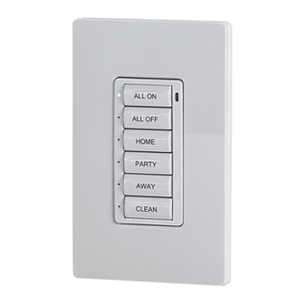
Crestron total solution control system network (Cresnet are available in three versions: C2N-CBF, Flush Mount (no back box required) for domestic and international installation; C2N-CBD, Standard Mount (Decora and C2NI-CBUK, Standard Mount, optional UK-style back box, for UK installation. - Page 6 Additional designer colors are available. (Contact a Crestron customer service representative for details.) Mounting options include a choice of installation as a standalone device using Crestron’s exclusive flush-mounting system; or, for the domestic keypads, Decorator installation in a conventional gang-box using standard Decora mounting (electrical box optional).
-
Page 7: Specifications
.exe files containing the .cuz or .upz file. All can be obtained from the Downloads section of the Crestron website. To avoid program problems, make sure you are using the update file with the correct suffix letter (e.g., S, V, W, X). -
Page 8: Physical Description
(including the FTP site). Physical Description The number of active switches on a keypad can be 1, 2, 3, 4, 5, or 6. Active switches and spacers can be mixed and arranged as needed to suit a particular application. - Page 9 The Crestron Engraver software, Version 2.4 or later, is available from the Crestron website.
- Page 10 ™ Cameo Keypads Crestron C2N/C2NI-CB Series Keypad Overall Dimensions – Flush Mount Configuration 1.73 in (4.38 cm) 1.52 in 2.06 in (3.86 cm) (5.23 cm) 3.20 in (8.13 cm) 6 • Cameo™ Keypads: C2N/C2NI-CB Series Operations & Installation Guide - DOC. 6346A...
- Page 11 ™ Crestron C2N/C2NI-CB Series Cameo Keypads Keypad Overall Dimensions – Decorator Mount Configuration 1.52 in 1.80 in (3.86 cm) (4.56 cm) 4.12 in (10.47 cm) Cameo™ Keypads: C2N/C2NI-CB Series • 7 Operations & Installation Guide - DOC. 6346A...
-
Page 12: Industry Compliance
(1) this device may not cause harmful interference, and (2) this device must accept any interference received, including interference that may cause undesired operation. 8 • Cameo™ Keypads: C2N/C2NI-CB Series Crestron C2N/C2NI-CB Series 1.14 in (2.89 cm) (8.58 cm) 3.38 in... -
Page 13: Setup
CAUTION: Use only Crestron power supplies for Crestron equipment. Failure to do so could cause equipment damage or void the Crestron warranty. CAUTION: Provide sufficient power to the system. Insufficient power can lead to unpredictable results or damage to the equipment. -
Page 14: Identity Code
Refer to “Setting the Net ID in Device Settings” on page 27 for details of the SIMPL Windows procedure. The Net ID of the keypad has been factory set to 25. The Net IDs of multiple keypads in the same system must be unique. Net IDs are changed from a personal computer (PC) via the Crestron Toolbox. - Page 15 Crestron C2N/C2NI-CB Series The Crestron Toolbox provides several methods to easily set or change device Net IDs for any device on the network. The following method permits you to change the Net ID of any device in the network through the “Network Device Tree”...
-
Page 16: Assembly And Installation
The button caps are tapered, and are often installed in a shingle-style pattern (refer to the Usual orientation of the keypad is with the LEDs on the left. It can, however, be inverted with the LEDs on the right, but the original relationship of the button numbers to the LEDs remains, i.e., with the unit... - Page 17 Plastic button support Spring clamp Template Assemble the keypad as described in the following steps. Refer to the accompanying illustrations. 1. Place the button caps and/or spacers in position according to the program plan. Attach the plastic button support to the button caps/spacers, and put the assembled parts in place on the rear housing and switch assembly.
- Page 18 Holes LEDs 5. Attach the spring clamp to the rear of the keypad, as shown in the following figure, by loosening the screws sufficiently to place the clamp over the screws and slide it down into position, and then retighten the screws.
- Page 19 9. Turn Cresnet system power ON. 10. If the keypad needs to be removed from the wall, there is a slot on one edge of the bezel (refer to the figure). Use a small flat blade screwdriver to pry the keypad away from the wall, being careful to avoid damage to the wall surface, and use your fingers to remove the keypad.
- Page 20 Triple row spacer Plastic button support Screws, Steel, Phillips, pan head, 6-32 x 7/8” Assemble the keypad as described in the following steps. Refer to the accompanying illustrations. 1. Arrange the button caps and/or spacers in position according to the program plan.
- Page 21 3. Attach the ground wire to the ground screw of the electrical box. 4. Make sure the keypad is oriented properly, place it in the electrical box, and attach using the supplied 7/8 in. pan head screws.
- Page 22 5. Attach the desired Decora style faceplate (not supplied). 6. Turn the Cresnet system power ON. UK-Style Mounting Installation The keypad for UK-style mounting installation is supplied partially assembled along with several items as listed in the following table. Supplied Parts/Assemblies – UK-Style Mounting...
- Page 23 Triple row spacer Screws, Steel, Phillips, pan head, 6-32 x 7/8” Assemble the keypad as described in the following steps. Refer to the accompanying illustration. 1. Place the button caps and/or spacers in position according to the program plan. Attach the plastic button support to the button caps/spacers, and put the assembled parts in place on the Rear Housing and Switch assembly.
- Page 24 4. Turn the Cresnet system power On. If the keypad needs to be removed from the wall, there are two slots on one edge of the bezel (visible in the figure on page 22). Use a flat blade screwdriver to pry the bezel away from the wall plate, being careful to avoid damage to the bezel.
- Page 25 4. Turn the Cresnet system power On. If the keypad needs to be removed from the wall, there are two slots on one edge of the bezel (visible in the figure on page 22). Use a flat blade screwdriver to pry the bezel away from the wall plate, being careful to avoid damage to the bezel.
- Page 26 ™ Cameo Keypads Crestron C2N/C2NI-CB Series 22 • Cameo™ Keypads: C2N/C2NI-CB Series Operations & Installation Guide - DOC. 6346A...
-
Page 27: Programming Software
Have a question or comment about Crestron software? Answers to frequently asked questions (FAQs) can be viewed in the Online Help section of the Crestron website. To post a question or view questions you have submitted to Crestron’s True Blue Support, log in at http://support.crestron.com. -
Page 28: Programming With Crestron Systembuilder Or D3 Pro
Crestron Toolbox 1.01.11 or later o Engraver 2.5 or later o CUZ 3.137 for 2-Series processors or later • Crestron Engraver version 2.5 (required if using SystemBuilder or to produce custom labeling for the buttons). Programming with Crestron SystemBuilder or... -
Page 29: Programming With Simpl Windows
Both Crestron SystemBuilder and D3 Pro are fully integrated with Crestron's suite of software development tools, including SIMPL Windows, VT Pro-e, and the Crestron Database. Both access these tools behind the scenes, enabling you to easily create robust systems. Programming with SIMPL Windows NOTE: The following assumes that the reader has knowledge of SIMPL Windows. - Page 30 Net ID of 25 as shown in the following illustration. C2Net Device, Slot 9 NOTE: The first Cameo keypad in a system is preset with a net ID of 25 when its symbol is dragged into the upper pane of System Views.
- Page 31 C2N-CB Device Settings Window NOTE: This procedure sets the Net ID for the C2N-CB in the program only. It does not automatically set the Net ID for the keypad itself. NOTE: SIMPL Windows automatically changes Net ID values of a device added to a program if a duplicate device or a device with the same Net ID already exists in the program.
- Page 32 For example, if merging buttons 4, 5, and 6, even though button 6 is now physically at the top of the keypad, button 4 still controls the mode of the merged buttons.
-
Page 33: Uploading And Upgrading
Communication Settings NOTE: For laptops and other PCs without a built-in RS-232 port, Crestron recommends the use of a PCMCIA card over a USB adapter, particularly if using Viewport. The procedure in this section provides details for RS-232 communication between the PC and the control system. - Page 34 Cameo Keypads Typical Connection Diagram when Uploading 1. Open Crestron Toolbox and click Tools | Manage Address Book to display a list of available devices. Select Serial on COM1 as the connection type. Serial on COM1 is an entry in the DefaultAddressBook that is included with Crestron Toolbox.
- Page 35 Crestron C2N/C2NI-CB Series “Address Book” Window – Serial Setup 2. After setting the correct parameters, click OK to return to the Crestron Toolbox main window. 3. Click Tools | Network Device Tree, or click the network device tree icon Serial on COM1 from the drop down list if it is not already selected.
-
Page 36: Uploading A Simpl Windows Program
Uploading a SIMPL Windows Program A control The SIMPL Windows file can be uploaded to the control system source system using SIMPL Windows or via the Crestron file has the extension Toolbox. .smw. A... - Page 37 Crestron C2N/C2NI-CB Series Open Crestron Toolbox. Select Tools | System Info. Crestron Toolbox – Tools | System Info When the “System Info” window appears and you are connected to the control system, the Functions option becomes available from the menu bar.
- Page 38 Keypads “SIMPL Program” Window 6. Click the Browse button to browse for a new compiled (.spz) program file in the “Open” window. “Open” Window 34 • Cameo™ Keypads: C2N/C2NI-CB Series Crestron C2N/C2NI-CB Series Operations & Installation Guide - DOC. 6346A...
-
Page 39: Firmware Upgrade
A firmware To take advantage of all the Cameo keypad features, it is important that upgrade file the unit contains the latest firmware available. Please check the Crestron has the extension .upg. website for the latest version of firmware. Not every product has a... - Page 40 Send to transfer the file. The File Transfer window monitors the transfer of the file and gives you the option of canceling the transfer. 36 • Cameo™ Keypads: C2N/C2NI-CB Series Crestron C2N/C2NI-CB Series Operations & Installation Guide - DOC. 6346A...
- Page 41 Crestron C2N/C2NI-CB Series “File Transfer” Window 8. When the transfer is complete, the “Firmware” window reopens indicating the new firmware version. Click Close after the firmware has been transferred. Operations & Installation Guide - DOC. 6346A ™ Cameo Cameo™ Keypads: C2N/C2NI-CB Series • 37...
-
Page 42: Problem Solving
Crestron website (http://www.crestron.com/) for a listing of Crestron worldwide offices. You can also log onto the online help section of the Crestron website to ask questions about Crestron products. First-time users will need to establish a user account to fully benefit from all available features. -
Page 43: Future Updates
Crestron C2N/C2NI-CB Series Future Updates As Crestron improves functions, adds new features, and extends the capabilities of the Cameo keypad, additional information and programming examples may be made available as manual updates. These updates are solely electronic and serve as intermediary supplements prior to the release of a complete technical documentation revision. -
Page 44: Appendix: Template For Flush Mounting Hole
Photocopies usually alter the size of the image slightly, which would make the hole the wrong size. Be careful when cutting the hole, the spring clamp on the keypad does not have provision for positioning adjustment. Also, ensure that there is a sufficient clearance area behind the mounting surface as shown on the template. -
Page 45: Return And Warranty Policies
CRESTRON shall not be liable to honor the terms of this warranty if the product has been used in any application other than that for which it was intended, or if it has been subjected to misuse, accidental damage, modification, or improper installation procedures. - Page 46 ™ Cameo Keypads Crestron C2N/C2NI-CB Series This page intentionally left blank. 42 • Cameo™ Keypads: C2N/C2NI-CB Series Operations & Installation Guide - DOC. 6346A...
- Page 47 ™ Crestron C2N/C2NI-CB Series Cameo Keypads This page intentionally left blank. Cameo™ Keypads: C2N/C2NI-CB Series • 43 Operations & Installation Guide - DOC. 6346A...
- Page 48 Crestron Electronics, Inc. Operations & Installation Guide - DOC. 6346A 15 Volvo Drive Rockleigh, NJ 07647 (2012599) Tel: 888.CRESTRON 02.06 Fax: 201.767.7576 Specifications subject to www.crestron.com change without notice.
Need help?
Do you have a question about the C2N-CBD and is the answer not in the manual?
Questions and answers