Table of Contents
Advertisement
Quick Links
Advertisement
Table of Contents

Related Manuals for Crestron C2N-DB12


Summary of Contents for Crestron C2N-DB12
- Page 1 Crestron C2N-DB6/8/12 Decorator Wall Panels Operations & Installation Guide...
- Page 2 This document was prepared and written by the Technical Documentation department at: Crestron Electronics, Inc. 15 Volvo Drive Rockleigh, NJ 07647 1-888-CRESTRON All brand names, product names and trademarks are the property of their respective owners. ©2003 Crestron Electronics, Inc.
-
Page 3: Table Of Contents
Industry Compliance...6 Setup...7 Network Wiring ...7 Identity Code ...8 Installation ...12 Programming Software ...13 Programming with Crestron AppBuilder or D3 Pro ...14 Programming with SIMPL Windows...15 Uploading and Upgrading...20 Communication Settings...20 Uploading a SIMPL Windows Program...24 Firmware Upgrade ...25 Serial Number Assignment...27 Problem Solving...29... -
Page 5: Decorator Wall Panels: C2N-Db6/8/12
Introduction Features and Functions The C2N-DB6/8/12-series Decorator Wall Panels are wall-mounted, single-gang user interfaces that can be part of a Crestron control system. The panels are standard Cresnet fingertip control when the control system is properly programmed using Crestron’s SIMPL Windows, Application Builder, or D3 Pro software. - Page 6 SIMPL Windows. In the program, the intensity level for all the button LEDs can be set from 0 to 100%. Refer to “C2N-DB12 Symbol in Programming Manager” on page 17 for details. NOTE: These units do not support audio WAV files.
-
Page 7: Specifications
4. The depth of the wall panel is listed without the Cresnet connector (which would add approximately 0.45 in. plus clearance for the wiring). NOTE: Crestron software and any files on the website are for Authorized Crestron dealers and Crestron Authorized Independent Programmers (CAIP) only. -
Page 8: Physical Description
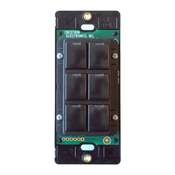
Wall Panel Physical Views 6-button Model Refer to the illustration on page 19 for button arrangement details. 4 • Decorator Wall Panels: C2N-DB6/8/12 Crestron C2N-DB6/8/12 8-button Model 12-button Model Operations & Installation Guide - DOC. 6154... - Page 9 Crestron C2N-DB6/8/12 Button Unit Detail View Side View with buttons installed 1.53 in (3.89 cm) 1.07 in (2.72 cm) (10.57 cm) Installation View Button unit Removable buttons (See CAUTION on page 6.) Divider 2-28 x 3/16 in. pan head Operations & Installation Guide - DOC. 6154...
-
Page 10: Button Replacement
(1) this device may not cause harmful interference, and (2) this device must accept any interference received, including interference that may cause undesired operation. 6 • Decorator Wall Panels: C2N-DB6/8/12 Crestron C2N-DB6/8/12 Operations & Installation Guide - DOC. 6154... -
Page 11: Setup
Setup Network Wiring CAUTION: Use only Crestron power supplies for Crestron equipment. Failure to do so could cause equipment damage or void the Crestron warranty. NOTE: When installing network wiring, refer to the latest revision of the wiring diagram(s) appropriate for your specific system configuration, available from the Downloads | Product Manuals | Wiring Diagrams section of the Crestron website (www.crestron.com). -
Page 12: Identity Code
NET IDs are changed from a Viewport. personal computer (PC) via the Crestron Viewport. NOTE: For detailed information on establishing communication between the PC and control system, refer to “Communication Settings” on page 20. - Page 13 The software checks the baud rate and then opens the "Set Network ID" window. In the "Set Network ID" window, select the C2N-DB12 from the Current Network Devices text window. Select the new NET ID for the wall panel from the Choose the new network ID for the selected device (Hex): text box.
- Page 14 (For a brief description of the D3 Pro program, refer to “Programming with Crestron AppBuilder or D3 Pro” on page 14.) Set Net ID by TSID These procedures are for TSID-enabled network devices during the initial configuration of a Cresnet system or when such devices are being added/replaced.
- Page 15 TSID but not the serial number, and your site installation list is based on device serial numbers. In this (or the reverse) situation, do the following: Open the Crestron Viewport. Operations & Installation Guide - DOC. 6154 Decorator Wall Panels...
-
Page 16: Installation
NOTE: Verify that you have sufficient Cresnet power to support your net devices. Turn Cresnet system power OFF. 12 • Decorator Wall Panels: C2N-DB6/8/12 TSID Conversion Tool. The “Serial Number Operations & Installation Guide - DOC. 6154 Crestron C2N-DB6/8/12 TSID... -
Page 17: Programming Software
Once software Crestron AppBuilder creates the project, the system interfaces and related program logic can be customized. It can easily be modified with Crestron suggestions and/or development tools (i.e., SIMPL Windows and Crestron VisionTools complaints to Pro-e (VT Pro-e) software packages). -
Page 18: Programming With Crestron Appbuilder Or D3 Pro
This custom template can then be used by Crestron AppBuilder to create the final project files to be loaded into the panels. Alternatively, VT Pro-e can be used to tweak projects created with the Crestron AppBuilder or develop original touchpanel screen designs. -
Page 19: Programming With Simpl Windows
It provides a well-designed graphical environment with a number of workspaces (i.e., windows) in which a programmer can select, configure, program, test, and monitor a Crestron control system. SIMPL Windows offers drag and drop functionality in a familiar ... -
Page 20: C2Net-Device Slot In Configuration Manager
NET ID of 71 as shown in the illustration on the next page. NOTE: The first C2N-DB12 in a system is preset with a NET ID of 71 when its symbol is dragged into the upper pane of System Views. - Page 21 Crestron C2N-DB6/8/12 Setting the Net ID in Device Settings Double-click the C2N-DB12 icon in the upper pane to open the “Device Settings” window. This window displays C2N-DB12 device information. The NET ID can be changed in this window using the NET ID tab, as shown in the following figure.
- Page 22 Decorator Wall Panels C2N-DB12 symbol in SIMPL Windows Programming Manager NOTE: In the symbol, the number of press and fbck (feedback)—outputs and inputs, respectively—correspond to the number of buttons in a given wall panel. For example, a C2N-DB8 has only press1-8 and fbck1-8 in its symbol in addition to the LED brightness control (IndicatorIntensity).
- Page 23 NOTE: All signals listed in the table are DIGITAL unless noted. A digital signal can be high (logic level of 1) or low (logic level of 0), and have rising edge (low to high) transitions, and falling edge (high to low) transitions. C2N-DB12 Symbol Signal Descriptions SIGNAL Input fbck1 thru fbck12...
-
Page 24: Example Program
Decorator Wall Panels Example Program An example program for the wall panel is available from the Crestron FTP site (ftp://ftp.crestron.com/Examples). Search for C2N-DB12.ZIP. Uploading and Upgrading Assuming a PC is properly connected to the entire system, Crestron programming software allows the programmer to upload programs and projects to the system and touchpanel and firmware to the wall panels after their development. - Page 25 Crestron C2N-DB6/8/12 serial adapters. If a USB-to-serial adapter must be used, Crestron has tested the following devices with good results: Belkin (large model) F5U103 I/O Gear GUC232A Keyspan USA-19QW Other models, even from the same manufacturer, may not yield the same results.
- Page 26 Decorator Wall Panels Open the Crestron Viewport. Either launch the stand-alone version of Viewport, or start SIMPL Windows and from the menu bar, select Tools | Viewport. Refer to the figure after this step. From the Viewport menu, select Setup | Communications settings (alternatively, press Alt+D) to open the “Port Settings”...
- Page 27 Crestron C2N-DB6/8/12 “Port Settings” Window NOTE: The parameters shown in the illustration above are the port settings for a 2-Series control system. Consult the Operations Guide for the control system being used for exact parameter selection. To verify communication, select Diagnostics | Establish Communications (Find Rack).
-
Page 28: Uploading A Simpl Windows Program
Decorator Wall Panels Uploading a SIMPL Windows Program A control The SIMPL Windows file can be uploaded to the control system using system source SIMPL Windows or via the Crestron Viewport. file has the extension .smw. A Upload via SIMPL Windows compiled Start SIMPL Windows. -
Page 29: Firmware Upgrade
Firmware Upgrade A firmware To take advantage of all the C2N-DB12 features, it is important that the upgrade file unit contains the latest firmware available. Please check the Crestron has the extension website (http://www.crestron.com/downloads/software_updates.asp) for... - Page 30 File Transfer | Update Touchpanel/Keypad Firmware Command As shown in the “Select Network ID” window, select the NET ID of the C2N-DB12, and then click OK. The “Open” window appears (refer to the graphics below and on the next page).
-
Page 31: Serial Number Assignment
These procedures are to be used for wall panels that just received a firmware upgrade enabling TSID support where it was not previously available. Open the Crestron Viewport. From the Viewport menu, select Functions | Assign Serial Number. The “Serial Number Assignment” window appears. - Page 32 Click Send to store the serial number and NET ID information into the wall panel’s memory. 28 • Decorator Wall Panels: C2N-DB6/8/12 Crestron C2N-DB6/8/12 Operations & Installation Guide - DOC. 6154...
-
Page 33: Problem Solving
The table below provides corrective action for possible trouble situations. If further assistance is required, please contact a Crestron customer service representative. Wall Panel Troubleshooting TROUBLE Wall panel does not Incorrect power supply. Use a Crestron power supply. function when a button is pressed. Pressing button yields wrong result. -
Page 34: Further Inquiries
Crestron's award winning customer service team in your area. Dial one of the following numbers. • In the US and Canada, call Crestron's corporate headquarters at 1-888-CRESTRON [1-888-273-7876]. • In Europe, call Crestron International at +32-15-50-99-50. -
Page 35: Return And Warranty Policies
CRESTRON shall not be liable to honor the terms of this warranty if the product has been used in any application other than that for which it was intended, or if it has been subjected to misuse, accidental damage, modification, or improper installation procedures. - Page 36 Crestron Electronics, Inc. Operations & Installation Guide - DOC. 6154 15 Volvo Drive Rockleigh, NJ 07647 06.03 Tel: 888.CRESTRON Fax: 201.767.7576 Specifications subject to www.crestron.com change without notice.
Need help?
Do you have a question about the C2N-DB12 and is the answer not in the manual?
Questions and answers