Table of Contents
Advertisement
Quick Links
Advertisement
Table of Contents

Related Manuals for Crestron C2N-DBF12


Summary of Contents for Crestron C2N-DBF12
- Page 1 Crestron C2N-DBF12 & C2N-DBN12 Decorator Keypads Operations & Installation Guide...
- Page 2 This document was prepared and written by the Technical Documentation department at: Crestron Electronics, Inc. 15 Volvo Drive Rockleigh, NJ 07647 1-888-CRESTRON All brand names, product names and trademarks are the property of their respective owners. ©2006 Crestron Electronics, Inc.
-
Page 3: Table Of Contents
Crestron C2N-DBF12 & C2N-DBN12 Contents Decorator Keypads: C2N-DBF12 & C2N-DBN12 Introduction ... 1 Features and Functions ... 1 Specifications ... 1 Physical Description... 3 Industry Compliance ... 6 Setup ... 7 Network Wiring... 7 Identity Code ... 7 Installation ... 7 Hardware Hookup ... -
Page 5: Decorator Keypads: C2N-Dbf12 & C2N-Dbn12
• Seamless Cresnet * For example, a C2N-DBN12B is a numeric keypad in black. NOTE: Keypads can also be mounted in multi-gang electrical boxes. Specifications Specifications for the C2N-DBF12 & C2N-DBN12 are listed in the following table. C2N-DBF12 & C2N-DBN12 Specifications SPECIFICATION... - Page 6 C2N-DBF/N12A C2N-DBF/N12B C2N-DBF/N12W 1. The latest software versions can be obtained from the Crestron website. Refer to the NOTE following these footnotes. 2. Crestron 2-Series Control Systems include the AV2 and PRO2. Consult the latest Crestron Product Catalog for a complete list of 2-Series Control Systems.
-
Page 7: Physical Description
Crestron C2N-DBF12 & C2N-DBN12 Physical Description This section provides information on the connections, controls and indicators available on your C2N-DBF12 and C2N-DBN12. C2N-DBN12 & C2N-DBF12 Physical Views C2N-DBN12 (Black Color) NOTE: Faceplates, as shown in the above illustration, are not supplied with the keypads. - Page 8 Decorator Keypads Crestron C2N-DBF12 & C2N-DBN12 C2N-DBF12 & C2N-DBN12 Overall Dimensions Side View Front View Back View with buttons installed with divider and buttons removed 1.54 in 1.67 in (3.91 cm) 1.79 in (4.25 cm) (4.55 cm) 1.07 in (2.72 cm) 4.16 in...
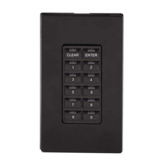
- Page 9 Crestron C2N-DBF12 & C2N-DBN12 Connectors, Controls & Indicators CONNECTORS*, CONTROLS & INDICATORS LED Indicators * Interface connector for NET is provided with the unit. Button Arrangements C2N-DBN12 CLEAR ENTER Operations & Installation Guide – DOC. 6200A (12) Replaceable pre-labeled Buttons buttons, programmable;...
-
Page 10: Industry Compliance
Decorator Keypads The keypads come fully assembled and each has 12 buttons with LED windows (refer to illustration on page 3). The C2N-DBF12 has six source selector buttons, an ON-OFF button, a MUTE button, and device transport control and volume control buttons. A kit with additional source buttons for the C2N-DBF12 is also provided (refer to illustration on page 5). -
Page 11: Setup
The Net ID of the C2NDBF/N12 has been factory set to 71. The Net IDs of multiple C2NDBF/N12 devices in the same system must be unique. Net IDs are changed from a personal computer (PC) via the Crestron Toolbox . When setting the Net ID, consider the following: ™... - Page 12 Make sure that all excess wire is completely inside the electrical box and not between the box and the keypad. 4. Attach the keypad to the electrical box using the supplied two 1-in. pan head screws. 5. Attach faceplate and divider.
-
Page 13: Hardware Hookup
4-position terminal block connector. Apply power after all connections have been made. When making connections to the C2N-DBF/N12, consider the following: • Use Crestron power supplies for Crestron equipment. Operations & Installation Guide – DOC. 6200A Decorator Keypads Single gang electrical box shown;... -
Page 14: Button Replacement
Decorator Keypads Hardware Connections for the C2N-DBF12 & C2N-DBN12 (Back view) Button Replacement Replacing/changing the removable buttons in a keypad is a simple process. Refer to the illustration on previous page and the following procedures. 1. If the keypad is installed in an electrical box, remove the two 1-inch securing screws, carefully pull the keypad from the electrical box, and disconnect the Cresnet cable. - Page 15 Crestron C2N-DBF12 & C2N-DBN12 3. While holding adjacent buttons in place, carefully pull the button(s) to be replaced from the rubber membrane. 4. Carefully press the replacement button(s) in place, make sure LED window(s) orientation is correct, and attach the divider using the four screws removed in step 2.
-
Page 16: Programming Software
Have a question or comment about Crestron software? Answers to frequently asked questions (FAQs) can be viewed in the Online Help section of the Crestron website. To post a question or view questions you have submitted to Crestron’s True Blue Support, log in at http://support.crestron.com. -
Page 17: Programming With Crestron Systembuilder
C2N-DBF/N12, it is recommended to use SystemBuilder for configuring a system. SIMPL Windows is Crestron’s premier software for programming Crestron control systems. It is organized into two separate, but equally important “Managers”. Configuration Configuration Manager is the view where programmers “build” a Manager Crestron control system by selecting hardware from the Device Library. - Page 18 Net ID 71 as shown in the following illustration. C2Net Device, Slot 9 • Additional C2N-DBF12 & C2N-DBN12 devices are assigned different Net ID numbers as they are added. • If necessary, double click a device to open the “Device Settings”...
- Page 19 Programming Manager is the view where programmers “program” a Manager Crestron control system by assigning signals to symbols. The symbol can be viewed by double clicking on the icon or dragging it into Detail View. Each signal in the symbol is described in the SIMPL Windows help file (F1).
-
Page 20: Uploading And Upgrading
Establishing Communication Use Crestron Toolbox for communicating with the C2N-DBF/N12; refer to the Crestron Toolbox help file for details. There is a single method of communication: indirect serial communication. Indirect Serial Communication SERIAL,... - Page 21 ⇒ Select Functions | Firmware… to upgrade the C2N-DBF/N12 firmware. For details on uploading and upgrading, refer to the SIMPL Windows help file or the Crestron Toolbox help file. Operations & Installation Guide – DOC. 6200A Decorator Keypads Decorator Keypads: C2N-DBF/N12 • 17...
-
Page 22: Operation
Decorator Keypads Operation The C2N-DBF12 serves as a source keypad. The C2N-DBN12 can be used to expand the capabilities of the source keypad and is ideal for audio device functions such as selecting a particular CD track number or a certain CD from a CD changer. -
Page 23: Problem Solving
Crestron C2N-DBF12 & C2N-DBN12 Problem Solving Troubleshooting The table below provides corrective action for possible trouble situations. If further assistance is required, please contact a Crestron customer service representative. C2N-DBF12 & C2N-DBN12 Troubleshooting TROUBLE Keypad does not function. (Continued on following page) Operations &... -
Page 24: Check Network Wiring
Calculate CAUTION: Use only Crestron power supplies for Crestron equipment. Power Failure to do so could cause equipment damage or void the Crestron warranty. CAUTION: Provide sufficient power to the system. Insufficient power can lead to unpredictable results or damage to the equipment. Please use the Crestron Power Calculator to help calculate how much power is needed for the system (http://www.crestron.com/calculators). - Page 25 For example, a Cresnet run using 18 AWG Crestron Certified Wire and drawing 20 watts should not have a length of run more than 333 feet. If Cresnet HP is used for the same run, its length could extend to 1250 feet.
-
Page 26: Reference Documents
Crestron website (http://www.crestron.com/) for a listing of Crestron worldwide offices. You can also log onto the online help section of the Crestron website to ask questions about Crestron products. First-time users will need to establish a user account to fully benefit from all available features. -
Page 27: Return And Warranty Policies
Purchasers should inquire of the dealer regarding the nature and extent of the dealer's warranty, if any. CRESTRON shall not be liable to honor the terms of this warranty if the product has been used in any application other than that for which it was intended or if it has been subjected to misuse, accidental damage, modification or improper installation procedures. - Page 28 Crestron Electronics, Inc. Operations & Installation Guide – DOC. 6200A 15 Volvo Drive Rockleigh, NJ 07647 (2009208) Tel: 888.CRESTRON 08.06 Fax: 201.767.7576 Specifications subject to www.crestron.com change without notice.
Need help?
Do you have a question about the C2N-DBF12 and is the answer not in the manual?
Questions and answers