Table of Contents
Advertisement
Quick Links
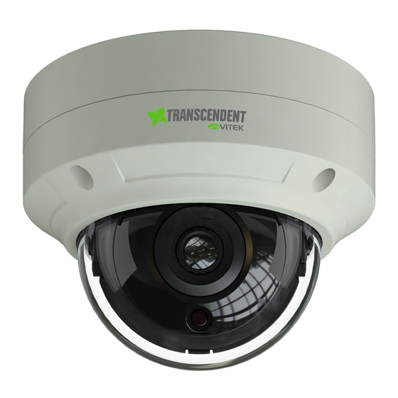
8MP IP Camera Series
Transcendent Series 8 Megapixel [4K]
IP Cameras with Matrix IR
and Gen. III Advanced Analytics
FEATURES
• 1/1.8" (Motorized Models) / (1/2.8" Fixed Models) 8.0 Megapixel
[4K] CMOS Image Sensor
• Up to 30fps (Motorized) / 20fps (Fixed)
@ 8 MegaPixel (3840 x 2160)
• Available with 2.8mm Fixed Lens, or 2.8~12mm Motorized Varifocal Lens
• Matrix IRs with up to 165' IR Range (model dependent)
*up to 230' on VTC-TNB8RMA3
• True Wide Dynamic Range
• True Mechanical Day/Night function by ICR
• XD-DNR (2D & 3D Digital Noise Reduction)
• Gen. III Advanced Analytics: Face Detection, Target Counting, Intrusion, Region
Entrance / Exit, Line Crossing, Scene Change, Video Blur
• 1 Channel Audio In / In + Out / + Built-in Mic* (model dependent)
• 1 Channel Alarm In / In + Out (model dependent)
• Smart H.265 / H.265+ / H.265 / Smart H.264 / H.264+ / H.264 / MJPEG
• Remote Viewing via CMS, Internet Explorer, and iOS & Android Apps
• ONVIF Compliant
• MicroSD Card Slot for Local Recording (256GB)
• IP67 Weather Resistance (+ IK10 Impact on vandal dome models)
• Optional Mounts and Junction Boxes Available (see rear pages)
• 12VDC & PoE (Power over Ethernet) Operation
• All models available in Ivory or Charcoal
• 3 Year Warranty
*Please research local, state and federal laws regarding the implementation of audio surveillance.
Advertisement
Table of Contents

Related Manuals for Vitek Transcendent VTC-TNB8RFA3-2


Summary of Contents for Vitek Transcendent VTC-TNB8RFA3-2
- Page 1 8MP IP Camera Series Transcendent Series 8 Megapixel [4K] IP Cameras with Matrix IR and Gen. III Advanced Analytics FEATURES • 1/1.8” (Motorized Models) / (1/2.8” Fixed Models) 8.0 Megapixel [4K] CMOS Image Sensor • Up to 30fps (Motorized) / 20fps (Fixed) @ 8 MegaPixel (3840 x 2160) •...
- Page 3 Notes on Safety Please read this manual carefully for correct use of the product. Notes Please use the specified power supply to connect the device. ◼ Do not attempt to disassemble the camera. In order to prevent electric shock, do not remove ◼...
- Page 4 Regulatory Information FCC Marking These products have been tested and found to be compliant with the council FCC rules and regulations part 15 subpart B. Operation of this product is subject the following two conditions: (1) this device may not cause harmful interface, and (2) this device must accept any interference received, including interference that may cause undesired operation.
-
Page 5: Table Of Contents
Table of Contents Introduction ................1 Network Connection .............. 2 LAN ..................2 2.1.1 Access through IP-Tool ............... 2 2.1.2 Directly Access through IE ............4 WAN ..................5 Live View ................8 Network Camera Configuration .......... 10 System Configuration ............. 10 4.1.1 Basic Information .............. - Page 6 Network Camera User Manual 4.5.7 Face Detection ................38 Network Configuration ............41 4.6.1 TCP/IP ..................41 4.6.2 Port..................... 42 4.6.3 Server Configuration ..............43 4.6.4 DDNS ..................43 4.6.5 SNMP ..................45 4.6.6 802.1x ..................46 4.6.7 RTSP ..................47 4.6.8 UPNP ..................
-
Page 7: Introduction
Network Camera User Manual 1 Introduction This IP-CAM (short for IP CAMERA) is designed for high performance CCTV solutions. It adopts state of the art video processing chips, integrated with the most advanced technologies (like video encoding and decoding technology) to make the image transmission more stable and smoother. -
Page 8: Network Connection
Network Camera User Manual 2 Network Connection Connect IP-Cam via LAN or WAN. Use IE (Internet Explorer) browser for example. The details are as follows: 2.1 LAN In LAN, there are two ways to access IP-Cam: 1. access through IP-Tool; 2. directly access through IE browser. - Page 9 Network Camera User Manual 3) Modify the IP address. The default IP address of this camera is 192.168.226.201. Click the information of the camera listed in the above table to show the network information on the right side. Modify the IP address and gateway of the camera and make sure its network address is in the same local network segment as the computer’s.
-
Page 10: Directly Access Through Ie
Network Camera User Manual The system will pop up the above-mentioned textbox to ask you to change the default password. It is strongly recommended to change the default password for account security. If “Do not show again” is checked, the textbox will not appear next time. 2.1.2 Directly Access through IE The default network settings are as shown below: IP address: 192.168.226.201... -
Page 11: Wan
Network Camera User Manual Select “Properties” and then select internet protocol according to the actual situation (for example: IPv4). Next, click the “Properties” button to set the network of the PC. 2) Open the IE browser and enter the default address of IP-CAM and confirm. 3) Follow directions to download and install the Active X control. - Page 12 Network Camera User Manual ① Make sure the camera is connected to the local network and then log in the camera via LAN and go to Config→Network→Port menu to set the port number. Port Setup ② Go to Config →Network→TCP/IP menu to modify the IP address. IP Setup ③...
- Page 13 Network Camera User Manual Router Setup ④ Open the IE browser and enter its WAN IP and http port to access. (for example, if the http port is changed to 81, please enter “192.198.1.201:81” in the address bar of web browser to access).
-
Page 14: Live View
Network Camera User Manual Access through static IP ➢ Network connection The setup steps are as follow: ① Go to Config→Network→Port menu to set the port number. ② Go to Config →Network→TCP/IP menu to set the IP address. Check “Use the following IP address”... - Page 15 Network Camera User Manual Icon Description Icon Description Original size Sensor alarm indicator Fit correct scale Motion alarm indicator Auto (fill the window) Color abnormal indicator Full screen Abnormal clarity indicator Start/stop live view Scene change indicator Start/stop two-way audio (only available for the Line crossing indicator model with audio input...
-
Page 16: Network Camera Configuration
Network Camera User Manual 4 Network Camera Configuration In the Webcam client, choose “Config” to go to the configuration interface. Note: Wherever applicable, click the “Save” button to save the settings. 4.1 System Configuration 4.1.1 Basic Information In the “Basic Information” interface, the system information of the device is listed. -
Page 17: Date And Time
Network Camera User Manual Some versions may support device ID and QR code. If P2P is enabled (see Network Configuration-P2P), the network camera can be quickly added to mobile surveillance client, by scanning the QR code or entering device ID. 4.1.2 Date and Time Go to Config→System→Date and Time. -
Page 18: Local Config
Network Camera User Manual 4.1.3 Local Config Go to Config→System→Local Config to set up the storage path of captured pictures and recorded videos on the local PC. There is also an option to enable or disable the bitrate display in the recorded files. Additionally, “Local smart snapshot storage”... - Page 19 Network Camera User Manual ⚫ SD Card Management Click the “Format” button to format the SD card. All data will be cleared by clicking this button. Click the “Eject” button to stop writing data to SD card. Then the SD card can be ejected safely. Snapshot Quota: Set the capacity proportion of captured pictures on the SD card.
-
Page 20: Image Configuration
Network Camera User Manual “Add”: Add the schedule for a special day. Drag the mouse to set the time on the timeline. “Erase”: Delete the schedule. Drag the mouse to erase the time on the timeline. Manual Input: Click it for a specific day to enter specific start and end times. Day schedule Set the alarm time for alarm on a special day, such as a holiday. -
Page 21: Display Configuration
Network Camera User Manual 4.2.1 Display Configuration Go to Image→Display interface as shown below. The image’s brightness, contrast, hue and saturation etc. for common, day and night mode can be set up separately. The image effect can be quickly seen by switching the configuration file. Brightness: Set the brightness level of the camera’s image. - Page 22 Network Camera User Manual instruction.) Auto Iris: If your camera is auto Iris, please enable it. Backlight Compensation (BLC): Off: disables the backlight compensation function. Off is the default mode. ⚫ HWDR: WDR can adjust the camera to provide a better image when there are both very ⚫...
-
Page 23: Video / Audio Configuration
Network Camera User Manual night. Choose “Schedule” in the drop-down box of schedule as shown below. Drag “ ” icons to set the time of day and night. Blue means daytime and blank means nighttime. If the current mode of camera parameters is set to schedule, the image configuration mode will automatically switch between day and night according to the schedule. -
Page 24: Osd Configuration
Network Camera User Manual no matter how much change is seen in the video scene, the compression bitrate will be kept constant. VBR means that the compression bitrate will be adjusted according to scene changes. For example, for scenes that do not have much movement, the bitrate will be kept at a lower value. -
Page 25: Video Mask
Network Camera User Manual Set time stamp, device name, OSD content and picture overlay here. After enabling the corresponding display and entering the content, drag them to change their position. Then click the “Save” button to save the settings. Picture Overlay Settings: Check “OSD Content1”, choose “Picture Overlay”... -
Page 26: Roi Configuration
Network Camera User Manual To set up video mask: 1. Enable video mask. 2. Click the “Draw Area” button and then drag the mouse to draw the video mask area. 3. Click the “Save” button to save the settings. 4. Return to live to verify that the area has been drawn as shown as blocked out in the image. To clear the video mask: Click the “Clear”... -
Page 27: Lens Control
Network Camera User Manual of interest. This area will have a higher bitrate than the rest of the image, resulting in better image quality for the identified area. 1. Check “Enable” and then click the “Draw Area” button. 2. Drag the mouse to set the ROI area. 3. -
Page 28: Ptz Configuration
Network Camera User Manual 4.3 PTZ Configuration This function is only available for the model with RS485 interface. It can be used with a compatible external PTZ enclosure. Go to PTZ→Protocol interface as shown below. 4.4 Alarm Configuration 4.4.1 Motion Detection Go to Alarm→Motion Detection to set motion detection alarm. - Page 29 Network Camera User Manual 1. Check “Enable” check box to activate motion-based alarms. If unchecked, the camera will not send out any signals to trigger motion-based recording to the NVR or CMS, even if there is motion in the video. Alarm Out: If selected, this would trigger an external relay output that is connected to the camera on detecting a motion-based alarm.
-
Page 30: Other Alarms
Network Camera User Manual Move the “Sensitivity” scroll bar to set the sensitivity. Higher sensitivity value means that motion will be triggered more easily. Select “Add” and click “Draw”. Drag the mouse to draw the motion detection area; Select “Erase” and drag the mouse to clear motion detection area. After that, click the “Save”... - Page 31 Network Camera User Manual 2. Click “Enable” and set the alarm holding time. 3. Set alarm trigger options. Trigger alarm out, Email and FTP. The setup steps are the same as motion detection. Please refer to motion detection chapter for details. ⚫...
-
Page 32: Alarm In
Network Camera User Manual 2. Click “Enable” and set the alarm holding time. 3. Trigger alarm out. When the camera is disconnected, the system will trigger the alarm out. 4.4.3 Alarm In This function is only available for some models. To set sensor alarm (alarm in): Go to Config→Alarm→... - Page 33 Network Camera User Manual Alarm Out Mode: Alarm linkage, manual operation, day/night switch linkage and timing are optional. Alarm Linkage: Having selected this mode, select alarm out name, alarm holding time at the “Alarm Holding Time” pull down list box and alarm type. Manual Operation: Having selected this mode, select the alarm type and click “Open”...
-
Page 34: Alarm Server
Network Camera User Manual 4.4.5 Alarm Server Go to Alarm→Alarm Server interface as shown below. Set the server address, port, heartbeat and heartbeat interval. When an alarm occurs, the camera will transfer the alarm event to the alarm server. If an alarm server is not needed, there is no need to configure this section. - Page 35 Network Camera User Manual 1. Enable the applicable detection that’s desired. Scene Change Detection: Alarms will be triggered if the scene has changed. Video Blur Detection: Alarms will be triggered if the video becomes blurry. Enable Video Color Cast Detection: Alarms will be triggered if the video becomes obscured. 2.
-
Page 36: Line Crossing
Network Camera User Manual ※ The requirements of camera and surrounding area 1. Auto-focusing function should not be enabled for exception detection. 2. Try not to enable exception detection when light changes greatly in the scene. 3. Please contact us for more detailed application scenarios. 4.5.2 Line Crossing Line Crossing: Alarms will be triggered if the target crosses the pre-defined alarm line. - Page 37 Network Camera User Manual objects as needed. If no object/target is selected, alarms will not be triggered even if line crossing detection is enabled. 2. Set the alarm holding time. 3. Set alarm trigger options. The setup steps are the same as motion detection. Please refer to motion detection chapter for details.
-
Page 38: Intrusion
Network Camera User Manual 6. Make sure cameras can view objects for at least 2 seconds in the detected area for accurate detection. 7. Adequate light and clear scenery are crucial for line crossing detection. 4.5.3 Intrusion Intrusion: Alarms will be triggered if the target intrudes into the pre-defined areas. This function can be applicable to important supervision places, danger areas and prohibited areas, like military administrative zones, high danger areas, no trespassing areas, etc. -
Page 39: Region Entrance
Network Camera User Manual detection is enabled. 2. Set the alarm holding time. 3. Set alarm trigger options. The setup steps are the same as motion detection. Please refer to motion detection chapter for details. 4. Click the “Save” button to save the settings. 5. - Page 40 Network Camera User Manual 1. Enable region entrance detection and select the snapshot type and the detection target. Save Panoramic Picture: If it is enabled, the detected panoramic pictures will be captured and saved to the SD card when the targets enter the pre-defined areas. Save Target Cutout: If it is enabled, the detected target cutout pictures will be captured and saved to the SD card when the targets enter the pre-defined areas.
-
Page 41: Region Exiting
Network Camera User Manual Set the alarm area number on the right side. Up to 4 alarm areas can be added. Click the “Draw Area” button and then click around the area where you want to set as the alarm area in the image on the left side (the alarm area should be a closed area). Click the “Stop Draw”... - Page 42 Network Camera User Manual 1. Enable region exiting detection and select the snapshot type and the detection target. Save Panoramic Picture: If it is enabled, the detected panoramic pictures will be captured and saved to the SD card when the targets exit from the pre-defined areas. Save Target Cutout: If it is enabled, the detected target cutout pictures will be captured and saved to the SD card when the targets exit from the pre-defined areas.
-
Page 43: Target Counting
Network Camera User Manual as schedule recording setup (See Schedule Recording). * The configuration requirements of camera and surrounding area are the same as intrusion detection 4.5.6 Target Counting This function is to calculate the number of people or vehicles crossing the alarm line through detecting, tracking and counting the shapes of people or vehicles. -
Page 44: Face Detection
Network Camera User Manual Set the alarm line number and direction. Only one alarm line can be added. Direction:A->B and A<-B can be optional. The direction of the arrow is entrance. Click the “Draw Area” button and then drag the mouse to draw a line in the image. Click the “Stop Draw”... - Page 45 Network Camera User Manual 1. Go to Config→Event→Face Detection as shown below. 2. Enable the face detection function. Save Source Information: if checked, the whole picture will be saved to the SD card when detecting a face. Save Face Information: if checked, the captured face picture will be saved to the SD card when detecting a face.
- Page 46 Network Camera User Manual Click “Draw Area” and drag the border lines of the rectangle to modify its size. Move the rectangle to change its position. Click “Stop Draw” to stop drawing the area. Click “Clear” to clear the area. Then set the detectable face size by defining the maximum value and the minimum value (The default size range of a single face image occupies from 3% to 50% of the entire image).
-
Page 47: Network Configuration
Network Camera User Manual ※ Configuration requirements of camera and surrounding area 1. Cameras must be installed in an area with stable and adequate light sources. 2. The installation height ranges from 6 to 12 feet, adjustable according to the focal length of different lenses and object distances. -
Page 48: Port
Network Camera User Manual options as needed. Test: Test the effectiveness of the IP address by clicking this button. Use PPPoE-Click the “PPPoE Config” tab to go to the interface as shown below. Enable PPPoE and then enter the username and password from your ISP. Either method of network connection can be used. -
Page 49: Server Configuration
Network Camera User Manual RTSP Port: The default port is 554. Please change it as necessary. 4.6.3 Server Configuration This function is mainly used for connecting network video management system. 1. Check “Enable”. 2. Check the IP address and port of the transfer media server in the CMS. Then enable the auto report in the CMS when adding a new device. - Page 50 Network Camera User Manual Create domain name. After the domain name is successfully applied for, the domain name will be listed as below.
-
Page 51: Snmp
Network Camera User Manual 3. Enter the username, password, domain you apply for in the DDNS configuration interface. 4. Click the “Save” button to save the settings. 4.6.5 SNMP To get camera status, parameters and alarm information and remotely manage the camera, the SNMP function can be used. -
Page 52: 802.1X
Network Camera User Manual 2. Check the corresponding version checkbox (Enable SNMPv1, Enable SNMPv2, Enable SNMPv3) according to the version of the SNMP software that will be used. 3. Set the values for “Read SNMP Community”, “Write SNMP Community”, “Trap Address”, “Trap Port”... -
Page 53: Rtsp
Network Camera User Manual To use this function, the camera should be connected to a switch supporting 802.1x protocol. The switch can be reckoned as an authentication system to identify the device in a local network. If the camera connected to the network interface of the switch has passed the authentication of the switch, it can be accessed via the local network. -
Page 54: Upnp
Network Camera User Manual “rtsp://IP address: rtsp port/profile3?transportmode=mcast”. Audio: Having entered the main/sub stream in a VLC player, the video and audio will play automatically. If “Allow anonymous login…” is checked, there is no need to enter the username and password to view the video. -
Page 55: Ftp
Network Camera User Manual Sender Address: sender’s e-mail address. Username and password: sender’s user name and password. Server Address: The SMTP IP address or host name. Select the secure connection type at the “Secure Connection” pull-down list according to what’s required. -
Page 56: Https
Network Camera User Manual Server Name: The name of the FTP server. Server Address: The IP address or domain name of the FTP. Upload Path: The directory where files will be uploaded to. Port: The port of the FTP server. Username and Password: The username and password that are used to login to the FTP server. -
Page 57: P2P (Optional)
Network Camera User Manual * If there is a signed certificate, click “Browse” to select it and then click “Install” to install it. * Click “Create a private certificate” to enter the following creation interface. Click the “Create” button to create a private certificate. Enter the country (only two letters available), domain (camera’s IP address/domain), validity date, password, province/state, region and so on. -
Page 58: Security Configuration
Network Camera User Manual 4.6.13 QoS QoS (Quality of Service) function is used to provide different quality of services for different network applications. With low bandwidth, the router or switch will sort the data streams and transfer them according to their priority to solve the network delay and network congestion by using this function. - Page 59 Network Camera User Manual 2. Enter username in “User Name” textbox. 3. Enter the password in the “Password” and “Confirm Password” textbox. Please set the password according to the requirement of the password security level (Go to Config→Security→ Security Management→Password Security interface to set the security level).
-
Page 60: Online User
Network Camera User Manual 4.7.2 Online User Go to Config→Security→Online User to view the user who is viewing the live video. An administrator user can kick out all the other users (including other administrators). 4.7.3 Block and Allow Lists Go to Config→Security→Block and Allow Lists as shown below. The setup steps are as follows: Check the “Enable address filtering”... -
Page 61: Maintenance Configuration
Network Camera User Manual Password Security ⚫ Please set the password level and expiration time as needed. Password Level: Weak, Medium or Strong. Weak level: Numbers, special characters, upper or lower case letters can be used. You can choose one of them or any combination of them when setting the password. Medium Level: 9~15 characters, including at least two of the following categories: numbers, special characters, upper case letters, lower case letters. -
Page 62: Reboot
Network Camera User Manual Import & Export Settings ⚫ Configuration settings of the camera can be exported form a camera into another camera. 1. Click “Browse” to select the save path for import or export information on the PC. 2. Click the “Import Setting” or “Export Setting” button. Default Settings ⚫... - Page 63 Network Camera User Manual 2. Select the main type, sub type, start and end time. 3. Click “Search” to view the operation log. 4. Click “Export” to export the operation log.
-
Page 64: Search
Network Camera User Manual 5 Search 5.1 Image Search Click Search to go to the interface as shown below. Images that are saved on the SD card can be found here. ⚫ Local Image Search Choose “Picture”— “Local”. Set time: Select date and choose the start and end time. Click to search the images. - Page 65 Network Camera User Manual Click to return to the previous interface. ⚫ SD Card Image Search Choose “Picture”— “SD Card”. Set time: Select date and choose the start and end time. Choose the alarm events at the bottom of the interface. Click to search the images.
-
Page 66: Video Search
Network Camera User Manual Icon Description Icon Description Play speed: Play speed of the slide show. 5.2 Video Search 5.2.1 Local Video Search Click Search to go to the interface as shown below. Videos were recorded locally to the PC can be played in this interface. -
Page 67: Sd Card Video Search
Network Camera User Manual Icon Description Icon Description Play button. After pausing the video, click this button Pause button to continue playing. Stop button Speed down Speed up Watermark display Enable / disable audio; drag the slider to adjust the volume after enabling audio. - Page 68 Network Camera User Manual Select the alarm events at the bottom of the interface. Select mix stream (video and audio stream) or video stream as needed. Double click on a file name in the list to start playback. The timetable can be shown in 24H/12H/2H/1H format by clicking the corresponding buttons. Video clip and downloading Search the video files according to the above mentioned steps.
- Page 69 Network Camera User Manual Select the end time by clicking on the timetable. Then click to set the end time. Click to download the video file in the PC. Click “Set up” to set the storage directory of the video files. Click “Open”...
- Page 70 Detailed Specifications VTC-TNB8RFA3-2 / VTC-TNB8RFA3B-2 Image Sensor 1/2.8” 8.0 Megapixel [4K] Progressive Scan CMOS Image Size 8 MegaPixel (3840 x 2160) Resolution 8 MP (3840 x 2160 ) 4 MP (2592 × 1520) / 3 MP (2304 × 1296) / 1080P (1920 ×...
- Page 71 Detailed Specifications VTC-TNB8RMA3 / VTC-TNB8RMA3B Image Sensor 1/1.8” 8.0 Megapixel [4K] Progressive Scan CMOS Image Size 8 MegaPixel (3840 x 2160) Resolution 8 MP (3840 x 2160 ) 4 MP (2592 × 1520) / 3 MP (2304 × 1296) / 1080P (1920 ×...
- Page 72 Detailed Specifications VTC-TNT8RFA3-2 / VTC-TNT8RFA3B-2 Image Sensor 1/2.8” 8.0 Megapixel [4K] Progressive Scan CMOS Image Size 8 MegaPixel (3840 x 2160) Resolution 8 MP (3840 x 2160 ) 4 MP (2592 × 1520) / 3 MP (2304 × 1296) / 1080P (1920 ×...
- Page 73 Detailed Specifications VTC-TNT8RMA3 / VTC-TNT8RMA3B Image Sensor 1/1.8” 8.0 Megapixel [4K] Progressive Scan CMOS Image Size 8 MegaPixel (3840 x 2160) Resolution 8 MP (3840 x 2160 ) 4 MP (2592 × 1520) / 3 MP (2304 × 1296) / 1080P (1920 ×...
- Page 74 Detailed Specifications VTD-TND8RFA3-2 / VTD-TND8RFA3B-2 Image Sensor 1/2.8” 8.0 Megapixel [4K] Progressive Scan CMOS Image Size 8 MegaPixel (3840 x 2160) Resolution 8 MP (3840 x 2160 ) 4 MP (2592 × 1520) / 3 MP (2304 × 1296) / 1080P (1920 ×...
- Page 75 Detailed Specifications VTD-TND8RMA3 / VTD-TND8RMA3B Image Sensor 1/1.8” 8.0 Megapixel [4K] Progressive Scan CMOS Image Size 8 MegaPixel (3840 x 2160) Resolution 8 MP (3840 x 2160 ) 4 MP (2592 × 1520) / 3 MP (2304 × 1296) / 1080P (1920 ×...
- Page 76 OPTIONAL ACCESSORIES FOR TRANSCENDENT IP CAMERAS VT-TJB07 VT-TJB08 VT-TJB01 Optional Junction Box for Optional Junction Box Optional Junction Box Use with Select for Use with Select for Use with Select Transcendent Transcendent Bullet Transcendent Bullet Bullet Cameras and Fixed Lens Turret and Turret Cameras Cameras VT-TJB021...
- Page 77 VT-WAP1250 With high speed transmission of 150MBps and a wireless range of & VT-WAP1150 up to 1.25 miles, Vitek Wireless Access Points eliminate the need for expensive and troublesome long distance cabling in remote areas where CCTV monitoring takes place!
- Page 78 Network Camera User Manual SEPTEMBER 2020 VERSION 1.0 DECEMBER 2020 APRIL 2020 Vitek IVP, Inc. 28492 Constellation Blvd, Valencia, CA 91355 www.vitekcctv.com...
Need help?
Do you have a question about the Transcendent VTC-TNB8RFA3-2 and is the answer not in the manual?
Questions and answers