Sungrow SG30CX User Manual
Pv grid-connected inverter
Hide thumbs
Also See for SG30CX:
- User manual (129 pages) ,
- Quick manual (21 pages) ,
- Quick manual (16 pages)

Subscribe to Our Youtube Channel
Related Manuals for Sungrow SG30CX


Summary of Contents for Sungrow SG30CX
- Page 1 PV Grid-Connected Inverter User Manual SG30CX / SG33CX / SG40CX / SG50CX WWW.SUNGROWPOWER.COM SG30_33_40_50CX-UEN-Ver18-202106...
-
Page 3: All Rights Reserved
No part of this document can be reproduced in any form or by any means without the prior written permission of Sungrow Power Supply Co., Ltd (hereinafter "SUNGROW"). T T r r a a d d e e m m a a r r k k s s and other Sungrow trademarks used in this manual are owned by SUNGROW. -
Page 4: About This Manual
. . s s u u n n g g r r o o w w p p o o w w e e r r . . c c o o m m or on the webpage of the respective component manufacturer. V V a a l l i i d d i i t t y y This manual is valid for the following inverter models: SG30CX • SG33CX • SG40CX •... - Page 5 Indicates a hazard with a medium level of risk that, if not avoided, could result in death or serious injury. Indicates a hazard with a low level of risk that, if not avoided, could result in mi- nor or moderate injury. Indicates a situation that, if not avoided, could result in equipment or property damage.
-
Page 7: Table Of Contents
C C o o n n t t e e n n t t s s All Rights Reserved .....................I About This Manual .....................II 1 Safety ......................1 1.1 PV Panels..................... 1 1.2 Utility Grid ....................1 1.3 Inverter ......................2 2 Product Description .................. - Page 8 4.6 Installing the Inverter .................. 23 5 Electrical Connection ................25 5.1 Safety Instructions..................25 5.2 Terminal Description................... 25 5.3 Electrical Connection Overview ..............26 5.4 Crimp OT/DT terminal................. 28 5.5 Additional Grounding Connection ............... 29 5.5.1 Additional Grounding Requirements..........29 5.5.2 Connection Procedure ..............
- Page 9 7.2 Installing the App..................53 7.3 Function Overview ..................54 7.4 Login......................54 7.4.1 Requirements ................... 54 7.4.2 Login Procedure ................54 7.5 Home page ....................56 7.6 Run Information ..................58 7.7 Records ..................... 60 7.8 More ......................62 7.8.1 System Parameters ................
-
Page 11: Safety
The safety instructions in this manual cannot cover all the precautions that should be followed. Perform operations considering actual onsite conditions. SUNGROW shall not be held liable for any damage caused by violation of the safety instructions in this manual. -
Page 12: Inverter
1 Safety User Manual All electrical connections must be in accordance with local and national standards. Only with the permission of the local utility grid company, the inverter can be connected to the utility grid. 1.3 Inverter Danger to life from electric shocks due to live voltage Do not open the enclosure at any time. - Page 13 User Manual 1 Safety Only qualified personnel can perform the country setting. Unauthorized altera- tion may cause a breach of the type-certificate marking. Risk of inverter damage due to electrostatic discharge (ESD)! By touching the electronic components, you may damage the inverter. For in- verter handling, be sure to: avoid any unnecessary touching;...
-
Page 14: Product Description
I I t t e e m m N N o o t t e e Monocrystalline silicon, polycrystalline silicon and thin-film PV strings without grounding. SG30CX, SG33CX, SG40CX, SG50CX. Inverter Grid connection Includes devices such as AC circuit breaker, SPD, metering cabinet device. -
Page 15: Product Introduction
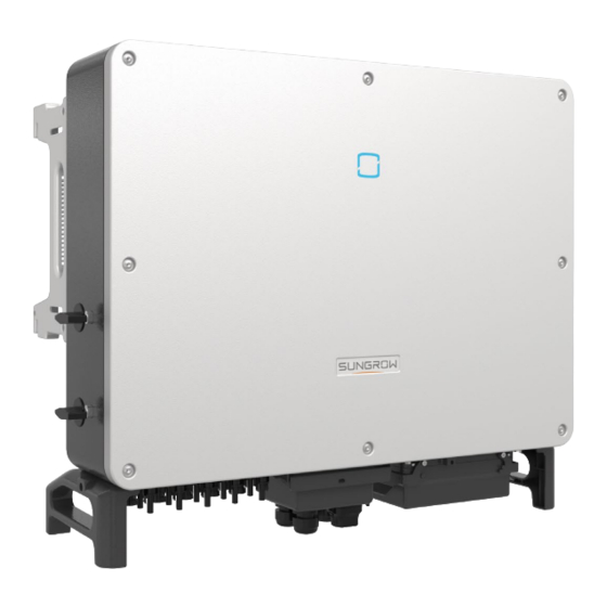
M M o o d d e e l l D D e e s s c c r r i i p p t t i i o o n n The model description is as follows(Take SG30CX as an example) : A A p p p p e e a a r r a a n n c c e e The following figure shows the dimensions of the inverter. - Page 16 2 Product Description User Manual f f i i g g u u r r e e 2 2 - - 2 2 Inverter Appearance D D e e s s c c r r i i p p t t i i o o n n N N o o .
-
Page 17: Symbols On The Product
D D i i m m e e n n s s i i o o n n s s ( ( W W * * H H * * D D ) ) W W e e i i g g h h t t SG30CX 50 kg 702×595×310mm... -
Page 18: Dc Switch
2.5 DC Switch The DC switch is used to disconnect the DC current safely whenever necessary. The SG30CX and SG33CX is equipped with one DC switch to control the connection and disconnection of all DC terminals. The SG40CX and SG50CX are equipped with two DC switches separately controlling a group of DC inputs. -
Page 19: Circuit Diagram
The standard RS485 communication interfaces are used to establish communication connection with monitoring devices and upload monitoring data by using communica- tion cables. The communication accessory port is used to connect communication module manu- factured by SUNGROW, and upload monitoring data by means of wireless communication. - Page 20 After communication connection is established, users can view inverter information or set inverter parameters through the iSolarCloud. It is recommended to use the communication module from SUNGROW. Using a device from other companies may lead to communication failure or other unexpected damage.
- Page 21 User Manual 2 Product Description Before enabling the PID recovery function, make sure the voltage polarity of • the PV modules to ground meets requirement. If there are any questions, contact the PV module manufacturer or read the corresponding user manual. PID recovery function and Q at night cannot be enabled at the same time.
-
Page 22: Unpacking And Storage
Check the inner contents for damage after unpacking. • Contact SUNGROW or the transport company in case of any damage or incomplete- ness, and provide photos to facilitate services. Do not dispose of the original packing case. It is recommended to store the device in the original packing case when the device is decommissioned. -
Page 23: Mechanical Mounting
Mechanical Mounting Respect all local standards and requirements during mechanical installation. 4.1 Safety during Mounting Make sure there is no electrical connection before installation. In order to avoid electric shock or other injury, make sure that holes will not be drilled over any electricity or plumbing installations. -
Page 24: Environment Requirements
4 Mechanical Mounting User Manual 4.2.1 Environment Requirements The installation environment must be free of inflammable or explosive materials. • The location should be not accessible to children. • The ambient temperature and relative humidity must meet the following • requirements. -
Page 25: Clearance Requirements
User Manual 4 Mechanical Mounting In case the installation site is a level surface, mount the inverter to the horizon- tal-mounting bracket to meet the mounting angle requirements, as shown in the figure below. Take the following items into account when designing the bracket scheme: Consider onsite climate conditions and take anti-snow and anti-rain meas- •... - Page 26 4 Mechanical Mounting User Manual * In case the distance is less than 450 mm, move the inverter from the mounting-bracket or wall before maintaining fans. The distance between the bottom of the inverter and the ground surface is de- termined according to the bending radius of the AC cable used and the instal- lation environment.
-
Page 27: Installation Tools
User Manual 4 Mechanical Mounting In case of back-to-back installation, reserve specific clearance between the two inverters. Install the inverter at an appropriate height for ease of viewing LED indicator and operat- ing switch(es). 4.3 Installation Tools Installation tools include but are not limited to the following recommended ones. If nec- essary, use other auxiliary tools on site. -
Page 28: Moving The Inverter
4 Mechanical Mounting User Manual Hammer drill Pliers Marker Level (φ12, φ14) Rubber mallet Wrench Wrist strap Socket wrench set (16mm) (13 mm, 16 mm) Wire cutter Wire stripper Hydraulic plier Heat gun MC4 terminal MC4 terminal Multimeter RJ45 crimping tool crimping pliers wrench ≥... -
Page 29: Manual Transport
User Manual 4 Mechanical Mounting Always be aware of the weight of the inverter. • Lift the inverter using the handles positioned on both sides of the inverter. • Move the inverter by one or two people or by using a proper transport tool. •... - Page 30 4 Mechanical Mounting User Manual step 2 Lead the sling through the two lifting rings and fasten the tie-down strap. step 3 Hoist the inverter, and stop to check for safety when the inverter is 100mm above the ground. Continue hoisting the device to the destination after ensuring the safety. step 4 Remove the lifting rings and reassemble the sealing screws released in Step 1.
-
Page 31: Installing The Mounting-Bracket
User Manual 4 Mechanical Mounting The lifting rings and the sling are not within the delivery scope. - - - - E E n n d d 4.5 Installing the mounting-bracket Inverter is installed on the wall and bracket by means of mounting bracket. The expansion plug set shown below is recommended for the installation. -
Page 32: Wall-Mounted Installation
4 Mechanical Mounting User Manual C C o o m m p p o o n n e e n n t t s s D D e e s s c c r r i i p p t t i i o o n n N N o o . -
Page 33: Installing The Inverter
User Manual 4 Mechanical Mounting step 4 Fix the mounting-bracket with the expansion bolts. C C o o m m p p o o n n e e n n t t s s D D e e s s c c r r i i p p t t i i o o n n N N o o . - Page 34 4 Mechanical Mounting User Manual - - - - E E n n d d...
-
Page 35: Electrical Connection
Electrical Connection 5.1 Safety Instructions Prior to any electrical connections, keep in mind that the inverter has dual power sup- plies. It is mandatory for the qualified personnel to wear personal protective equipments (PPE) during the electrical work. Danger to life due to a high voltage inside the inverter! The PV string will generate lethal high voltage when exposed to sunlight. -
Page 36: Electrical Connection Overview
T T e e r r m m i i n n a a l l M M a a r r k k N N o o t t e e MC4 PV connector SG30CX, SG33CX: 6 pairs of terminals PV terminals + / - SG40CX: 8 pairs of terminals SG50CX: 10 pairs of terminals For RS485 communication wiring. - Page 37 Outdoor single- The same as that of the PE wire in the AC grounding core copper wire cable cable cable L1,L2,L3,N wire (SG30CX, SG33CX): 16 ~ 35 L1,L2,L3,N wire Outdoor multicore (SG40CX): 25 ~ 50 AC cable copper or alumi-...
-
Page 38: Crimp Ot/Dt Terminal
5 Electrical Connection User Manual table 5-2 PE Wire Requirements P P h h a a s s e e W W i i r r e e C C r r o o s s s s P P E E W W i i r r e e C C r r o o s s s s N N o o t t e e S S e e c c t t i i o o n n S S S S e e c c t t i i o o n n... -
Page 39: Additional Grounding Connection
The ground connection of this additional grounding terminal cannot replace • the connection of the PE terminal of the AC cable. Make sure those terminals are both grounded reliably. SUNGROW shall not be held liable for any dam- age caused by the violation. 5.5.1 Additional Grounding Requirements All non-current carrying metal parts and device enclosures in the PV power system should be grounded, for example, mounts of PV modules and the inverter enclosure. -
Page 40: Connection Procedure
R R e e c c o o m m m m e e n n d d e e d d r r a a t t e e d d v v o o l l t t a a g g e e I I n n v v e e r r t t e e r r c c u u r r r r e e n n t t SG30CX 400V... - Page 41 M M u u l l t t i i p p l l e e I I n n v v e e r r t t e e r r s s i i n n P P a a r r a a l l l l e e l l C C o o n n n n e e c c t t i i o o n n If multiple inverters are connected in parallel to the grid, ensure that the total number of parallel inverters does not exceed 30. Otherwise, please contact SUNGROW for techni- cal scheme.
-
Page 42: Requirements For Ot/Dt Terminal
• er. The maximum AC current of all inverters connected in parallel must be taken into account. If more than 30 inverters are connected to the grid, contact SUNGROW. The transformer must be protected against overloading and short circuit. •... - Page 43 User Manual 5 Electrical Connection O O u u t t e e r r d d i i a a m m e e t t e e r r D D ( ( m m m m ) ) S S e e a a l l s s 30~40 40~50...
-
Page 44: Dc Cable Connection
5 Electrical Connection User Manual Ensure that the depth L of the socket used is not less than 18mm. step 7 Secure the junction box, fasten the buckle, and secure it with supplied M4×10 screw. step 8 Gently pull the cable backwards to ensure firm connection, and fasten the swivel nut clockwise. -
Page 45: Pv Input Configuration
User Manual 5 Electrical Connection Make sure the PV array is well insulated to ground before connecting it to the inverter. Risk of inverter damage! Observe the following requirements. Failure to do so will void guarantee and warranty claims. Make sure the maximum DC voltage and the maximum short circuit current •... -
Page 46: Assembling The Pv Connectors
• shall be held no liability for the damage caused. SUNGROW provides corresponding PV connectors in the scope of delivery for quick connection of PV inputs. To ensure IP66 protection, use only the sup- plied connector or the connector with the same ingress of protection. -
Page 47: Installing The Pv Connector
User Manual 5 Electrical Connection step 1 Strip 7 mm–8 mm of the insulation from each PV cable. step 2 Assemble the cable ends with the crimping pliers. 1: Positive crimp contact 2:Negative crimp contact step 3 Lead the cable through cable gland, and insert the crimp contact into the insulator until it snaps into place. - Page 48 Arc or contactor over-temperature may occur if the PV connectors are not • firmly connected in place, and SUNGROW shall not be held liable for any damage caused due to this operation. step 4 Follow the foregoing steps to connect PV connectors of other PV strings.
-
Page 49: Communication Junction Box
User Manual 5 Electrical Connection If the DC input is connected inversely and the DC switch has been rotated to "ON", do not operate immediately. Otherwise, the equipment may be damaged. Please turn the DC switch to "OFF" and remove the DC connector to adjust the polarity of the strings when the string current is lower than 0.5A. -
Page 50: Communication Wiring Board
5 Electrical Connection User Manual 5.9 Communication Wiring Board The communication board of the inverter includes two layers. The upper layer communi- cation board mainly includes RS485 communication interfaces while the lower layer communication board mainly includes DI/DO interface and DRM interface. 5.10 RS485 Connection 5.10.1 Interface Description As shown in the Figure below, the inverter is equipped with three RS485 communication... -
Page 51: Rs485 Communication System
User Manual 5 Electrical Connection RS485-1 crimp interface and RJ45 interface serve as the same function with different wiring manner. 5.10.2 RS485 Communication System S S i i n n g g l l e e - - i i n n v v e e r r t t e e r r C C o o m m m m u u n n i i c c a a t t i i o o n n S S y y s s t t e e m m In case of a single inverter, communication cable connection requires only one RS485 cable. - Page 52 5 Electrical Connection User Manual f f i i g g u u r r e e 5 5 - - 5 5 Multi-inverter Connection When more than 15 inverters are connected to the same daisy chain, in order to ensure the communication quality, the Logger at the first end of the daisy chain needs to be equipped with a terminal resistor of 120Ω, the inverter at the last end needs to be equipped with a RS485-dip switch (SW1), and the shielding layer of the communication...
-
Page 53: Connection Procedure(Terminal Block)
User Manual 5 Electrical Connection 5.10.3 Connection Procedure(Terminal Block) RS485 communication cables should be shielded twisted pair cables or shielded twisted pair Ethernet cables. There are three communication terminals, and the silkscreen marks are COM1/COM2/COM3. Please choose according to the actual situation. step 1 Remove the communication junction box, see"... -
Page 54: Connection Procedure (Rj45 Ethernet Port)
5 Electrical Connection User Manual step 5 Insert the terminal base into the corresponding terminal. table 5-3 Terminal definition N N o o D D e e f f i i n n i i t t i i o o n n RS485 A IN, RS485A differential signal+ RS485 A OUT, RS485A differential signal+ RS485 B IN, RS485B differential signal-... - Page 55 User Manual 5 Electrical Connection O O u u t t e e r r D D i i a a m m e e t t e e r r D D ( ( m m m m ) ) S S e e a a l l 4.5 ~ 6 6 ~ 12...
-
Page 56: Dry Contact Connection
5 Electrical Connection User Manual 5.11 Dry Contact Connection Dry contact cables require a cross section of 1 mm to 1.5 mm The connection procedure of the dry contact is the same as that of the RS485 terminal block. 5.11.1 Dry Contact Function The configuration circuit board is provided with fault output dry contact and emergency stop dry contact, as shown in the figure below. - Page 57 User Manual 5 Electrical Connection f f i i g g u u r r e e 5 5 - - 7 7 Normal open contact f f i i g g u u r r e e 5 5 - - 8 8 Normal close contact Devices connected to the relay should comply with related requirements: A A C C - - S S i i d d e e R R e e q q u u i i r r e e m m e e n n t t s s D D C C - - S S i i d d e e R R e e q q u u i i r r e e m m e e n n t t s s...
-
Page 58: Wiring Procedure
5 Electrical Connection User Manual f f i i g g u u r r e e 5 5 - - 9 9 Local stop contact f f i i g g u u r r e e 5 5 - - 1 1 0 0 Daisy chain topology When wiring DI dry contacts, ensure that the maximum wiring distance meet the re- quirements in "10.2 Wring Distance of DI Dry... -
Page 59: Connection Procedure
Asserted when the impedance between pins 5 and 6 is detected to be above 20kΩ Enable the DRM function through the iSolarCloud APP. If there are any prob- lems, contact SUNGROW. The DRM function is only applicable to devices for Australia and New Zealand. 5.12.2 Connection Procedure step 1 Remove the communication junction box, see"... - Page 60 5 Electrical Connection User Manual step 3 Loosen the swivel nut and select an appropriate seal according to cable outer diameter. Lead the cable through the swivel nut, and seal successively. O O u u t t e e r r D D i i a a m m e e t t e e r r D D S S e e a a l l ( ( m m m m ) ) 4.5 ~ 6...
-
Page 61: Communication Module Connection (Optional)
- - - - E E n n d d 5.13 Communication Module Connection (optional) Connect the communication module produced by SUNGROW to the communication accessory port. After successful connection, information such as power generation and running state of the inverter can be viewed via the App on the phone. -
Page 62: Commissioning
Commissioning 6.1 Inspection before Commissioning Check the following items before starting the inverter: All equipment has been reliably installed. • DC and AC switches are in the "OFF" position. • The ground cable is properly and reliably connected. • The AC cable is properly and reliably connected. •... -
Page 63: Isolarcloud App
iSolarCloud App 7.1 Brief Introduction The iSolarCloud App can establish communication connection to the inverter via the Bluetooth, thereby achieving near-end maintenance on the inverter. Users can use the App to view basic information, alarms, and events, set parameters, or download logs, etc. -
Page 64: Function Overview
7 iSolarCloud App User Manual 7.3 Function Overview The App provides parameter viewing and setting functions, as shown in the following figure. f f i i g g u u r r e e 7 7 - - 1 1 App function tree map 7.4 Login 7.4.1 Requirements The following requirements should be met:... - Page 65 To set inverter parameters related to grid protection and grid support, contact SUNGROW to obtain the advanced account and corresponding password. step 4 If the inverter is not initialized, you will enter the quick setting screen of initializing protec- tion parameter.
-
Page 66: Home Page
In the Brazilian region, set the country code as "Brazil". Selecting "Brazil_230" or "Brazil_240" will cause setting failure. For SG30CX, set the grid code as EN50549 in the Ukraine region and apply manual settings for country code compliance. step 5 If the inverter is initialized, the App automatically turns to its home page. - Page 67 User Manual 7 iSolarCloud App f f i i g g u u r r e e 7 7 - - 5 5 Home Page table 7-1 Home Page Description D D e e s s i i g g n n a a t t i i o o n n D D e e s s c c r r i i p p t t i i o o n n N N o o .
-
Page 68: Run Information
7 iSolarCloud App User Manual table 7-2 Description of Inverter State D D e e s s c c r r i i p p t t i i o o n n S S t t a a t t e e After being energized, the inverter tracks the PV arrays’... - Page 69 User Manual 7 iSolarCloud App table 7-4 Run Information C C l l a a s s s s i i f f i i c c a a - - D D e e s s c c r r i i p p t t i i o o n n P P a a r r a a m m e e t t e e r r t t i i o o n n String n Voltage...
-
Page 70: Records
7 iSolarCloud App User Manual C C l l a a s s s s i i f f i i c c a a - - D D e e s s c c r r i i p p t t i i o o n n P P a a r r a a m m e e t t e e r r t t i i o o n n Phase B Current... - Page 71 User Manual 7 iSolarCloud App f f i i g g u u r r e e 7 7 - - 8 8 Detailed Fault Alarm Information Y Y i i e e l l d d R R e e c c o o r r d d Tap Y Y i i e e l l d d R R e e c c o o r r d d to enter the screen showing daily power generation , as shown in the following figure.
-
Page 72: More
7 iSolarCloud App User Manual D D e e s s c c r r i i p p t t i i o o n n P P a a r r a a m m e e t t e e r r Monthly energy Shows the power output every month in a year. -
Page 73: Operation Parameters
User Manual 7 iSolarCloud App f f i i g g u u r r e e 7 7 - - 1 1 1 1 System Parameters B B o o o o t t / / S S h h u u t t d d o o w w n n Tap B B o o o o t t / / S S h h u u t t d d o o w w n n to send the boot/shutdown instruction to the inverter. - Page 74 7 iSolarCloud App User Manual f f i i g g u u r r e e 7 7 - - 1 1 3 3 PID Setting table 7-6 PID Parameter Description D D e e s s c c r r i i p p t t i i o o n n P P a a r r a a m m e e t t e e r r Set enabling/disabling of the PID night recovery function.
-
Page 75: Power Regulation Parameters
User Manual 7 iSolarCloud App f f i i g g u u r r e e 7 7 - - 1 1 5 5 NS Protection(Passive Valid) 7.8.3 Power Regulation Parameters A A c c t t i i v v e e P P o o w w e e r r R R e e g g u u l l a a t t i i o o n n Tap S S e e t t t t i i n n g g s s →... - Page 76 7 iSolarCloud App User Manual D D e e f f i i n n i i t t i i o o n n / / S S e e t t t t i i n n g g R R a a n n g g e e P P a a r r a a m m e e t t e e r r D D e e s s c c r r i i p p t t i i o o n n...
- Page 77 User Manual 7 iSolarCloud App f f i i g g u u r r e e 7 7 - - 1 1 7 7 Reactive Power Regulation table 7-8 Reactive Power Regulation D D e e f f i i n n i i t t i i o o n n / / S S e e t t t t i i n n g g R R a a n n g g e e P P a a r r a a m m e e t t e e r r D D e e s s c c r r i i p p t t i i o o n n...
- Page 78 7 iSolarCloud App User Manual D D e e f f i i n n i i t t i i o o n n / / S S e e t t t t i i n n g g R R a a n n g g e e P P a a r r a a m m e e t t e e r r D D e e s s c c r r i i p p t t i i o o n n...
- Page 79 User Manual 7 iSolarCloud App D D e e f f i i n n i i t t i i o o n n / / S S e e t t t t i i n n g g R R a a n n g g e e P P a a r r a a m m e e t t e e r r D D e e s s c c r r i i p p t t i i o o n n...
-
Page 80: Communication Parameters
7 iSolarCloud App User Manual f f i i g g u u r r e e 7 7 - - 1 1 8 8 Q(U) Curve f f i i g g u u r r e e 7 7 - - 1 1 9 9 Q(P) Curve 7.8.4 Communication Parameters Tap S S e e t t t t i i n n g g s s →... -
Page 81: Password Changing
User Manual 7 iSolarCloud App step 4 Select the device model before downloading the firmware. Tap the device name in the device list to enter the firmware upgrade package detail interface, and tap behind the firmware upgrade package to download it. step 5 Return to the F F i i r r m m w w a a r r e e D D o o w w n n l l o o a a d d screen, tap in the upper right corner of the screen to view the downloaded firmware upgrade package. - Page 82 7 iSolarCloud App User Manual f f i i g g u u r r e e 7 7 - - 2 2 1 1 Change Password The password shall consisit of 8–20 digits, including letters and numbers.
-
Page 83: System Decommissioning
System Decommissioning 8.1 Disconnecting the Inverter For maintenance or other service work, the inverter must be switched off. Proceed as follows to disconnect the inverter from the AC and DC power sources. Lethal voltages or damage to the inverter will follow if otherwise. step 1 Disconnect the external AC circuit breaker and secure it against reconnection. -
Page 84: Disposal Of The Inverter
8 System Decommissioning User Manual step 1 Refer to "5 Electrical Connection" for the inverter disconnection of all cables in reverse steps. step 2 Dismantle the inverter referring to "4 Mechanical Mounting" in reverse steps. step 3 If necessary, remove the wall-mounting bracket from the wall. step 4 If the inverter will be reinstalled in the future, please refer to "3.2 Inverter Storage"... -
Page 85: Troubleshooting And Maintenance
Troubleshooting and Maintenance 9.1 Troubleshooting Once the inverter fails, the fault information can be displayed on the App interface. If the inverter is equipped with an LCD screen, the fault information can be viewed on it. The fault codes and troubleshooting methods of all PV inverters are detailed in the table below. - Page 86 App or the LCD. Modify the overvoltage protection values with the consent of the local electric power operator. 3. Contact Sungrow Customer Service if the preceding causes are ruled out and the fault persists. Generally, the inverter will be reconnected to the grid after the grid returns to normal.
- Page 87 Grid Underfrequency 2. Check whether the protection parameters are appropriately set via the App or the LCD. 3. Contact Sungrow Customer Service if the preceding causes are ruled out and the fault persists. Generally, the inverter will be reconnected to the grid after the grid returns to normal.
- Page 88 Grid Abnormal for solutions if the grid parameter exceeds the set range. 2. Contact Sungrow Customer Service if the preceding causes are ruled out and the fault persists. Generally, the inverter will be reconnected to the grid after the grid returns to normal.
- Page 89 3. Check if the DC fuse is damaged. If so, PV Abnormal Alarm 580-595 replace the fuse. 4. Contact Sungrow Customer Service if the preceding causes are ruled out and the fault persists. *The code 548 to code 563 are correspond- ing to string 1 to string 16 respectively.
- Page 90 Resistance sulation layer. 3. If the cable is normal and the fault occurs on rainy days, check it again when the weather turns fine. 4. Contact Sungrow Customer Service if the preceding causes are ruled out and the fault persists.
- Page 91 2. Check whether the insulation between Grounding Cable Fault the ground cable and the live wire is normal. 3. Contact Sungrow Customer Service if the preceding causes are ruled out and the fault persists. 1. Disconnect the DC power supply, and...
- Page 92 1. Check whether the output port is con- nected to actual grid. Disconnect it from the grid if so. Grid Confrontation 2. Contact Sungrow Customer Service if the preceding causes are ruled out and the fault persists. 1. Check whether the communication cable and the terminals are abnormal.
- Page 93 231, 432– mental abnormalities, and take correspond- 434, 500– ing corrective measures when necessary. 513, 515– If the fault persists, please contact Sungrow 518, 900, Power Customer Service. 901, 910, 1. Check whether the corresponding string is of reverse polarity. If so, disconnect the DC switch and adjust the polarity when the string current drops below 0.5 A.
-
Page 94: Maintenance
Boost Capacitor Over- 364-395 nutes later to restart the inverter. If the fault voltage Fault still exists, contact Sungrow Customer Service. 1. Check whether the number of PV mod- ules of the corresponding string is less than other strings. If so, disconnect the DC switch and adjust the PV module configuration when the string current drops below 0.5 A. -
Page 95: Routine Maintenance
As the inverter contains no component parts that can be maintained, never arbi- trarily replace any internal components. For any maintenance need, please contact SUNGROW. Otherwise, SUNGROW shall not be held liable for any damage caused. Servicing of the device in accordance with the manual should never be under- taken in the absence of proper tools, test equipments or the latest revision of the manual which has been clearly and thoroughly understood. -
Page 96: Cleaning Air Inlet And Outlet
9 Troubleshooting and Maintenance User Manual I I t t e e m m M M e e t t h h o o d d P P e e r r i i o o d d Check whether the cable entry is in- sufficiently sealed or the gap is ex- Cable entry Once a year... - Page 97 User Manual 9 Troubleshooting and Maintenance step 3 Press the tab of the latch hook, unplug the cable connection joint outwards, and loosen the screw on the fan holder. step 4 Pull out the fan module, clean the fans with soft brush or vacuum cleaner, and replace them when necessary.
-
Page 98: Appendix
10 Appendix 10.1 Technical Data S S G G 3 3 0 0 C C X X S S G G 3 3 0 0 C C X X ( ( 1 1 ) ) ( ( 2 2 ) ) P P a a r r a a m m e e t t e e r r s s S S G G 3 3 3 3 C C X X I I n n p p u u t t ( ( D D C C ) ) - Page 99 User Manual 10 Appendix S S G G 3 3 0 0 C C X X S S G G 3 3 0 0 C C X X ( ( 1 1 ) ) ( ( 2 2 ) ) P P a a r r a a m m e e t t e e r r s s S S G G 3 3 3 3 C C X X E E f f f f i i c c i i e e n n c c y y...
- Page 100 10 Appendix User Manual S S G G 3 3 0 0 C C X X S S G G 3 3 0 0 C C X X ( ( 1 1 ) ) ( ( 2 2 ) ) P P a a r r a a m m e e t t e e r r s s S S G G 3 3 3 3 C C X X MC4 (Max.
- Page 101 User Manual 10 Appendix S S G G 5 5 0 0 C C X X ( ( 1 1 ) ) S S G G 5 5 0 0 C C X X ( ( 2 2 ) ) S S G G 4 4 0 0 C C X X P P a a r r a a m m e e t t e e r r s s Power factor at nominal...
-
Page 102: Wring Distance Of Di Dry Contact
10 Appendix User Manual S S G G 5 5 0 0 C C X X ( ( 1 1 ) ) S S G G 5 5 0 0 C C X X ( ( 2 2 ) ) S S G G 4 4 0 0 C C X X P P a a r r a a m m e e t t e e r r s s Smart forced air cooling... -
Page 103: Quality Assurance
300Ω/number of inverter. 10.3 Quality Assurance When product faults occur during the warranty period, SUNGROW will provide free service or replace the product with a new one. E E v v i i d d e e n n c c e e During the warranty period, the customer shall provide the product purchase invoice and date. -
Page 104: Contact Information
E E x x c c l l u u s s i i o o n n o o f f L L i i a a b b i i l l i i t t y y In the following circumstances, SUNGROW has the right to refuse to honor the quality guarantee: The free warranty period for the whole machine/components has expired. - Page 105 C C h h i i n n a a ( ( H H Q Q ) ) A A u u s s t t r r a a l l i i a a Sungrow Australia Group Pty. Ltd. Sungrow Power Supply Co., Ltd...
- Page 106 R R o o m m a a n n i i a a T T u u r r k k e e y y Service Partner - Elerex Sungrow Deutschland GmbH Turkey service@sungrow-emea.com Istanbul +90 216 663 61 80 service@sungrow-emea.com...
Need help?
Do you have a question about the SG30CX and is the answer not in the manual?
Questions and answers