Sungrow SG30CX User Manual
Pv grid-connected inverter
Hide thumbs
Also See for SG30CX:
- User manual (109 pages) ,
- Quick manual (21 pages) ,
- User manual (106 pages)
Table of Contents
Advertisement
Quick Links
Advertisement
Table of Contents

Related Manuals for Sungrow SG30CX


Summary of Contents for Sungrow SG30CX
- Page 1 User Manual PV Grid-Connected Inverter SG30CX / SG33CX / SG40CX / SG50CX / SG30CX-NI / SG50CX-NI SG30CX / SG33CX / SG40CX / SG50CX / SG30CX-NI / SG50CX-NIPV Grid- Connected InverterUser ManualSG30_33_40_50CX/SG30_ 50CX-NI-UEN-Ver24-202312 SG30_33_40_50CX/SG30_50CX-NI-UEN-Ver24-202312...
-
Page 3: All Rights Reserved
Software Licenses • It is prohibited to use data contained in firmware or software developed by SUNGROW, in part or in full, for commercial purposes by any means. • It is prohibited to perform reverse engineering, cracking, or any other operations that... -
Page 4: About This Manual
Please read this manual carefully before using the product and keep it properly at a place for easy access. All contents, pictures, marks, and symbols in this manual are owned by SUNGROW. No part of this document may be reprinted by the non-internal staff of SUNGROW without written... - Page 5 Contents of this manual may be periodically updated or revised, and the actual product pur- support.sungrowpower.com chased shall prevail. Users can obtain the latest manual from or sales channels. Symbols This manual contains important safety instructions, which are highlighted with the following symbols, to ensure personal and property safety during usage, or to help optimize the prod- uct performance in an efficient way.
-
Page 7: Table Of Contents
Contents All Rights Reserved .....................I About This Manual......................II 1 Safety Instructions ....................1 1.1 Unpacking and Inspection ................2 1.2 Installation Safety ...................3 1.3 Electrical Connection Safety................3 1.4 Operation Safety ....................5 1.5 Maintenance Safety ..................5 1.6 Disposal Safety ....................7 2 Product Description ..................8 2.1 System Introduction ..................8 2.2 Product Introduction..................9... - Page 8 4.4.2 Hoisting Transport................28 4.5 Installing Mounting-bracket................29 4.5.1 PV Bracket-Mounted Installation ............30 4.5.2 Wall-Mounted Installation..............31 4.6 Installing the Inverter..................32 5 Electrical Connection ..................34 5.1 Safety Instructions ..................34 5.2 Terminal Description ..................36 5.3 Electrical Connection Overview ..............37 5.4 Crimp OT/DT terminal ...................39 5.5 External Protective Grounding Connection .............40 5.5.1 External Protective Grounding Requirements ........41 5.5.2 Connection Procedure.................41...
- Page 9 6.1 Inspection Before Commissioning..............66 6.2 Commissioning Procedure ................66 7 iSolarCloud App ....................68 7.1 Brief Introduction ..................68 7.2 Installing App ....................68 7.3 Function Overview..................69 7.4 Login ......................69 7.4.1 Requirements ..................69 7.4.2 Login Procedure .................69 7.5 Home ......................74 7.6 Run Information....................76 7.7 View Records ....................78 7.8 More......................80 7.8.1 System Parameters................80 7.8.2 Operation Parameters .................81...
-
Page 11: Safety Instructions
Level 6 or stronger winds. SUNGROW shall not be held liable for any damage to the device due to force majeure, such as... -
Page 12: Unpacking And Inspection
Perform operations considering ac- tual onsite conditions. • SUNGROW shall not be held liable for any damage caused by violation of gen- eral safety operation requirements, general safety standards, or any safety in- struction in this manual. -
Page 13: Installation Safety
User Manual 1 Safety Instructions Installation Safety • Make sure there is no electrical connection before installation. • Before drilling, avoid the water and electricity wiring in the wall. Improper installation may cause personal injury! • If the product supports hoisting transport and is hoisted by hoisting tools, no one is allowed to stay under the product. - Page 14 Determine the specifications of AC switch strictly in compliance with the appli- cable local laws and regulations and safety standards or the recommendation by SUNGROW. Otherwise, the switch may not open in time in the event of some- thing abnormal, which may then lead to safety incidents.
-
Page 15: Operation Safety
User Manual 1 Safety Instructions Operation Safety When routing cables, ensure a distance of at least 30 mm between the cables and heat-generating components or areas to protect the insulation layer of cables from aging and damage. When the product is working: •... - Page 16 To avoid the risk of electric shock, do not perform any other maintenance opera- tions beyond those described in this manual. If necessary, contact your distributor first. If the problem persists, contact SUNGROW. Otherwise, the losses caused is not covered by the warranty.
-
Page 17: Disposal Safety
User Manual 1 Safety Instructions Disposal Safety Please scrap the product in accordance with relevant local regulations and stand- ards to avoid property losses or casualties. -
Page 18: Product Description
The inverter applies only to the scenarios described in this manual. Description Item Note Monocrystalline silicon, polycrystalline silicon and thin-film PV strings without grounding. SG30CX, SG33CX, SG40CX, SG50CX, SG30CX-NI, Inverter SG50CX-NI. Grid connection Includes devices such as AC circuit breaker, SPD, metering cabinet device. -
Page 19: Product Introduction
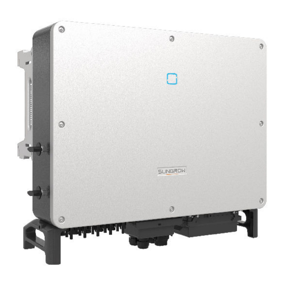
TN-C, TN-S, TN-C-S, TT, IT. The following figure shows the common grid configurations. In a TT power grid, the N-PE voltage should be lower than 30 V. Product Introduction Model Description The model description is as follows(Take SG30CX as an example) :... - Page 20 2 Product Description User Manual Appearance The following figure shows the appearance of the inverter. The image shown here is for reference only. The actual product received may differ. figure 2-2 Inverter Appearance Description Name To indicate the current working state of the inverter. LED indicator Mounting lugs To hang the inverter onto the mounting-bracket.
-
Page 21: Symbols On Product
User Manual 2 Product Description figure 2-3 Product Dimensions(in mm) *The image shown here is for reference only. The actual product you receive may differ. Type Dimensions (W*H*D) Weight SG30CX 50 kg SG30CX-NI 702×595×310 mm SG33CX 58 kg SG40CX 62 kg SG50CX 782×645×310 mm... -
Page 22: Led Indicator
2 Product Description User Manual Symbol Explanation CGC-SOLAR mark of conformity. Danger to life due to high voltages! Only qualified personnel can open and service the inverter. Disconnect the inverter from all the external power sources before maintenance! Burn danger due to the hot surface that may exceed 60°C. Do not touch live parts for 5 minutes after disconnection from the power sources. -
Page 23: Dc Switch
The DC switch is used to disconnect the DC current safely whenever necessary. The SG30CX-NI and SG50CX-NI is not equipped with DC switch. The SG30CX and SG33CX is equipped with one DC switch to control the connection and disconnection of all DC terminals. -
Page 24: Function Description
The communication accessory port is used to connect communication module manufactured by SUNGROW, and upload monitoring data by means of wireless communication. The inverter can be connected to communication devices via either of the two interfaces. - Page 25 User Manual 2 Product Description It is recommended to use the communication module from SUNGROW. Using a device from other companies may lead to communication failure or other unex- pected damage. The inverter can provide export control but will require the use of a external smart meter.
- Page 26 2 Product Description User Manual • Before enabling the PID recovery function, make sure the voltage polarity of the PV modules to ground meets requirement. If there are any questions, contact the PV module manufacturer or read the corresponding user manual. •...
-
Page 27: Unpacking And Storage
• Check the inner contents for damage after unpacking. Contact SUNGROW or the transport company in case of any damage or incompleteness, and provide photos to facilitate services. Do not dispose of the original packing case. It is recommended to store the device in the original packing case when the product is decommissioned. -
Page 28: Scope Of Delivery
3-1 Scope of Delivery a. The mounting-bracket includes 2 mounting-bracket components and 1 connecting bar. b. The SG30CX, SG30CX-NI, SG33CX, SG40CX, SG50CX, SG50CX-NI are respectively provided with 6, 6, 6, 8, 10, 10 pairs of DC connectors and cord end terminals. - Page 29 User Manual 3 Unpacking and Storage • If the inverter needs to be transported again, pack it strictly before loading and transport- ing it. • Do not store the inverter in places susceptible to direct sunlight, rain, and strong electric field.
-
Page 30: Mechanical Mounting
" " 4.2.1 Installation Environment Requirements" " . In case the environment where the device is installed does not meet the requirements, SUNGROW shall not be held liable for any prop- erty damage arising therefrom. Improper handling may cause personal injury! •... -
Page 31: Location Requirements
User Manual 4 Mechanical Mounting Location Requirements To a large extent, a proper installation location ensures safe operation, service life, and per- formance of the inverter. • The inverter with protection rating IP66 can be installed both indoors and outdoors. •... - Page 32 • Please consult SUNGROW before installing inverters outdoors in areas prone to salt damage, which mainly are coastal areas within 500 meters of the coast. The sedimenta- tion amount of salt spray is correlated to the characteristics of the seawater, sea winds, precipitation, air humidity, topography, and forest coverage in the adjacent sea areas, and there are substantial differences between different coastal areas.
-
Page 33: Carrier Requirements
User Manual 4 Mechanical Mounting 4.2.2 Carrier Requirements The mounting structure where the inverter is installed must comply with local/national stand- ards and guidelines. Ensure that the installation surface is solid enough to bear four times the weight of the inverter and is suitable for the dimensions of the inverter (e.g. cement walls, plasterboard walls, etc.). -
Page 34: Clearance Requirements
4 Mechanical Mounting User Manual In case the installation site is a level surface, mount the inverter to the bracket to meet the mounting angle requirements, as shown in the figure below. Take the following items into account when designing the bracket scheme: •... - Page 35 User Manual 4 Mechanical Mounting The distance between the bottom of the inverter and the ground surface is deter- mined according to the bending radius of the AC cable used and the installation environment. In addition, the following conditions must be met: •...
-
Page 36: Installation Tools
4 Mechanical Mounting User Manual Install the inverter at an appropriate height for ease of viewing LED indicator and operating switch(es). Installation Tools Installation tools include but are not limited to the following recommended ones. If necessary, use other auxiliary tools on site. table 4-1 Tool specification Goggles Earplugs... -
Page 37: Moving The Inverter
User Manual 4 Mechanical Mounting Wire cutter Wire stripper Hydraulic pliers Heat gun RJ45 crimping tool Crimping tool Connector wrench Multimeter 4–6mm ≥ 1100 Vdc Vacuum cleaner Moving the Inverter Before installation, remove the inverter from the packing case and move it to the installation site. -
Page 38: Manual Transport
4 Mechanical Mounting User Manual Improper handling may cause personal injury! • Arrange an appropriate number of personnel to carry the inverter according to its weight, and installation personnel should wear protective equipment such as anti-impact shoes and gloves. • Attention must be paid to the center of gravity of the inverter to avoid tilting dur- ing handling. -
Page 39: Installing Mounting-Bracket
User Manual 4 Mechanical Mounting Step 3 Hoist the inverter, and stop to check for safety when the inverter is 100mm above the ground. Continue hoisting the device to the destination after ensuring the safety. Step 4 Remove the lifting rings and reassemble the sealing screws released in Step 1. Keep the inverter balanced throughout the hoisting process and avoid collisions with walls or other objects. -
Page 40: Pv Bracket-Mounted Installation
4 Mechanical Mounting User Manual The expansion plug set shown below is recommended for the installation. figure 4-1 Dimensions of Mounting-bracket 4.5.1 PV Bracket-Mounted Installation Step 1 Assemble the mounting-bracket. Step 2 Level the assembled mounting-bracket by using the level, and mark the positions for drilling holes on the PV bracket. -
Page 41: Wall-Mounted Installation
User Manual 4 Mechanical Mounting Step 3 Secure the mounting-bracket with bolts. Components Description Mounting-bracket – Full threaded bolt M10*45 – Metal bracket – Flat washer Spring washer – – Hex nuts - - End 4.5.2 Wall-Mounted Installation Step 1 Assemble the mounting-bracket. Step 2 Level the assembled mounting-bracket by using the level, and mark the positions for drilling holes. -
Page 42: Installing The Inverter
4 Mechanical Mounting User Manual Step 3 Insert the expansion bolts into the holes and secure them with a rubber hammer. Fasten the nut with a wrench to expand the bolt. Remove the nut, spring washer, and flat washer, and store them properly. - Page 43 User Manual 4 Mechanical Mounting Step 4 Fix the inverter with screws. - - End...
-
Page 44: Electrical Connection
Electrical Connection Safety Instructions The PV string will generate lethal high voltage when exposed to sunlight. • Operators must wear proper personal protective equipment during electrical connections. • Must ensure that cables are voltage-free with a measuring instrument before touching DC cables. •... - Page 45 User Manual 5 Electrical Connection All electrical connections must comply with local and national/regional electrical standards. • Cables used by the user shall comply with the requirements of local laws and regulations. • Only with the permission of the national/regional grid department, the inverter can be connected to the grid.
-
Page 46: Terminal Description
* The image shown here is for reference only. The actual product received may differ. Item Terminal Mark Note MC4 PV connector SG30CX, SG30CX-NI, SG33CX: 6 pairs of terminals PV terminals + / - SG40CX: 8 pairs of terminals SG50CX, SG50CX-NI: 10 pairs of terminals For RS485 communication wiring. -
Page 47: Electrical Connection Overview
User Manual 5 Electrical Connection Item Terminal Mark Note Remove the protective case and use the junc- AC junction — tion box in the shipping accessory for wiring. External pro- tective use at least one of them to ground the inverter. grounding terminal Electrical Connection Overview... - Page 48 Other sizes of grounding cables that meet local standards and safety regulations can also be used for grounding connections. But SUNGROW shall not be held liable for any damage caused.
-
Page 49: Crimp Ot/Dt Terminal
User Manual 5 Electrical Connection Crimp OT/DT terminal Crimp OT/DT terminal 1. Heat shrink tubing 2. OT/DT terminal 3. Hydraulic pliers 4. Heat gun Aluminum Cable Requirements If an Aluminum cable is selected, use a copper to Aluminum adapter terminal to avoid direct contact between the copper bar and the Aluminum cable. -
Page 50: External Protective Grounding Connection
AC side grounding terminal are reliably grounded. The grounding connection can be made by other means if they are in accordance with the local standards and regulations, and SUNGROW shall not be held liable for the possible consequences. -
Page 51: External Protective Grounding Requirements
User Manual 5 Electrical Connection 5.5.1 External Protective Grounding Requirements All non-current carrying metal parts and device enclosures in the PV power system should be grounded, for example, brackets of PV modules and inverter enclosure. When there is only one inverter in the PV system, connect the external protective grounding cable to a nearby grounding point. - Page 52 AC Circuit Breaker An independent circuit breaker or fuse should be installed on the output side of the inverter to ensure safe disconnection from the grid. Recommended rated voltage Inverter Recommended rated current SG30CX SG33CX SG40CX 400V SG50CX 100A SG30CX-NI...
-
Page 53: Requirements For Ot/Dt Terminal
User Manual 5 Electrical Connection The inverter has not been tested to AS/NZS 4777.2:2020 for multiple inverter combinations. MV Transformer The MV transformer used together with the inverter should meet the following requirements: • A distribution transformer can be used if it is designed for the typical cyclical loads of a PV system (there is load in the day and no load at night). -
Page 54: Connection Procedure
5 Electrical Connection User Manual • Dimensions: a≤30mm / 8.4mm≤b≤10.5mm / c≤16mm 5.6.3 Connection Procedure High voltage may be present in inverter! Ensure all cables are voltage-free before electrical connection. Do not connect the AC circuit breaker until all inverter electrical connections are completed. - Page 55 User Manual 5 Electrical Connection Step 5 Unfasten the buckle and remove the protective cap. Step 6 Secure the wires to corresponding terminals. Observe the terminal layout on the block. Do not connect the phase wires to "PE" terminal or PE wire to "N" terminal. Otherwise, unrecoverable damage to the inver- ter may follow.
-
Page 56: Dc Cable Connection
5 Electrical Connection User Manual Step 7 Secure the junction box, fasten the buckle, and secure it with supplied M4×10 screw. Step 8 Gently pull the cable backwards to ensure firm connection, and fasten the swivel nut clockwise. - - End DC Cable Connection The PV string will generate lethal high voltage when exposed to sunlight. - Page 57 User Manual 5 Electrical Connection • Make sure the PV array is well insulated to ground before connecting it to the inverter. • Make sure the maximum DC voltage and the maximum short circuit current of any string never exceed inverter permitted values specified in "Technical Data". •...
-
Page 58: Pv Input Configuration
5.7.1 PV Input Configuration • As shown in the figure below, the inverter is provided with multiple PV inputs: PV inputs 1~n (SG30CX/SG30CX-NI/SG33CX/SG40CX/SG50CX/SG50CX-NI: n=3/3/3/4/5/5); and each PV input is designed with an MPP tracker. • Each PV input operates independently and has its own MPPT. In this way, string struc- tures of each PV input may differ from each other, including PV module type, number of PV modules in each string, angle of tilt, and installation orientation. -
Page 59: Assembling Pv Connectors
Use MC4-Evo2 DC terminals if the maximum input voltage is greater than 1,000 V. To purchase the MC4-Evo2 DC terminals, contact SUNGROW. • Select appropriate DC terminals as required above. Otherwise, SUNGROW shall be held no liability for the damage caused. To ensure IP66 protection, use only the supplied connector. - Page 60 5 Electrical Connection User Manual Step 3 Lead the cable through the cable gland, and insert the crimp contact into the insulator until it snaps into place. Gently pull the cable backward to ensure firm connection. Tighten the ca- ble gland and the insulator (torque 2.5 N.m to 3 N.m). Step 4 Check for polarity correctness.
-
Page 61: Installing Pv Connector
User Manual 5 Electrical Connection 5.7.3 Installing PV Connector Step 1 Rotate the DC switch to “OFF” position. The SG30/50CX-NI doesn't have a DC switch. Step 2 Check the cable connection of the PV string for polarity correctness and ensure that the open circuit voltage in any case does not exceed the inverter input limit of 1,100V. -
Page 62: Communication Junction Box
User Manual Step 5 Seal any unused PV terminal with a terminal cap. SUNGROW inverters cannot be used with third-party optimizers. If the PV string is equipped with the optimizer, please refer to the optimizer manual for elec- trical connections and make sure that the polarity of the optimizer cables is correct. -
Page 63: Communication Wiring Board
User Manual 5 Electrical Connection During installation, firmly press the junction box to ensure that the pin can be in- serted successfully. Never hit the pin with a heavy object, such a hammer. Otherwise, it will be irrecov- erably damaged. Communication Wiring Board The communication board of the inverter includes two layers. -
Page 64: Rs485 Communication System
5 Electrical Connection User Manual The RS485-1 crimp and the RJ45 interface can be applied to applications where multiple in- verters communicate in a daisy-chain form. A 120Ω resistor can be connected in parallel between RS485-1 A/B pins by configuring the dip switch. - Page 65 User Manual 5 Electrical Connection figure 5-5 Multi-inverter Connection When more than 15 inverters are connected to the same daisy chain, in order to ensure the communication quality, the Logger at the first end of the daisy chain needs to be equipped with a terminal resistor of 120Ω, the inverter at the last end needs to be equipped with a RS485-dip switch (SW1), and the shielding layer of the communication cable should be sin- gle-point grounded.
-
Page 66: Connection Procedure(Terminal Block)
5 Electrical Connection User Manual 5.10.3 Connection Procedure(Terminal Block) RS485 communication cables should be shielded twisted pair cables or shielded twisted pair Ethernet cables. There are three communication terminals, and the silkscreen marks are COM1/ COM2/COM3. Please choose according to the actual situation. Step 1 Remove the communication junction box, see"... -
Page 67: Connection Procedure (Rj45 Ethernet Port)
User Manual 5 Electrical Connection Step 5 Insert the terminal base into the corresponding terminal. table 5-3 Terminal definition Definition RS485 A IN, RS485A differential signal+ RS485 A OUT, RS485A differential signal+ RS485 B IN, RS485B differential signal- RS485 B OUT, RS485B differential signal- Step 6 If other wiring operations need to be performed on the communication board, finish the wiring operations before performing the following steps. - Page 68 5 Electrical Connection User Manual Step 2 Loosen the swivel nut of the junction box and select an appropriate seal according to cable outer diameter. Lead the cable through the swivel nut, seal, and junction box successively. Outer Diameter D(mm) Seal 4.5 ~ 6 6 ~ 12...
-
Page 69: Dry Contact Connection
User Manual 5 Electrical Connection Step 5 If other wiring operations need to be performed on the communication board, finish the wiring operations before performing the following steps. If otherwise, continue to perform the fol- lowing steps. Step 6 Install the junction box, see "... - Page 70 5 Electrical Connection User Manual DO terminal (fault output dry contact): The relay can be set to output fault alarms, and user can configure it to be a normally open contact (COM&NO) or a normally closed contact (COM&NC). The relay is initially at the NC contact, and it will trip to another contact when a fault occurs. When alarm occurs, signal status change will not be triggered.
- Page 71 User Manual 5 Electrical Connection figure 5-7 Normally open contact figure 5-8 Normally closed contact Devices connected to the relay should comply with related requirements: AC-Side Requirements DC-Side Requirements Max. voltage: 250 Vac Max. voltage: 30Vdc Max. current: 5A Max. current: 5A DI terminal (emergency stop dry contact): the dry contact can be configured to be an emergency stop contact.
-
Page 72: Wiring Procedure
5 Electrical Connection User Manual figure 5-9 Local stop contact figure 5-10 Daisy chain topology When wiring DI dry contacts, ensure that the maximum wiring distance meet the require- "10.2 Wring Distance of DI Dry ments in Contact". 5.11.2 Wiring Procedure Refer to the wiring of terminal block described in chapter"5.10.3 Connection Procedure(Ter- minal Block)"... -
Page 73: Connection Procedure
20kΩ Enable the DRM function through the iSolarCloud APP. If there are any problems, contact your distributor first. If the problem persists, contact SUNGROW. The DRM function is only applicable to devices for Australia and New Zealand. 5.12.2 Connection Procedure Step 1 Remove the communication junction box, see"... - Page 74 5 Electrical Connection User Manual Step 3 Loosen the swivel nut and select an appropriate seal according to cable outer diameter. Lead the cable through the swivel nut, and seal successively. Outer Diameter D Seal (mm) 4.5 ~ 6 6 ~ 12 a + b 12 ~ 18 Step 4 Insert the RJ45 connector to the RJ45 jack.
-
Page 75: Communication Module Connection (Optional)
- - End 5.13 Communication Module Connection (optional) Connect the communication module produced by SUNGROW to the communication acces- sory port. After successful connection, information such as power generation and running state of the inverter can be viewed via the App on the phone. -
Page 76: Commissioning
Commissioning Inspection Before Commissioning Check the following items before starting the inverter: • All equipment has been reliably installed. • DC switch(es) and AC circuit breaker are in the "OFF" position. • The ground cable is properly and reliably connected. •... - Page 77 User Manual 6 Commissioning Step 3 Connect the DC switch(if there is) between the inverter and the PV string. "7.2 In- Step 4 Set initial protection parameters via the iSolarCloud App. For details, please refer to "7.4.2 Login stalling App",and Procedure".
-
Page 78: Isolarcloud App
iSolarCloud App Brief Introduction The iSolarCloud App can establish communication connection to the inverter via the Blue- tooth, thereby achieving near-end maintenance on the inverter. Users can use the App to view basic information, alarms, and events, set parameters, or download logs, etc. *In case the communication module Eye, WiFi or WiNet-S is available, the iSolarCloud App can also establish communication connection to the inverter via the mobile data or WiFi, thereby achieving remote maintenance on the inverter. -
Page 79: Function Overview
User Manual 7 iSolarCloud App Function Overview The App provides parameter viewing and setting functions, as shown in the following figure. figure 7-1 App Function Tree Map Login 7.4.1 Requirements The following requirements should be met: • The AC or DC side of the inverter is powered-on. •... - Page 80 7 iSolarCloud App User Manual Step 2 Establish the Bluetooth connection by either of the two following ways. If the LED indicator flashes blue, the connection is successfully established. • Scan the QR code on the side of the inverter for Bluetooth connection. •...
- Page 81 The Account is “user”, and the initial password is "pw1111" or "111111" which should be changed for the consideration of account security. To set inverter parameters related to grid protection and grid support, contact SUNGROW to obtain the advanced account and corresponding password.
- Page 82 In the Brazilian region, set the country code as "Brazil". Selecting "Brazil_230" or "Brazil_240" will cause setting failure. For SG30CX, set the grid code as EN50549 in the Ukraine region and apply man- ual settings for country code compliance.
- Page 83 User Manual 7 iSolarCloud App Step 5 When the country is set to Australia, additionally set the applicable network service provider and then the grid type.Tap Power Company to select the correct power company. figure 7-5 Initialization Power Company The image shown here is for reference only. Refer to the actual interface for the supported network service providers.
-
Page 84: Home
7 iSolarCloud App User Manual Grid Type Network Service Provider SA Power Networks • TS129-2019: < 10 kW for single-phase & 30 kW for three-phase • TS130-2017: > 30 kW & ≤ 200 kW • TS131-2018: > 200 kW Horizon Power •... - Page 85 User Manual 7 iSolarCloud App figure 7-6 Home Page table 7-2 Home Page Description Designation Description System date and time of the inverter Date and time Present operation state of the inverter. For details, refer to Inverter state "table 7-3 Description of Inverter State".
-
Page 86: Run Information
7 iSolarCloud App User Manual table 7-3 Description of Inverter State Description State After being energized, inverter tracks the PV arrays’ maximum power point (MPP) and converts the DC power into AC power. This is the nor- mal operation mode. Stop Inverter is stopped. - Page 87 User Manual 7 iSolarCloud App table 7-5 Run Information Classifica- Description Parameter tion String n Voltage The input voltage of the n string Information String n current The input current of the n string Total On-grid Run- ning Time Daily On-grid Run- ning Time Negative Voltage to Inverter DC side negative to ground voltage value...
-
Page 88: View Records
7 iSolarCloud App User Manual Classifica- Description Parameter tion Phase C Current View Records Tap Records on the navigation bar to enter the interface showing event records, as shown in the following figure. figure 7-7 Records Fault Alarm Record Tap Fault Alarm Record to enter the interface, as shown in the following figure. figure 7-8 Fault Alarm Record to select a time segment and view corresponding records. - Page 89 User Manual 7 iSolarCloud App figure 7-9 Detailed Fault Alarm Information Yield Record Tap Yield Record to enter the interface showing daily power generation as shown in the fol- lowing figure. figure 7-10 Power Curve The App displays power generation records in a variety of forms, including daily power gen- eration graph, monthly power generation histogram, annual power generation histogram.
-
Page 90: More
7 iSolarCloud App User Manual Description Parameter Monthly yield Shows the power output every month in a year. histogram Annual yield Shows the power output every year. histogram Tap the time bar on the top of the interface to select a time segment and view the corre- sponding power curve. -
Page 91: Operation Parameters
User Manual 7 iSolarCloud App figure 7-12 System Parameters * The image shown here is for reference only. Boot/Shutdown Tap Boot/Shutdown to send the boot/shutdown instruction to the inverter. For Australia and New Zealand, when the DRM state is DRM0, the "Boot" option will be prohibited. - Page 92 7 iSolarCloud App User Manual figure 7-14 PID Parameters table 7-7 PID Parameter Description Description Parameter Enabling/Disable the PID night recovery function. Once enabled, it PID Recovery works between 22:00 pm and 5:00 am by default. If ISO impedance abnormality or PID function exception is de- tected during running of the PID function, the inverter reports a Clear PID alarm PID abnormity and reminds the user to take corresponding meas-...
-
Page 93: Power Regulation Parameters
User Manual 7 iSolarCloud App figure 7-16 NS Protection(Passive Valid) 7.8.3 Power Regulation Parameters Active Power Regulation Tap “Settings→Power Regulation Parameters→Active Power Regulation” to enter the screen, as shown in the following figure. figure 7-17 Active Power Regulation table 7-8 Active Power Regulation Definition/Setting Range Parameter... - Page 94 7 iSolarCloud App User Manual Definition/Setting Range Parameter Description Active power rising The rise rate of inverter active 1%/min~6000%/min gradient power per minute. Active power setting Switch for enabling/disabling Enable/Disable persistence the function of saving output limited power. Active power limit The switch for limiting output Enable/Disable power.
- Page 95 User Manual 7 iSolarCloud App figure 7-18 Reactive Power Regulation table 7-9 Reactive Power Regulation Definition/Setting Range Parameter Description Reactive power genera- Switch for enabling/disabling Enable/Disable tion at night Q at night function. Reactive power ratio at Reactive power ratio set for -100%~0%/ night the Q at night function.
- Page 96 7 iSolarCloud App User Manual Definition/Setting Range Parameter Description QP_P3 Output power at P3 on the Q 20.0%~100.0% (P) mode curve (in percentage) QP_K1 Power factor at P1 on the Q(P) Curve A/Curve mode curve C:0.800~1.000 Curve B: [-0.600~0.600]*Ac- tive Overload Rate/1000 QP_K2 Power factor at P2 on the Q(P) Curve A/Curve C:...
- Page 97 User Manual 7 iSolarCloud App Definition/Setting Range Parameter Description QU_V2 Pre-set grid voltage U2 that is 80.0%~100.0% reactive according to the grid voltage. QU_Q2 Pre-set proportion of reactive [-60.0%-60.0%]* Overload power according to the grid Rate/1000 voltage U2. QU_V3 Pre-set grid voltage U3 that is 100.0%~120.0% reactive according to the grid voltage.
-
Page 98: Communication Parameters
7 iSolarCloud App User Manual figure 7-19 Q(U) Curve figure 7-20 Q(P) Curve 7.8.4 Communication Parameters Tap “Settings→Communication Parameters” to enter the corresponding screen, as shown in the following figure. The device address ranges from 1 to 246. figure 7-21 Communication Parameters 7.8.5 Firmware Update To avoid download failure due to poor on-site network signal, it is recommended to download the firmware package to the mobile device in advance. -
Page 99: Grounding Detection
If the distributor is unable to provide the required information, contact SUNGROW. Unauthorized personnel are not allowed to log in with this account. Otherwise, SUNGROW shall not be held liable for any damages caused. Tap “More→Settings→Operation Parameters→Grounding Detection” to enter the corre- sponding screen. -
Page 100: Password Changing
7 iSolarCloud App User Manual figure 7-22 Grounding Detection If the grounding detection is enabled, the DO relay will switch on automatically to signal the external alarm if the value exceeds the grounding detection alarm value. The PV insulation resistance fault (fault sub-code 039) will trigger the DO relay to signal the external alarm. -
Page 101: System Decommissioning
System Decommissioning Disconnecting Inverter Danger of burns! Even if the inverter is shut down, it may still be hot and cause burns. Wear protec- tive gloves before operating the inverter after it cools down. For maintenance or other service work, the inverter must be switched off. Proceed as follows to disconnect the inverter from the AC and DC power sources. -
Page 102: Disposal Of Inverter
8 System Decommissioning User Manual Step 1 Refer to "5 Electrical Connection", for the inverter disconnection of all cables in reverse steps. In particular, when removing the DC connector, use an MC4 wrench to loosen the locking parts and install waterproof plugs. Step 2 Refer to"4 Mechanical Mounting", to dismantle the inverter in reverse steps. -
Page 103: Troubleshooting And Maintenance
App or the LCD. Modify the overvoltage protection values with the con- sent of the local electric power operator. 3. Contact Sungrow Customer Service if the pre- ceding causes are ruled out and the fault persists. Generally, the inverter will be reconnected to the grid after the grid returns to normal. - Page 104 2. Check whether the protection parameters are appropriately set via the App or the LCD. 3. Contact Sungrow Customer Service if the pre- ceding causes are ruled out and the fault persists. Generally, the inverter will be reconnected to the grid after the grid returns to normal.
- Page 105 App or the LCD. 3. Contact Sungrow Customer Service if the pre- ceding causes are ruled out and the fault persists. 1. Check whether the corresponding string is of reverse polarity.
- Page 106 3. Check if the DC fuse is damaged. If so, replace Alarm the fuse. 4. Contact Sungrow Customer Service if the pre- ceding causes are ruled out and the alarm persists. *The code 548 to code 563 are corresponding to string 1 to string 16 respectively.
- Page 107 If so, replace the dam- aged cable and secure terminals to ensure a reli- able connection. 5. Contact Sungrow Customer Service if the pre- ceding causes are ruled out and the fault persists. 1. Check whether the AC cable is correctly connected.
- Page 108 2. Reconnect the communication cable of the cation Abnormal meter. Alarm 3. Contact Sungrow Customer Service if the pre- ceding causes are ruled out and the alarm persists. 1. Check whether the output port is connected to actual grid. Disconnect it from the grid if so.
- Page 109 Close the AC and DC switches in turn 15 248–255, 300– minutes later and restart the system. 322, 324–328, 3. Contact Sungrow Customer Service if the pre- 401–412, 600– ceding causes are ruled out and the fault persists. 603, 605, 608, 612, 616, 620, 622–624, 800,...
- Page 110 Close the AC and DC switches in turn 15 364-395 Overvoltage Fault minutes later and restart the system. 2. If the fault persists, please contact Sungrow Power Customer Service. 1. Check whether the number of PV modules of the corresponding string is less than other strings.
- Page 111 1. Check whether the alarm still exists after this Output voltage ex- alarm is cleared. overvolt- ceeds the 2. If the alarm persists, please contact Sungrow set limit Customer Service. value The input 1. Check whether the alarm still exists after this current ex- alarm is cleared.
- Page 112 If there is a string current backfeed fault, first check whether the optimizer is offline. • Contact the dealer if the measures listed in the “Troubleshooting Method” col- umn have been taken but the problem persists. Contact SUNGROW if the dealer fails to solve the problem.
-
Page 113: Maintenance
To avoid the risk of electric shock, do not perform any other maintenance opera- tions beyond this manual. If necessary, contact your distributor first. If the problem persists, contact SUNGROW. Otherwise, the losses caused is not covered by the warranty. -
Page 114: Routine Maintenance
9 Troubleshooting and Maintenance User Manual Touching the PCB or other static sensitive components may cause damage to the device. • Do not touch the circuit board unnecessarily. • Observe the regulations to protect against electrostatic and wear an anti-static wrist strap. -
Page 115: Cleaning Air Inlet And Outlet
User Manual 9 Troubleshooting and Maintenance 9.2.3 Cleaning Air Inlet and Outlet A significant amount of heat is generated when the inverter is working. In order to maintain good ventilation, please check to make sure the air inlet and outlet are not blocked. - Page 116 9 Troubleshooting and Maintenance User Manual Step 3 Press the tab of the latch hook, unplug the cable connection joint outwards, and loosen the screw on the fan holder. Step 4 Pull out the fan module, clean the fans with soft brush or vacuum cleaner, and replace them when necessary.
-
Page 117: Appendix
10 Appendix 10.1 Technical Data SG30CX SG33CX Parameters Input (DC) 1100 V Max. PV input voltage Min. PV input voltage / 200 V / 250 V Start-up input voltage Nominal PV input voltage 585 V MPP voltage range 200 V ~ 1000 V... - Page 118 10 Appendix User Manual SG30CX SG33CX Parameters Efficiency Max. efficiency / Euro- 98.6% / 98.3% pean efficiency Protection reverse polarity protection AC short circuit protection Leakage current protection Grid monitoring Ground fault monitoring DC switch AC switch PV string monitoring...
- Page 119 User Manual 10 Appendix SG30CX SG33CX Parameters OT or DT terminal (Max.70 mm AC connection type Q at night function, LVRT, HVRT, active & reactive power con- Grid Support trol and power ramp rate control Note(1): The inverter enters the standby state when the input voltage ranges between 1,000 V and 1,100 V.
- Page 120 10 Appendix User Manual SG40CX SG50CX Parameters < 3 % (at nominal power) Harmonic (THD) < 0.5 % In DC current injection Power factor at nominal > 0.99 / 0.8 leading ~ 0.8 lagging power / Adjustable power factor Feed-in phases / AC connection Efficiency Max.
- Page 121 • The voltage difference between MPPTs should be less than 80 V. • The voltage of the configured string should be higher than the lower limit of the rated MPPT voltage. SG30CX SG50CX Parameters Input (DC) Recommended max. PV 45 kW...
- Page 122 10 Appendix User Manual SG30CX SG50CX Parameters 200 A (40 A / 40 A / 40 A / Max. DC short-circuit 120 A (40 A / 40 A / 40 A) 40 A / 40 A) current Output (AC) AC output power 29.9 kVA...
- Page 123 User Manual 10 Appendix SG30CX SG50CX Parameters DC Type II / AC Type II Surge Protection Protective Class Overvoltage Category DC II / AC III Active Anti-Islanding Frequency Shift Method General Data 702×595×310mm 782×645×310 mm Dimensions (W×H×D) 50 kg 62 kg...
- Page 124 10 Appendix User Manual Parameters SG30CX-NI SG50CX-NI Input (DC) Recommended max. PV 45kW 76kW input power 1100 V Max. PV input voltage Min. PV input voltage / 200 V / 250 V Start-up input voltage Nominal PV input voltage 585 V...
- Page 125 User Manual 10 Appendix Parameters SG30CX-NI SG50CX-NI DC reverse polarity pro- tection AC short circuit protection Leakage current protection Grid monitoring Ground fault monitoring (10) DC switch AC switch PV string monitoring Q at night function PID recovery function DC Terminal Protective...
-
Page 126: Wring Distance Of Di Dry Contact
10 Appendix User Manual connectors included in the scope of delivery must not be used. In this case MC4 Evo2 con- nectors must be used. Note(9): • The voltage difference between MPPTs should be less than 80 V. • The voltage of the configured string should be higher than the lower limit of the rated MPPT voltage. -
Page 127: Quality Assurance
• The customer shall give SUNGROW a reasonable period to repair the faulty device. Exclusion of Liability In the following circumstances, SUNGROW has the right to refuse to honor the quality guarantee: • The free warranty period for the whole machine/components has expired. -
Page 128: Contact Information
The fault or damage is caused by installation, repairs, modification, or disassembly per- formed by a service provider or personnel not from SUNGROW. • The fault or damage is caused by the use of non-standard or non-SUNGROW compo- nents or software. •... - Page 129 Sungrow Power Supply Co., Ltd. www.sungrowpower.com...
Need help?
Do you have a question about the SG30CX and is the answer not in the manual?
Questions and answers