Sungrow SG33CX User Manual
Pv grid-connected inverter
Hide thumbs
Also See for SG33CX:
- User manual (95 pages) ,
- User manual (109 pages) ,
- User manual (113 pages)

Related Manuals for Sungrow SG33CX


Summary of Contents for Sungrow SG33CX
- Page 1 User Manual SG33CX SG40CX SG50CX PV Grid-Connected Inverter SG33_40_50CX-UEN-Ver11-201907 Version: 1.1...
- Page 3 Software Licenses It is prohibited to use data contained in firmware or software developed by SUNGROW, in part or in full, for commercial purposes by any means. It is prohibited to perform reverse engineering, cracking, or any other operations that compromise the original program design of the software developed by SUNGROW.
- Page 4 Validity This manual is valid for the following inverter types: SG33CX SG40CX SG50CX They will be referred to as “inverter” hereinafter unless otherwise specified. Target Group ...
- Page 5 Symbol Explanation Indicates a hazard with a high level of risk that, if not avoided, will result in death or serious injury. Indicates a hazard with a medium level of risk that, if not avoided, could result in death or serious injury. Indicates a hazard with a low level of risk that, if not avoided, could result in minor or moderate injury.
-
Page 6: Table Of Contents
Contents About This Manual ..............II Safety ..................1 PV modules ................1 Utility Grid .................. 1 Inverter ..................2 Skills of Qualified Personnel ............3 Product Introduction ............4 Intended Usage ................. 4 Product Introduction ..............5 2.2.1 Type Description ................ 5 2.2.2 Appearance ................ - Page 7 Installation Tools ..............18 Moving the Inverter ..............20 4.4.1 Manual Transport ..............20 4.4.2 Hoisting Transport ..............21 PV Bracket-Mounted Installation ..........22 4.5.1 Preparation before Mounting ........... 22 4.5.2 Mounting Steps................ 22 Wall-Mounted Installation ............24 4.6.1 Preparation before Mounting ........... 24 4.6.2 Mounting Steps................
- Page 8 5.9.3 Connection Procedure ............. 46 5.10 Dry Contact Connection ............50 5.10.1 Dry Contact Function ............. 50 5.10.2 Wiring Procedure ..............53 5.11 Communication Module Connection (optional) ......53 Commission ...............54 Inspection before Commissioning ........... 54 Commissioning Procedure ............54 iSolarCloud APP ..............55 Brief Introduction ..............
- Page 9 9.2.2 Maintenance Instruction ............78 10 Appendix ................81 10.1 Technical Data ................. 81 10.2 Quality Assurance ..............83 10.3 Contact Information ..............84...
-
Page 11: Safety
The safety instructions in this manual cannot cover all the precautions that should be followed. Perform operations considering actual onsite conditions. SUNGROW shall not be held liable for any damage caused by violation of the safety instructions in this manual. 1.1 PV modules PV strings will produce electrical power when exposed to sunlight and can cause a lethal voltage and an electric shock. -
Page 12: Inverter
1 Safety User Manual All electrical connections must be in accordance with local and national standards. Only with the permission of the utility grid, the inverter can be connected to the utility grid. 1.3 Inverter Danger to life from electric shocks due to live voltage ... -
Page 13: Skills Of Qualified Personnel
User Manual 1 Safety Only qualified personnel can perform the country setting. Unauthorized alteration of the country setting may cause a breach of the type-certificate marking. Risk of inverter damage due to electrostatic discharge (ESD). By touching the electronic components, you may damage the inverter. For inverter handling, be sure to: ... -
Page 14: Product Introduction
Item Description Note Monocrystalline silicon, polycrystalline silicon and PV strings thin-film without grounding. Inverter SG33CX, SG40CX, SG50CX. Grid Includes devices such as AC circuit breaker, SPD, connection metering device. cabinet Boost the low voltage from inverter to grid-compatible Transformer... -
Page 15: Product Introduction
L1 L2 L3 N PE Inverter Inverter 2.2 Product Introduction 2.2.1 Type Description The device type description is as follows (Take SG33CX as an example): Code of Product Series Code Of power level Photovoltaic grid-connected inverter Tab. 2-1 Power Level Description... -
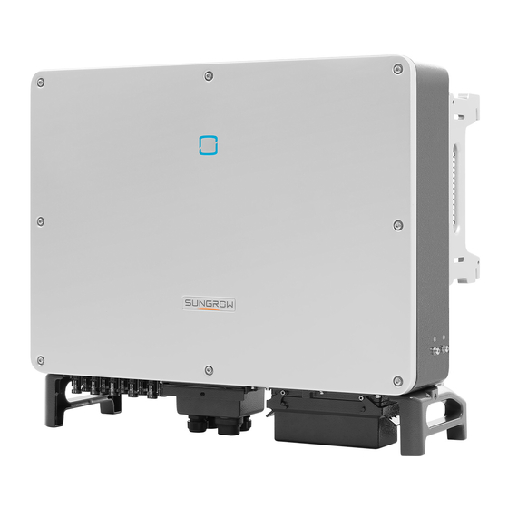
Page 16: Appearance
2 Product Introduction User Manual 2.2.2 Appearance *The image shown here is for reference only. The actual product you receive may differ. Name Description HMI interface to indicate the present working state LED indicator panel of the inverter. used hang inverter onto Mounting ears... -
Page 17: Dimensions
2 Product Introduction 2.2.3 Dimensions Depth Width Height Fig. 2-2 Dimensions of the Inverter Type Dimensions (W*H*D) Weight SG33CX 50 kg 702×595×310mm SG40CX 58 kg 782×645×310mm SG50CX 62kg 2.2.4 LED Indicator Panel As an HMI, the LED indicator panel on the inverter front panel indicates the present working state of the inverter. -
Page 18: Dc Switch
The DC switch is used to disconnect the DC current safely whenever necessary. The SG33CX is equipped with one DC switch to control the connection and disconnection of all DC terminals. The SG40CX and SG50CX are equipped with two DC switches separately controlling a group of DC inputs. -
Page 19: Function Description
− The communication accessory port is used to connect communication module manufactured by SUNGROW such as Eye and WiFi, and upload monitoring data to background by means of wireless communication such as Bluetooth, WiFi or wireless network. - Page 20 2 Product Introduction User Manual PID function After the PID function is enabled, the voltage to ground of all PV modules is greater than 0, that is, the PV module-to-ground voltage is a positive value. Transformer PV moudle Inverter Grid Rise the to-ground electromotive force at the negative pole of the PV moidle Before enabling the PID recovery function, make sure the voltage...
-
Page 21: Unpacking And Storage
Unpack and check inner contents for damage. Check the delivery scope for completeness according to the packing list. Contact SUNGROW or the distributor in case there is any damage or incompleteness Do not dispose of the original packing case. It is recommended to store the inverter in it. - Page 22 Enclosure 工作温度范围 Ambient Temperature -30℃ ... +60℃ 阳 光 电 源 股 份 有 限 公 司 SUNGROW POWER SUPPLY CO., LTD. 中国制造 www.sungrowpower.com Made in China Fig. 3-1 Nameplate * The image shown here is for reference only. The actual product you receive may differ.
-
Page 23: Scope Of Delivery
The mounting-bracket includes 2 mounting-bracket components and 1 connecting bar. b: The SG33CX, SG40CX, and SG50CX are respectively provided with 6, 8, and 10 pairs of DC connectors and cord end terminals. c: The screws include 1 M4×25 screw, 3 M4×10 screws, and 2 M6×65 screws. - Page 24 3 Unpacking and Storage User Manual The storage temperature should be always between -40° C and +70° C, and the storage relative humidity should be always between 0 and 95 %, non-condensing. In case of stacking storage, the number of stacking layers should never exceed the limit marked on the outer side of the packing case.
-
Page 25: Mechanical Mounting
4 Mechanical Mounting 4.1 Safety during Mounting Make sure there is no electrical connection before installation. In order to avoid electric shock or other injury, be sure there is no electricity or plumbing installations before drilling holes. Risk of injury due to improper handling ... -
Page 26: Installation Environment Requirements
4 Mechanical Mounting User Manual 4.2.1 Installation Environment Requirements The installation environment is free of inflammable or explosive materials. The inverter should be installed in a place inaccessible to the children. The ambient temperature and relative humidity should meet the following requirements. -
Page 27: Installation Clearance Requirements
User Manual 4 Mechanical Mounting In case the installation site is a level surface, mount the inverter to the horizontal-mounting bracket meet mounting angle requirements, as shown in the figure below. Distance away from ground surface ≥ 300mm Distance away from floating surface ≥ 650mm (Floating system) Cable binding position Take the following items into account when designing the bracket... -
Page 28: Installation Tools
4 Mechanical Mounting User Manual ≥500mm ≥600mm ≥200mm ≥1000mm ≥650mm In case of multiple inverters, reserve specific clearance between the inverters. ≥600mm ≥600mm ≥600mm ≥200mm In case of back-to-back installation, reserve specific clearance between the two inverters. ≥500mm ... - Page 29 User Manual 4 Mechanical Mounting Type Tool Packaging Marker Measuring tape Level tape Utility knife Multimeter Protective Wrist strap Measurement clothing ≥ range: 1100Vdc 880.0 General tools Protective Dust mask Earplugs Goggles gloves Insulated Vacuum shoes cleaner Hammer drill Rubber mallet Slotted Phillips Drill bit: φ12,...
-
Page 30: Moving The Inverter
4 Mechanical Mounting User Manual Type Tool crimping tool RJ45 crimping Wire stripper Hydraulic pliers tool Other auxiliary tools that may be used 4.4 Moving the Inverter Move the inverter to the specified position before installation. The inverter can be moved manually or via a hoist. -
Page 31: Hoisting Transport
User Manual 4 Mechanical Mounting 4.4.2 Hoisting Transport Release the sealing screws on the mounting ears and store them Step 1 properly. Anchor two M12 thread lifting rings to the hangers of the inverter. Step 2 Lead the sling through the two lifting rings and fasten the tie-down strap. Step 3 Step 4 Hoist the inverter, and stop to check for safety when the inverter is... -
Page 32: Pv Bracket-Mounted Installation
4 Mechanical Mounting User Manual The lifting rings and the sling are not within the delivery scope. 4.5 PV Bracket-Mounted Installation 4.5.1 Preparation before Mounting Tools Item Specification Phillips screwdriver/ M4, M6 electric screw driver Marker Level Drill bit: φ12 Hammer drill Socket wrench Including 16mm socket... - Page 33 User Manual 4 Mechanical Mounting Secure the mounting-bracket with bolts. Step 3 16mm 35N.m Tab. 4-1 Fastening sequence Components Description Mounting-bracket Full threaded bolt M10*45 Metal bracket Flat washer Spring washer Hex nuts Take out the inverter from the packing case. Step 4 Hoist the inverter to the installation position when necessary (refer to Step 5...
-
Page 34: Wall-Mounted Installation
4 Mechanical Mounting User Manual Fix the inverter with two M6×65 screws. Step 7 4.5N.m 4.6 Wall-Mounted Installation 4.6.1 Preparation before Mounting Tools Item Specification Phillips screwdriver/ M4, M6 electric screw driver Marker Level Drill bit(Select according expansion bolt Hammer drill specifications) Socket wrench Including 16mm socket... -
Page 35: Mounting Steps
User Manual 4 Mechanical Mounting Spare parts Item Quantity Specification Source Delivery scope M4×10 Grub screw Delivery scope M6×65 × Expansion bolts Self-prepared (Recommended) 4.6.2 Mounting Steps Assemble the mounting-bracket by using the connecting bar. Step 1 1.5N.m Level the assembled mounting-bracket by using the level, and mark the Step 2 positions for drilling holes on the installation site. - Page 36 4 Mechanical Mounting User Manual 16mm 35N.m Tab. 4-2 Fastening sequence Item Designation Description Wall Fastening the bolt in the sequence of nut, spring Expansion bolt washer, slat washer Mounting-bracket Take out the inverter from the packing case. Step 5 Hoist the inverter to the installation position when necessary (refer to Step 6 4.4.2 Hoisting Transport).
- Page 37 User Manual 4 Mechanical Mounting 4.5N.m...
-
Page 38: Electrical Connection
5 Electrical Connection 5.1 Safety Instructions High voltage may be present inside the inverter! The PV string will generate lethal high voltage when exposed to sunlight. Do not connect AC&DC circuit breakers before finishing electrical connections. Ensure all cables are voltage free before performing cable connection. ... -
Page 39: Electrical Connection Overview
* Figure shown here is for reference only. The actual product you receive may differ Item Terminal Mark Note MC4 PV connector SG33CX: 6 pairs of terminals PV terminals + / - SG40CX: 8 pairs of terminals SG50CX: 10 pairs of terminals For RS485 communication, digital input COM1... - Page 40 5 Electrical Connection User Manual Inverter Item Designation PV string Grid Monitoring device AC circuit breaker Tab. 5-1 Cable requirements Specification Outer Cable Type Cross section diameter (mm) PV cable complying DC cable with 1,500V standard Additional The same as that Outdoor single-core Grounding of the PE wire in...
-
Page 41: Additional Grounding Connection
User Manual 5 Electrical Connection Tab. 5-2 PE wire requirements Phase wire cross section PE wire cross Note section specifications 16 mm 16<S≤35mm valid only when the phase wire and PE wire use the same material. otherwise, ensure that the cross section of the PE S>35 mm wire... -
Page 42: Ac Cable Connection
5 Electrical Connection User Manual L = E + (2~3)mm 1: Heat shrink tubing 2: OT/DT terminal Fasten the cable with a screwdriver. Step 2 4.2~4.5N.m There are two grounding terminals. Use at least one of them to ground the inverter. 5.5 AC Cable Connection 5.5.1 AC Side Requirements Before connecting the inverter to the grid, ensure the grid voltage and... - Page 43 If multiple inverters are connected in parallel to the grid, ensure that the total number of parallel inverters does not exceed 30. Otherwise, please contact SUNGROW for technical scheme. MV transformer The MV transformer used together with the inverter should meet the following requirements: ...
-
Page 44: Requirement For Ot/Dt Terminal
The apparent power of the inverter should never exceed the power of the transformer. The maximum AC current of all inverters connected in parallel must be taken into account. If more than 30 inverters are connected to the grid, contact SUNGROW. The transformer must be protected against overloading and short circuit. -
Page 45: Aluminium Cable Requirements
User Manual 5 Electrical Connection Fig. 5-2 Dimensions of Terminal 5.5.3 Aluminium Cable Requirements If an aluminium cable is selected, use a copper to aluminium adapter terminal to avoid direct contact between the copper bar and the aluminium cable. Aluminium adapter terminal Flange nut... - Page 46 5 Electrical Connection User Manual Outer Diameter: D Outer diameter Seals D(mm) 20~25 a+b+c+d 25~30 a+b+c 30~40 40~50 Strip the protection layer and insulation layer by specific length, as Step 3 described in the figure below. L = E + (2~3)mm ≤135mm Make the cable and crimp OT terminal.
- Page 47 User Manual 5 Electrical Connection Secure the cable to corresponding terminals. Step 6 Note the terminal positions of PE wire and N wire. If a phase wire is connected to the PE terminal or N terminal, unrecoverable damage may be caused to the inverter.
-
Page 48: Pv String Connection
5 Electrical Connection User Manual 72mm 8~12N.m 5.6 PV String Connection Electric shock! The PV array will generate lethal high voltage once exposed to sunlight. Make sure the PV array is well insulated to ground before connecting it to the inverter. There is a risk of inverter damage! The following requirements should be met. - Page 49 *SG33/40/50CX: n= 3/4/5 Open circuit voltage Type Max. current for input connector limit SG33CX 1,100V SG40CX 1,100V SG50CX 1,100V DC cable on the PV string side should be connected via the PV connector which is included in the scope of delivery.
-
Page 50: Connection Procedure
5 Electrical Connection User Manual To ensure IP66 protection, use only the connector within the scope of delivery or the connector with the same ingress of protection. 5.6.2 Connection Procedure High voltage may be present in the inverter! Ensure all cables are voltage-free before performing electrical operations. ... -
Page 51: Installing The Pv Connectors
User Manual 5 Electrical Connection Check for polarity correctness. Step 4 5.6.3 Installing the PV Connectors Rotate the DC switch to "OFF" position. Step 1 Check the cable connection of the PV string for polarity correctness and Step 2 ensure that the open circuit voltage in any case does not exceed the inverter input limit of 1,100V. -
Page 52: Communication Junction Box
5 Electrical Connection User Manual Seal the unused PV terminals with MC4 terminal caps. Step 5 5.7 Communication Junction Box 5.7.1 Remove the Junction Box Pull out the pin and keep it properly, remove the junction box. Step 1 The pin removed is a required accessory for fixing the junction box. Store it properly and protect it against missing or deformation. -
Page 53: Communication Wiring Board
User Manual 5 Electrical Connection During installation, press the junction box forcibly to ensure that the pin can be inserted successfully. Never hit the pin with a heavy object, such a hammer. Otherwise, it will be irrecoverably. 5.8 Communication Wiring Board The communication board of the inverter includes two layers. -
Page 54: Rs485 Communication System
5 Electrical Connection User Manual RS485-1 interface (RJ45) RS485-1 dip switch RS485 120ohm A1 A1 B1 B1 RS485-1interface RS485-2 interface (terminal block) All the three interfaces can be connected to a data acquisition device (Logger), to achieve data exchange with PC or other monitoring devices. The RS485-2 interface can only be applied to the application scenario of single inverter communication. - Page 55 User Manual 5 Electrical Connection RS485 Inverter 120ohm A1 A1 B1 B1 ON OFF Logger Multi-inverter communication system In case of multiple inverters, all the inverters can be connected via RS485 cables in the daisy chain manner. RJ45 RJ45 RJ45 Terminal Block Terminal Block Terminal Block...
-
Page 56: Connection Procedure
5 Electrical Connection User Manual the shielding layer of the communication cable should be single-point grounded. 120ohm 120ohm 120ohm Inverter Inverter 2~(N-1) Inverter N Monitoring station Logger Fig. 5-4 Terminal resistor state(N≥15) The length of the RS485 cable should be no longer than 1,200m. ... - Page 57 User Manual 5 Electrical Connection Outer diameter Seal D(mm) 4.5~6 6~12 13~18 Strip the protection layer and insulation layer by appropriate length. Step 3 7 mm 20 mm Secure the cable to the terminal base. Step 4 0.2 N.m Insert the terminal base into the corresponding terminal. Step 5 Tab.
- Page 58 5 Electrical Connection User Manual Pull the cable gently to make sure it is secured, tighten the swivel nut Step 8 clockwise. 33mm 5~6 N.m RJ45 network port Remove the communication junction box, see 5.7.1 Remove the Step 1 Junction Box. Strip the insulation layer of the Ethernet cable with a wire stripper, and Step 2 insert the signal wires to the RJ45 connector.
- Page 59 User Manual 5 Electrical Connection Outer diameter Seal D(mm) 4.5~6 6~12 13~18 Insert the RJ45 connector to the RJ45 jack. Step 4 If other wiring operations need to be performed on the communication Step 5 board, finish the wiring operations before performing the following steps. If otherwise, continue to perform the following steps.
-
Page 60: Dry Contact Connection
5 Electrical Connection User Manual 33mm 5~6 N.m 5.10 Dry Contact Connection 5.10.1 Dry Contact Function Dry contact cables require a cross section of 1 mm to 1.5 mm The connection procedure of the dry contact is the same as that of the RS485 terminal block. - Page 61 User Manual 5 Electrical Connection 逆变器 Inverter interior Inverter interior Free of fault, Fault occurs, relay trips. relay does not trip. Circuit is connected, and Circuit is disconnected, and LED indicator gets on LED indicator is off Fig. 5-5 Normal open contact 逆变器...
- Page 62 5 Electrical Connection User Manual Inverter interior DI DI PGND PGND passive switch Fig. 5-7 Local stop contact Inverter 2 Inverter N Inverter 1 DI DI PGND PGND DI DI PGND PGND DI DI PGND PGND Controlled switch Fig. 5-8 Daisy chain topology RS485 daisy chain in the master-slave mode Inverter 2 Inverter N...
-
Page 63: Wiring Procedure
Refer to the wiring of terminal block described in chapter 5.9.3 Connection Procedure 5.11 Communication Module Connection (optional) Connect the communication module produced by SUNGROW, such as Eye, WiFi, or E-Net to the communication accessory port. After successful connection, information such as power generation and running state of the inverter can be viewed via the APP on the phone. -
Page 64: Commission
6 Commission 6.1 Inspection before Commissioning Check the following items before starting the inverter: The inverter DC switch and external circuit breaker are disconnected. The inverter should be accessible for operation, maintenance and service. Nothing is left on the top of the inverter or battery pack. ... -
Page 65: Isolarcloud App
7 iSolarCloud APP 7.1 Brief Introduction The iSolarCloud APP can establish communication connection to the inverter via the Bluetooth, thereby achieving near-end maintenance on the inverter. Users can use the APP to view basic information, alarms, and events, set parameters, or download logs, etc. *In case the communication module Eye or WiFi is available, the iSolarCloud APP can also establish communication connection to the inverter via the mobile data or WiFi, thereby achieving remote maintenance on the inverter. -
Page 66: Menu
7 iSolarCloud APP User Manual The APP icon appears on the home screen after installation. iSolarCloud 7.3 Menu iSolarCloud Home Faults and alarms Running information Power generation History record Events More Parameter setting System parameter Password change Fig. 7-1 Menu tree 7.4 Login 7.4.1 Requirements The following items should meet requirements:... -
Page 67: Login Steps
User Manual 7 iSolarCloud APP The mobile phone is within 5m away from the inverter and there are no obstructions in between. The Bluetooth function of the mobile phone is enabled. 7.4.2 Login Steps Open the APP to enter the login interface, and click "Direct Login" to Step 1 enter the next screen. -
Page 68: Home Page
To set inverter parameters related to grid protection and grid support, contact SUNGROW to obtain the advanced account and corresponding password. If the inverter is not initialized, you will enter the quick setting screen of Step 4 initialize protection parameter. - Page 69 User Manual 7 iSolarCloud APP SG50CX PID abnormity 45.5 45.5 Fig. 7-5 Home page Tab. 7-1 Home page description Designation Description Date System date and time of the inverter time Inverter Present operation state of the inverter state For details, refer to Tab. 7-2Description of inverter state. PID function Present state of the PID function state...
-
Page 70: Running Information
7 iSolarCloud APP User Manual Tab. 7-2 Description of inverter state State Description After being energized, inverter tracks the PV arrays’ maximum power point (MPP) and converts the DC power into AC power. This is the normal operation mode. Stop Inverter is stopped. - Page 71 User Manual 7 iSolarCloud APP Fig. 7-6 Running Information The run info includes the input, output, string, grid voltage, grid current, environment, and other information. Tab. 7-4 Run info Parameter Description Parameter Total DC power (kW) Input The input voltage of the x string PV x voltage (V) Input...
-
Page 72: History Record
7 iSolarCloud APP User Manual Parameter Description Parameter In parallel resistance to Other ground (kΩ) Other Countries info Inverter selected country code Command info Inverter selected command information 7.7 History Record Tap " " on the navigation bar to enter the history record screen, as shown in the following figure. -
Page 73: Power Yields Records
User Manual 7 iSolarCloud APP fault info as shown in following figure. Fig. 7-9 Detailed fault alarm info 7.7.2 Power Yields Records User can view various energy records: power curve, daily energy histogram, daily energy histogram, monthly energy histogram, and annual energy histogram. -
Page 74: Event Records
7 iSolarCloud APP User Manual Fig. 7-10 Power curve Tap the time bar on the top of the screen to select a time segment and view the corresponding power curve. Swipe left to check the power yields histogram Step 2 7.7.3 Event Records Click "... -
Page 75: Parameter Setting
User Manual 7 iSolarCloud APP Fig. 7-11 More 7.8.1 Parameter Setting Tap " " to enter the parameter setting screen, as shown in the following figure. Fig. 7-12 Parameter setting Tap " " to enter the system parameter screen on which start/stop instruction can be sent to the inverter and information such as ARM version and MDSP version can be viewed. -
Page 76: System Decommissioning
8 System Decommissioning 8.1 Disconnecting the Inverter For maintenance or other service work, the inverter must be switched off. Proceed as follows to disconnect the inverter from the AC and DC power sources. Lethal voltages or damage to the inverter will follow if otherwise. Disconnect the external AC circuit breaker or disconnect to prevent it Step 1 from accidentally reconnecting to the utility grid. -
Page 77: Disposal Of The Inverter
User Manual 8 System Decommissioning Risk of burn injuries and electric shock! Do not touch any inner live parts until at least 5 minutes after disconnecting the inverter from the utility grid and the PV input. If the inverter will be reinstalled in the future, please refer to “3.4 Inverter ”... -
Page 78: Troubleshooting And Maintenance
APP or the LCD. 3. Check whether the cross-sectional area of the AC cable meets the requirement. 4. If the fault is not caused by the foregoing reasons and still exists, contact Sungrow Service. Grid transient... - Page 79 3. Check whether the AC cable is firmly in place. 4. If the fault is not caused by the foregoing reasons and still exists, contact Sungrow Service. Generally, the inverter will be reconnected to the grid after the grid returns to normal. If the fault occurs repeatedly: 1.
- Page 80 AC and DC switches 15 Device anomaly minutes later to restart the inverter. If the fault still exists, contact Sungrow Service. 1. The fault can be caused by poor sunlight or damp environment, and the inverter will be reconnected to the grid after the environment is improved.
- Page 81 Service. Output overload, configured module power is Wait for the inverter to return to normal. excessively large If the fault still exists, contact Sungrow and out of the Service. normal operation range inverter. Generally, the inverter will be reconnected to the grid after the grid returns to normal.
- Page 82 AC and DC switches 15 019-020 Device anomaly minutes later to restart the inverter. If the fault still exists, contact Sungrow Service. Wait for the inverter to return to normal. Disconnect the AC and DC switches, and reconnect the AC and DC switches 15...
- Page 83 Wait for the inverter to return to normal. Disconnect the AC and DC switches, and reconnect the AC and DC switches 15 040-042 Device anomaly minutes later to restart the inverter. If the fault still exists, contact Sungrow Service. ambient temperature, ambient temperature Stop and disconnect the inverter.
- Page 84 Disconnect the AC and DC switches, and reconnect the AC and DC switches 15 Device anomaly minutes later to restart the inverter. If the fault still exists, contact Sungrow Service. 1. Check if the xth PV string needs to be connected.
- Page 85 Restart the inverter or clear the fault through Protection the App. self-check failure If the fault still exists, contact Sungrow on grid side Service. 1. Check whether the AC cable is correctly connected. 2. Check whether the insulation between the...
- Page 86 220~227 PVx abnormal 2. Check if the xth DC fuse is damaged. If so, replace the fuse. 3.If the fault is not caused by the foregoing reasons and still exists, contact Sungrow Service. *The code code corresponding to PV 5 to PV 12 respectively.
-
Page 87: Maintenance
0.5A. String x reverse 564-571 2. If the fault is not caused by the foregoing connection alarm reasons and still exists, contact Sungrow Service. *The code code corresponding to string 17 to string 24 respectively. -
Page 88: Routine Maintenance
Never modify the inverter or other components of the inverter. Unauthorized alterations will void guarantee and warranty claims and in most cases terminate the operating license. SUNGROW shall not be held liable for any damage caused by such changes. - Page 89 User Manual 9 Troubleshooting and Maintenance efficiency may decrease. Therefore, it is necessary to clean the dirty fans and replace the broken fans in time. Stop the inverter and disconnect it from all power supplies before maintenance. Lethal voltage still exists in the inverter. Please wait for at least 5 minutes and then perform maintenance work.
- Page 90 9 Troubleshooting and Maintenance User Manual Reinstall the fan back to the inverter in reverse order and restart the Step 5 inverter. Cleaning Air Inlet and Outlet A huge amount of heat is generated in the process of running the inverter. The inverter adopts a controlled forced-air cooling method.
-
Page 91: Appendix
10 Appendix 10.1 Technical Data Parameters SG33CX SG40CX SG50CX Input (DC) Max. PV input voltage 1100V Min.PV input voltage/Startup input 200V / 250V voltage Nominal input voltage 585V MPP voltage range 200~1000V MPP voltage range for 550~850V nominal power No. of independent MPP inputs Max. - Page 92 10 Appendix User Manual Parameters SG33CX SG40CX SG50CX Nominal AC voltage 3 / N / PE,230 / 400V AC voltage range 312~528V Nominal grid frequency/Grid 50Hz / 45~55Hz,60Hz / 55~65Hz frequency range Total harmonic distortion < 3 % (at nominal power)
-
Page 93: Quality Assurance
Evidence During the warranty period, the customer shall provide the product purchase invoice and date. In addition, the trademark on the product shall be undamaged and legible. Otherwise, SUNGROW has the right to refuse to honor the quality guarantee. Conditions ... -
Page 94: Contact Information
Serial number of the inverter Fault code/name Brief description of the problem China (HQ) Australia SUNGROW POWER SUPPLY Co., Ltd SUNGROW Australia Group Pty. Ltd. Hefei +86 551 65327834 +61 2 9922 1522 service@sungrowpower.com service@sungrowpower.com.au Brazil France SUNGROW France –... - Page 95 Spain Romania SUNGROW Ibérica S.L.U. Service Partner - Elerex Navarra +40 241762250 service.spain@sungrow.co service.romania@sungrow.co Turkey SUNGROW Deutschland GmbH Turkey SUNGROW Power UK Ltd. Istanbul Representative Bureau Milton Keynes Istanbul +44 (0) 0908 414127 +90 2127318883 service.uk@sungrow.co service.turkey@sungrow.co U.S.A, Mexico...
Need help?
Do you have a question about the SG33CX and is the answer not in the manual?
Questions and answers