
Related Manuals for Sungrow SG30KTL-M


Summary of Contents for Sungrow SG30KTL-M
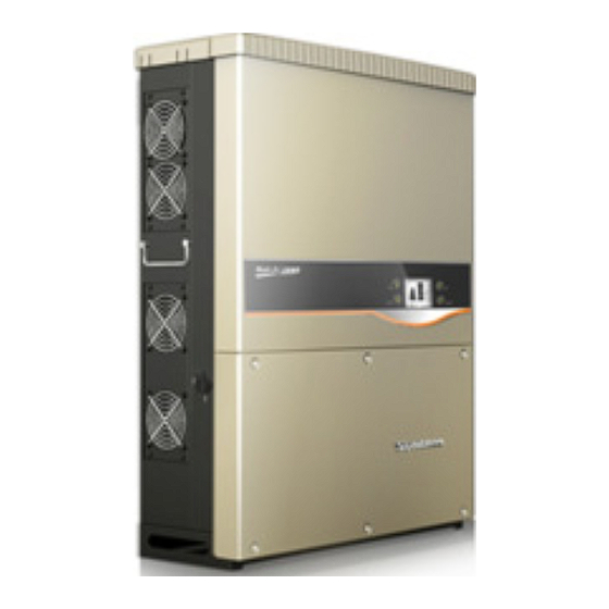
- Page 1 Quick User Manual SG30KTL-M PV Grid-Connected Inverter SG30KTL-MV2-QUEN-Ver22-201503 Version: 2.2...
- Page 3 No part of this document may be reproduced in any form or by any means without the prior written permission of Sungrow Power Supply Co., Ltd. Trademarks and other Sungrow trademarks used in this manual are owned by Sungrow Power Supply Co., Ltd. All other trademarks or registered trademarks mentioned in this document owned...
- Page 4 This quick user manual shall be used in accompany with the attached CD. SG30KTL-M will be referred to as inverter hereinafter unless otherwise specified. To prevent personal injury or material damage, the inverter must only be installed, operated, maintained and serviced by qualified personnel: They must be trained specially;...
-
Page 5: Table Of Contents
Contents 1 Important Safety Instructions ..........1 Symbols Explanation .................... 1 Symbols on the Inverter Body ................2 Important Safety Instructions ................2 2 Product Introduction ............... 6 Intended Usage ...................... 6 ... - Page 6 6 Technical Data ................ 26 Technical Data ..................... 26...
-
Page 7: 1 Important Safety Instructions
1 Important Safety Instructions 1.1 Symbols Explanation Important instructions contained in this manual should be followed during installation, operation and maintenance of the inverter. And they will be highlighted by the following symbols. DANGER indicates a hazard with a high level of risk which, if not avoided, will result in death or serious injury. -
Page 8: Symbols On The Inverter Body
1 Important Safety Instructions Quick User Manual 1.2 Symbols on the Inverter Body This symbol indicates that you should wait at least 10 minutes after disconnecting the inverter from the utility grid and from the PV input before touching any inner live parts. Hot surface! In order to reduce the risk of burns, do not touch the hot surface when the device is running. - Page 9 Quick User Manual 1 Important Safety Instructions Prior to installing the inverter onto the wall, it is crucial to make certain that the inverter is not electrically connected. System performance loss due to bad ventilation! The equipment requires good quality ventilation during operation. It is essential to keep the unit upright and nothing covering the heat sink in order to ensure that the equipment interior is well cooled down.
- Page 10 1 Important Safety Instructions Quick User Manual There is a risk of inverter damage or personal injury! Do not disconnect DC connectors while the inverter is under AC load! First de-energize the equipment from dual power sources and then verify that there is no voltage present.
- Page 11 Quick User Manual 1 Important Safety Instructions Servicing of the device in accordance with the manual should never be undertaken in the absence of proper tools, test equipment or more recent revision of the manual which is clearly and thoroughly understood.
-
Page 12: 2 Product Introduction
2 Product Introduction 2.1 Intended Usage SG30KTL-M, 3-phase without transformer string inverter, is a crucial unit between the PV strings and utility grid in the PV power system. The inverter CANNOT be connected to the PV modules, the positive or negative terminal of which needs to be grounded. -
Page 13: Principle Description
Quick User Manual 2 Product Introduction 2.2 Principle Description PV strings input voltage is transmitted to DC BUS via Boost circuit. The inverter is equipped with MPPTs for two DC inputs to ensure that the maximum power can be utilized even in different PV modules installation conditions. Inversion circuit converts DC power into AC power, which will be fed into the utility grid via five core terminals. -
Page 14: Unpacking And Detecting
Unpack the carton and take out all the accessories. Inspect the inverter for visible damages and check the completeness of the delivery contents according to the inner packing list. Contact your supplier if any of the contents is missing. SG30KTL-M is unavailable if any damage is detected. Fig. 2-3 Delivery Contents... - Page 15 Quick User Manual 2 Product Introduction Item Name Description Inverter unit Backplate It is used for mounting inverter onto the wall. Inverter cap It is for inverter’s better weather-proof function. Documents include quality certificate, packing list, product Documents test report,CD and quick user manual. Expansion Six units.
-
Page 16: 3 Mounting The Inverter
3 Mounting the Inverter 3.1 Select an optimal installation position The inverter must be mounted on a firm wall or metal frame. Mount the inverter at an appropriate site without flammable material and flammable gas nearby. Install the inverter vertically at eye level or tilted backwards by max. - Page 17 Quick User Manual 3 Mounting the Inverter Avoid exposing the inverter to the sunlight or rain or snow directly! Take enough space for convection into consideration during installing multiple inverters. It is suggested that position the multiple inverters in a staggered way if necessary.
-
Page 18: Installation
3 Mounting the Inverter Quick User Manual 3.2 Installation Move the inverter to the installation site with the help of another person or Step 1 the lifting device by means of the handles. Always remember the weight of the inverters! Grasp the equipment by both hands by means of handles. -
Page 19: 4 Electrical Connection
4 Electrical Connection Death hazards due to high voltage existing inside the inverter! Make sure that all the DC and AC cables to the inverter are not live before you start the electrical work. Do not turn on the AC side or DC side circuit breaker until all inverter electrical connections have completed. -
Page 20: Ac Connection
4 Electrical Connection Quick User Manual 4.2 AC Connection AC Side Circuit Breaker An independent three or four-pole circuit breaker (minimum size value 63A) for each inverter must be installed at the output side to ensure that the inverter can be securely disconnected. -
Page 21: Dc Connection
Quick User Manual 4 Electrical Connection 4.3 DC Connection 4.3.1 PV mode configuration The two PV inputs can be configured in independent mode or parallel mode. Refer to the user manual for an appropriate mode selection. PV configuration mode can be performed by a switch on the configuration circuit board. -
Page 22: Dc Cable Connection Procedures
4 Electrical Connection Quick User Manual 4.3.2 DC Cable Connection Procedures Make sure that all the DC and AC cables to the inverter are not live before you start the electrical work. Neither the DC positive pole nor the DC negative pole of the PV string is permitted to be grounded. -
Page 23: Second Protective Earth Terminal
Quick User Manual 4 Electrical Connection • Check the positive and negative polarity of the PV cells. After confirmation, you can insert the DC connectors into the input terminals on the bottom of the inverter. • For the same MPPT, reverse connection of a single string is prohibited. A permanent failure of the system or inverter may follow if otherwise. -
Page 24: Second Pe Terminals
4 Electrical Connection Quick User Manual 4.4.1 Second PE Terminals There is a second PE terminal on one side of the inverter. You may choose to connect PE connection. 4.4.2 Second PE Connection Item Description Remark Screw M4×12mm Lock washer Washer Cable socket Yellow-green cable... -
Page 25: Communication System
Quick User Manual 4 Electrical Connection Fig. 4-1 Communication Configuration 4.5.1 Communication System Where there is more than one inverter, all inverters can be connected to data logging device in daisy chain. The first and last inverters in the chain must be terminated with a resistor of 120Ω. - Page 26 4 Electrical Connection Quick User Manual SolarInfo logger and RS485-232 converter are optional parts and can be ordered from Sungrow. RJ45 Connection Lead Network cable through communication cable gland to the Step 1 configuration circuit board. Use the Ethernet crimper to crimp the cables and connect cables to RJ45 Step 2 plug according to TIA/EIA 568B.
-
Page 27: 5 Commissioning
Step 2 Suppose there are sufficient sunlight and enough DC power. PV arrays initialize and supply DC power to inverter. The LCD display is activated to check the validity first. If there is a defect on the display, contact Sungrow. - Page 28 5 Commissioning Quick User Manual Press to choose country code. Confirm the Step 3 settings by Pressing ENTER Select the country code according to the Step 4 inverter’s installation country. Each country code represents corresponding local protective parameters that have been preset before delivery.
- Page 29 Quick User Manual 5 Commissioning If country selected is not the three mentioned above, a Grid codes page as shown in the right will appear. Press to select. Confirm the selection by Pressing ENTER. When choose MV, Press ENTER to enter the LVRT function selection, Press to switch on or off the LVRT function and Press...
- Page 30 5 Commissioning Quick User Manual Configure time according to the local Step 10 time. Time setting is very important, which directly affects data logging. Press to move cursor and Press to scroll up time value. Confirm the settings by Pressing ENTER After configuring all parameters, there Step 11...
- Page 31 Quick User Manual 5 Commissioning Inverter will enter into startup process. Step 12 Observe status of LED indicators and the LCD main screen. If inverter‘s commissioning succeeds, the “RUN” indicator will be lit and “RUN” will be displayed on the “State” area. If inverter’s commissioning fails, the “FAULT”...
- Page 32 6 Technical Data 6.1 Technical Data Parameters SG30KTL-M Input Side Data Max. PV input power 30800W Max. PV input voltage 1000V Startup voltage 300V Nominal input voltage 620V MPP voltage range 280…950V MPP voltage range for nominal power 480...800V No. of MPPT(s) Max.
- Page 33 Parameters SG30KTL-M >0.99 default value at nominal power Power factor (adj. 0.8 overexcited...0.8 underexcited) Protection Anti-islanding protection LVRT AC short circuit protection Leakage current protection DC switch Integrated DC fuse Integrated Overvoltage protection Type II DC SPD System data Max. efficiency 98.3%...
- Page 34 Sungrow Power Supply Co., Ltd. Add: No.1699 Xiyou Rd.,New & High Technology Industrial Development Zone, 230088,Hefei, P. R. China. Post Zip: 230088 Web: www.sungrowpower.com Tel: +86 551 6532 7834/6532 7845 E-mail: info@sungrow.cn Fax: +86 551 6532 7856 Specifications are subject to changes without advance notice.
Need help?
Do you have a question about the SG30KTL-M and is the answer not in the manual?
Questions and answers