Sungrow SG30CX User Manual
Pv grid-connected inverter
Hide thumbs
Also See for SG30CX:
- User manual (129 pages) ,
- Quick manual (21 pages) ,
- User manual (103 pages)

Related Manuals for Sungrow SG30CX


Summary of Contents for Sungrow SG30CX
- Page 1 PV Grid-Connected Inverter User Manual SG30_33_40_50CX SG30_33_40_ 50CXPV Grid-Connected InverterUser ManualSG30_33_40_ 50CX-UEN-Ver20-202203 SG30_33_40_50CX-UEN-Ver20-202203...
-
Page 3: All Rights Reserved
Software Licenses • It is prohibited to use data contained in firmware or software developed by SUNGROW, in part or in full, for commercial purposes by any means. • It is prohibited to perform reverse engineering, cracking, or any other operations that... -
Page 4: About This Manual
Please read this manual carefully before using the product and keep it properly at a place for easy access. All contents, pictures, marks, and symbols in this manual are owned by SUNGROW. No part of this document may be reprinted by the non-internal staff of SUNGROW without written authorization. - Page 5 Symbols This manual contains important safety instructions, which are highlighted with the following symbols, to ensure personal and property safety during usage, or to help optimize the prod- uct performance in an efficient way. Please carefully understand the meaning of these warning symbols to better use the manual. Indicates high-risk potential hazards that, if not avoided, may lead to death or seri- ous injury.
-
Page 7: Table Of Contents
Contents All Rights Reserved .....................I About This Manual......................II 1 Safety .........................1 1.1 Unpacking and Inspection ................1 1.2 Installation Safety ...................1 1.3 Electrical Connection Safety................2 1.4 Operation Safety ....................3 1.5 Maintenance Safety ..................4 1.6 Disposal Safety ....................4 2 Product Description ..................5 2.1 System Introduction ..................5 2.2 Product Introduction..................6 2.3 Symbols on the Product ..................8... - Page 8 4.5 Installing the mounting-bracket ..............23 4.5.1 PV Bracket-Mounted Installation ............23 4.5.2 Wall-Mounted Installation..............24 4.6 Installing the Inverter..................25 5 Electrical Connection ..................27 5.1 Safety Instructions ..................27 5.2 Terminal Description ..................28 5.3 Electrical Connection Overview ..............29 5.4 Crimp OT / DT terminal .................31 5.5 External Grounding Connection ..............32 5.5.1 External Grounding Requirements............32 5.5.2 Connection Procedure.................32...
- Page 9 6.2 Commissioning Procedure ................55 7 iSolarCloud App ....................56 7.1 Brief Introduction ..................56 7.2 Installing the App ..................56 7.3 Function Overview..................57 7.4 Login ......................57 7.4.1 Requirements ..................57 7.4.2 Login Procedure .................57 7.5 Home page ....................61 7.6 Run Information....................63 7.7 Records .......................65 7.8 More......................67 7.8.1 System Parameters................67 7.8.2 Operation Parameters .................68...
-
Page 11: Safety
Perform operations considering ac- tual onsite conditions. • SUNGROW shall not be held liable for any damage caused by violation of gen- eral safety operation requirements, general safety standards, or any safety in- struction in this manual. -
Page 12: Electrical Connection Safety
1 Safety User Manual Improper installation may cause personal injury! • If the product supports hoisting transport and is hoisted by hoisting tools, no one is allowed to stay under the product. • When moving the product, be aware of the product weight and keep the balance to prevent it from tilting or falling. -
Page 13: Operation Safety
User Manual 1 Safety Damage to the product caused by incorrect wiring is not covered by the warranty. • Electrical connection must be performed by professionals. • All cables used in the PV generation system must be firmly attached, properly insulated, and adequately dimensioned. -
Page 14: Maintenance Safety
To avoid the risk of electric shock, do not perform any other maintenance opera- tions beyond this manual. If necessary, contact SUNGROW for maintenance. Oth- erwise, the losses caused is not covered by the warranty. Disposal Safety Please scrap the inverter in accordance with relevant local regulations and stand- ards to avoid property losses or casualties. -
Page 15: Product Description
Description Item Note Monocrystalline silicon, polycrystalline silicon and thin-film PV strings without grounding. SG30CX, SG33CX, SG40CX, SG50CX. Inverter Grid connection Includes devices such as AC circuit breaker, SPD, metering cabinet device. Boost the low voltage from the inverter to grid-compatible me- Transformer dium voltage. -
Page 16: Product Introduction
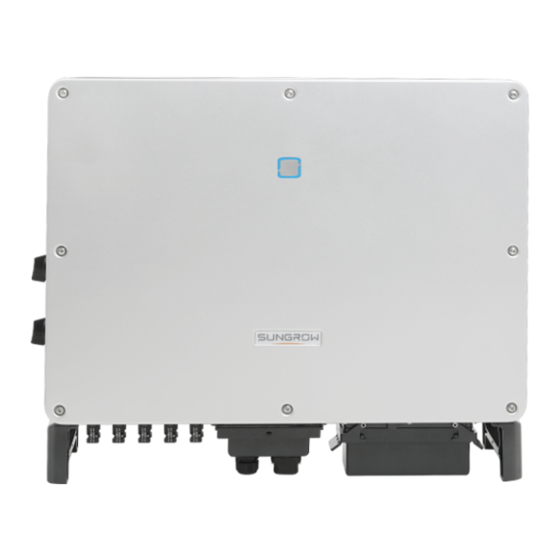
User Manual Product Introduction Model Description The model description is as follows(Take SG30CX as an example) : Appearance The following figure shows the appearance of the inverter. The image shown here is for reference only. The actual product received may differ. - Page 17 User Manual 2 Product Description figure 2-2 Inverter Appearance Description Name To indicate the current working state of the inverter. LED indicator Mounting ears To hang the inverter onto the mounting-bracket. To move the inverter. Side handles Warning symbols, nameplate, and QR code. Labels Additional ground- Use to ground the inverter.
-
Page 18: Symbols On The Product
2 Product Description User Manual Type Dimensions (W*H*D) Weight SG30CX 50 kg 702×595×310 mm SG33CX 58 kg SG40CX 782×645×310 mm 62 kg SG50CX Symbols on the Product Symbol Explanation Do not dispose of the inverter together with household waste. TÜV mark of conformity. -
Page 19: Dc Switch
DC Switch The DC switch is used to disconnect the DC current safely whenever necessary. The SG30CX and SG33CX is equipped with one DC switch to control the connection and disconnection of all DC terminals. The SG40CX and SG50CX are equipped with two DC switches separately controlling a... -
Page 20: Circuit Diagram
2 Product Description User Manual * The image shown here is for reference only. The actual product received may differ. Turn the DC switches to the ON position before restarting the inverter. Circuit Diagram The following figure shows the main circuit of the inverter. figure 2-4 Circuit Diagram •... -
Page 21: Function Description
After communication connection is established, users can view inverter information or set in- verter parameters through the iSolarCloud. It is recommended to use the communication module from SUNGROW. Using a device from other companies may lead to communication failure or other unex- pected damage. - Page 22 2 Product Description User Manual • For negative voltage scheme, after the PID is enabled, the voltage to ground of all PV strings is lower than 0, and therefore the PV string-to-ground voltage is a negative value. • Before enabling the PID recovery function, make sure the voltage polarity of the PV modules to ground meets requirement.
-
Page 23: Unpacking And Storage
• Check the inner contents for damage after unpacking. Contact SUNGROW or the transport company in case of any damage or incompleteness, and provide photos to facilitate services. Do not dispose of the original packing case. It is recommended to store the device in the original packing case when the product is decommissioned. - Page 24 3 Unpacking and Storage User Manual • Do not place the inverter in places with items that may affect or damage the inverter. • Store the inverter in a clean and dry place to prevent dust and water vapor from eroding. •...
-
Page 25: Mechanical Mounting
Mechanical Mounting Respect all local standards and requirements during mechanical installation. Safety during Mounting Make sure there is no electrical connection before installation. Before drilling, avoid the water and electricity wiring in the wall. Poor installation environment will affect system performance! •... -
Page 26: Environment Requirements
The ambient temperature and relative humidity must meet the following requirements. • Please consult SUNGROW before installing inverters outdoors in salt stress areas. Salt stress areas mainly refer to coastal areas that are within 500 meters from the coast. The deposition of salt fog varies largely with nearby seawater characteristics, sea wind, pre- cipitation, relative humidity, terrain, and forest coverage. -
Page 27: Angle Requirements
Install the inverter vertically or at the maximum allowable rear tilt angle. Do not install the in- verter horizontally, forward, excessively backward, sideways, or upside down. Please consult SUNGROW before tilting backwards the inverter and install it in floating power plants. - Page 28 4 Mechanical Mounting User Manual * In case this distance is less than the distance in the diagram, move the inverter from the mounting-bracket or wall before maintaining fans. The distance between the bottom of the inverter and the ground surface is deter- mined according to the bending radius of the AC cable used and the installation environment.
-
Page 29: Installation Tools
User Manual 4 Mechanical Mounting In case of back-to-back installation, reserve specific clearance between the two inverters. Install the inverter at an appropriate height for ease of viewing LED indicator and operating switch(es). Installation Tools Installation tools include but are not limited to the following recommended ones. If necessary, use other auxiliary tools on site. -
Page 30: Moving The Inverter
4 Mechanical Mounting User Manual Hammer drill Pliers Marker Level (φ12, φ14) Rubber mallet Socket wrench set Wrench Wrist strap (16mm) (13 mm, 16 mm) Wire cutter Wire stripper Hydraulic plier Heat gun MC4 terminal MC4 terminal Multimeter RJ45 crimping tool crimping pliers wrench ≥... -
Page 31: Manual Transport
User Manual 4 Mechanical Mounting • Always be aware of the weight of the inverter. • Lift the inverter using the handles positioned on both sides of the inverter. • Move the inverter by one or two people or by using a proper transport tool. •... - Page 32 4 Mechanical Mounting User Manual step 2 Lead the sling through the two lifting rings and fasten the tie-down strap. step 3 Hoist the inverter, and stop to check for safety when the inverter is 100mm above the ground. Continue hoisting the device to the destination after ensuring the safety. step 4 Remove the lifting rings and reassemble the sealing screws released in Step 1.
-
Page 33: Installing The Mounting-Bracket
User Manual 4 Mechanical Mounting The lifting rings and the sling are not within the delivery scope. - - End Installing the mounting-bracket Inverter is installed on the wall and bracket by means of mounting bracket. The expansion plug set shown below is recommended for the installation. figure 4-1 Dimensions of mounting-bracket 4.5.1 PV Bracket-Mounted Installation step 1 Assemble the mounting-bracket by using the connecting bar. -
Page 34: Wall-Mounted Installation
4 Mechanical Mounting User Manual Components Description Mounting-bracket – Full threaded bolt M10*45 – Metal bracket – Flat washer Spring washer – – Hex nuts - - End 4.5.2 Wall-Mounted Installation step 1 Assemble the mounting-bracket by using the connecting bar. step 2 Level the assembled mounting-bracket by using the level, and mark the positions for drilling holes on the installation site. -
Page 35: Installing The Inverter
User Manual 4 Mechanical Mounting step 4 Fix the mounting-bracket with the expansion bolts. Components Description – Wall Fastening the bolt in the sequence of nut, spring wash- Expansion bolt er, slat washer Mounting-bracket – - - End Installing the Inverter step 1 Take out the inverter from the packing case. - Page 36 4 Mechanical Mounting User Manual - - End...
-
Page 37: Electrical Connection
Electrical Connection Safety Instructions The PV string will generate lethal high voltage when exposed to sunlight. • Operators must wear proper personal protective equipment during electrical connections. • Must ensure that cables are voltage-free with a measuring instrument before touching DC cables. •... -
Page 38: Terminal Description
5 Electrical Connection User Manual • All vacant terminals must be covered with waterproof covers to prevent affect- ing the protection rating. • When the wiring is completed, seal the gap of cable inlet and outlet holes with fireproof / waterproof materials such as fireproof mud to prevent foreign matter or moisture from entering and affecting the long-term normal operation of the inverter. -
Page 39: Electrical Connection Overview
User Manual 5 Electrical Connection Item Terminal Mark Note MC4 PV connector SG30CX, SG33CX: 6 pairs of terminals PV terminals + / - SG40CX: 8 pairs of terminals SG50CX: 10 pairs of terminals For RS485 communication wiring. COM1 COM2 For Communication module connection. - Page 40 Outdoor single- The same as that of the PE wire in the AC grounding core copper wire cable cable cable L1,L2,L3,N wire (SG30CX, SG33CX): 16 ~ 70 L1,L2,L3,N wire (SG40CX): Outdoor multicore 25 ~ 70 AC cable copper or alumi-...
-
Page 41: Crimp Ot / Dt Terminal
User Manual 5 Electrical Connection Crimp OT / DT terminal Crimp OT / DT terminal 1. Heat shrink tubing 2. OT DT terminal 3. Hydraulic pliers 4. Heat gun Aluminium Cable Requirements If an aluminium cable is selected, use a copper to aluminium adapter terminal to avoid direct contact between the copper bar and the aluminium cable. -
Page 42: External Grounding Connection
The ground connection of this additional grounding terminal cannot replace the connection of the PE terminal of the AC cable. Make sure those terminals are both grounded reliably. SUNGROW shall not be held liable for any damage caused by the violation. -
Page 43: Ac Cable Connection
AC Circuit Breaker An independent circuit breaker or fuse should be installed on the output side of the inverter to ensure safe disconnection from the grid. Recommended rated voltage Inverter Recommended rated current SG30CX SG33CX 400V SG40CX SG50CX 100A... - Page 44 500 mA Multiple Inverters in Parallel Connection If multiple inverters are connected in parallel to the grid, ensure that the total number of par- allel inverters does not exceed 30. Otherwise, please contact SUNGROW for technical scheme. MV Transformer The MV transformer used together with the inverter should meet the following requirements: •...
-
Page 45: Requirements For Ot/Dt Terminal
The apparent power of the inverter should never exceed the power of the transformer. The maximum AC current of all inverters connected in parallel must be taken into ac- count. If more than 30 inverters are connected to the grid, contact SUNGROW. •... - Page 46 5 Electrical Connection User Manual Outer diameter D(mm) Seals 20~25 a+b+c+d 25~30 a+b+c 30~40 40~50 step 3 Strip the protection layer and insulation layer by specific length, as described in the figure below. step 4 Make the cable and crimp OT/DT terminal,refer to "...
- Page 47 User Manual 5 Electrical Connection Ensure that the depth L of the socket used is not less than 18mm. step 7 Secure the junction box, fasten the buckle, and secure it with supplied M4×10 screw. step 8 Gently pull the cable backwards to ensure firm connection, and fasten the swivel nut clockwise.
-
Page 48: Dc Cable Connection
The damage caused by this is not covered by the warranty. • Electric arc or contactor over-temperature may occur if the PV connectors are not firmly in place, and SUNGROW shall not be held liable for any damage caused. •... -
Page 49: Pv Input Configuration
5-3 PV Input Configuratinon Prior to connecting the inverter to PV inputs, the specifications in the following table should be met: Open-circuit Voltage Max. Current for Input Type Limit Connector SG30CX 1100 V 30 A SG33CX 1100 V 30 A... -
Page 50: Assembling The Pv Connectors
Use MC4-Evo2 DC terminals if the maximum input voltage is greater than 1,000 V. To purchase the MC4-Evo2 DC terminals, contact SUNGROW. • Select appropriate DC terminals as required above. Otherwise, SUNGROW shall be held no liability for the damage caused. To ensure IP66 protection, use only the supplied connector. -
Page 51: Installing The Pv Connector
User Manual 5 Electrical Connection step 3 Lead the cable through cable gland, and insert the crimp contact into the insulator until it snaps into place. Gently pull the cable backward to ensure firm connection. Tighten the ca- ble gland and the insulator (torque 2.5 N.m to 3 N.m). step 4 Check for polarity correctness. -
Page 52: Communication Junction Box
5 Electrical Connection User Manual step 4 Follow the foregoing steps to connect PV connectors of other PV strings. step 5 Seal any unused PV terminal with a terminal cap. - - End Communication Junction Box Remove the Junction Box Pull out the pin and keep it properly, remove the junction box. -
Page 53: Communication Wiring Board
User Manual 5 Electrical Connection During installation, firmly press the junction box to ensure that the pin can be in- serted successfully. Never hit the pin with a heavy object, such a hammer. Otherwise, it will be irrecov- erably damaged. Communication Wiring Board The communication board of the inverter includes two layers. -
Page 54: Rs485 Communication System
5 Electrical Connection User Manual The RS485-1 crimp and the RJ45 interface can be applied to applications where multiple in- verters communicate in a daisy-chain form. A 120Ω resistor can be connected in parallel between RS485-1 A/B pins by configuring the dip switch. - Page 55 User Manual 5 Electrical Connection figure 5-5 Multi-inverter Connection When more than 15 inverters are connected to the same daisy chain, in order to ensure the communication quality, the Logger at the first end of the daisy chain needs to be equipped with a terminal resistor of 120Ω, the inverter at the last end needs to be equipped with a RS485-dip switch (SW1), and the shielding layer of the communication cable should be sin- gle-point grounded.
-
Page 56: Connection Procedure(Terminal Block)
5 Electrical Connection User Manual 5.10.3 Connection Procedure(Terminal Block) RS485 communication cables should be shielded twisted pair cables or shielded twisted pair Ethernet cables. There are three communication terminals, and the silkscreen marks are COM1/ COM2/COM3. Please choose according to the actual situation. step 1 Remove the communication junction box, see"... -
Page 57: Connection Procedure (Rj45 Ethernet Port)
User Manual 5 Electrical Connection step 5 Insert the terminal base into the corresponding terminal. table 5-3 Terminal definition Definition RS485 A IN, RS485A differential signal+ RS485 A OUT, RS485A differential signal+ RS485 B IN, RS485B differential signal- RS485 B OUT, RS485B differential signal- step 6 If other wiring operations need to be performed on the communication board, finish the wir- ing operations before performing the following steps. - Page 58 5 Electrical Connection User Manual Outer Diameter D(mm) Seal 4.5 ~ 6 6 ~ 12 a + b 12 ~ 18 step 3 Strip the insulation layer of the Ethernet cable with a wire stripper, and insert the signal wires to the RJ45 connector(Pin 3 and Pin 6 are for communication connection).
-
Page 59: Dry Contact Connection
User Manual 5 Electrical Connection 5.11 Dry Contact Connection Dry contact cables require a cross section of 1 mm to 1.5 mm The connection procedure of the dry contact is the same as that of the RS485 ter- minal block. 5.11.1 Dry Contact Function The configuration circuit board is provided with fault output dry contact and emergency stop dry contact, as shown in the figure below. - Page 60 5 Electrical Connection User Manual figure 5-7 Normal open contact figure 5-8 Normal close contact Devices connected to the relay should comply with related requirements: AC-Side Requirements DC-Side Requirements Max. voltage: 250 Vac Max. voltage: 30Vdc Max. current: 5A Max. current: 5A DI terminal (emergency stop dry contact): the dry contact can be configured to be an emergency stop contact.
-
Page 61: Wiring Procedure
User Manual 5 Electrical Connection figure 5-9 Local stop contact figure 5-10 Daisy chain topology When wiring DI dry contacts, ensure that the maximum wiring distance meet the require- ments in "10.2 Wring Distance of DI Dry Contact". 5.11.2 Wiring Procedure Refer to the wiring of terminal block described in chapter"5.10.3 Connection Procedure(Ter- minal Block)"... -
Page 62: Connection Procedure
Asserted when the impedance between pins 5 and 6 is detected to be above 20kΩ Enable the DRM function through the iSolarCloud APP. If there are any problems, contact SUNGROW. The DRM function is only applicable to devices for Australia and New Zealand. 5.12.2 Connection Procedure step 1 Remove the communication junction box, see"... - Page 63 User Manual 5 Electrical Connection step 3 Loosen the swivel nut and select an appropriate seal according to cable outer diameter. Lead the cable through the swivel nut, and seal successively. Outer Diameter D Seal (mm) 4.5 ~ 6 6 ~ 12 a + b 12 ~ 18 step 4 Insert the RJ45 connector to the RJ45 jack.
-
Page 64: Communication Module Connection (Optional)
- - End 5.13 Communication Module Connection (optional) Connect the communication module produced by SUNGROW to the communication acces- sory port. After successful connection, information such as power generation and running state of the inverter can be viewed via the App on the phone. -
Page 65: Commissioning
Commissioning Inspection before Commissioning Check the following items before starting the inverter: • All equipment has been reliably installed. • DC switch(es) and AC circuit breaker are in the "OFF" position. • The ground cable is properly and reliably connected. •... -
Page 66: Isolarcloud App
iSolarCloud App Brief Introduction The iSolarCloud App can establish communication connection to the inverter via the Blue- tooth, thereby achieving near-end maintenance on the inverter. Users can use the App to view basic information, alarms, and events, set parameters, or download logs, etc. *In case the communication module Eye, WiFi or WiNet-S is available, the iSolarCloud App can also establish communication connection to the inverter via the mobile data or WiFi, thereby achieving remote maintenance on the inverter. -
Page 67: Function Overview
User Manual 7 iSolarCloud App Function Overview The App provides parameter viewing and setting functions, as shown in the following figure. figure 7-1 App function tree map Login 7.4.1 Requirements The following requirements should be met: • The AC or DC side of the inverter is powered-on. •... - Page 68 7 iSolarCloud App User Manual side of the inverter for Bluetooth connection. The connection is successfully established if the LED indicator blinks blue. figure 7-2 Bluetooth Connection step 3 Enter the identity verification screen after the Bluetooth connection is established.
- Page 69 To set inverter parameters related to grid protection and grid support, contact SUNGROW to obtain the advanced account and corresponding password. step 4 If the inverter is not initialized, you will enter the quick setting screen of initializing protection parameter.
- Page 70 In the Brazilian region, set the country code as "Brazil". Selecting "Brazil_230" or "Brazil_240" will cause setting failure. For SG30CX, set the grid code as EN50549 in the Ukraine region and apply man- ual settings for country code compliance. step 5 When the country is set to Australia, additionally set the applicable network service provider and then the grid type.Tap Power Company to select the correct power company.
-
Page 71: Home Page
User Manual 7 iSolarCloud App CitiPower & Powercor • ≤ 5 kVA for single-phase & 30 kVA for three-phase • > 30 kVA three-phase United Energy • UE-ST-2008.1: ≤ 10 kW for single- phase & 30 kW for three-phase • UE-ST-2008.2: >... - Page 72 7 iSolarCloud App User Manual figure 7-6 Home Page table 7-2 Home Page Description Designation Description System date and time of the inverter. Date and time Present operation state of the inverter. For details, refer to Inverter state "table 7-3 Description of Inverter State".
-
Page 73: Run Information
User Manual 7 iSolarCloud App table 7-3 Description of Inverter State Description State After being energized, the inverter tracks the PV arrays’ maximum power point (MPP) and converts the DC power into AC power. This is the nor- mal operation mode. Stop The inverter is stopped. - Page 74 7 iSolarCloud App User Manual table 7-5 Run Information Classifica- Description Parameter tion String n Voltage The input voltage of the n string String n current The input current of the n string Information Total On-grid Run- ning Time Daily On-grid Run- ning Time Negative Voltage to Inverter DC side negative to ground voltage value...
-
Page 75: Records
User Manual 7 iSolarCloud App Classifica- Description Parameter tion Phase C Current Records Tap Records on the navigation bar to enter the screen showing event records, as shown in the following figure. figure 7-7 Records Fault Alarm Record Tap Fault Alarm Record to enter the screen, as shown in the following figure. figure 7-8 Fault Alarm Record Click to select a time segment and view corresponding records. - Page 76 7 iSolarCloud App User Manual figure 7-9 Detailed Fault Alarm Information Yield Record Tap Yield Record to enter the screen showing daily power generation , as shown in the fol- lowing figure. figure 7-10 Power Curve The App displays power generation records in a variety of forms, including daily power gen- eration graph, monthly power generation histogram, annual power generation histogram and total power generation histogram.
-
Page 77: More
User Manual 7 iSolarCloud App Description Parameter Monthly energy Shows the power output every month in a year. histogram Annual energy Shows the power output every year. histogram Tap the time bar on the top of the screen to select a time segment and view the correspond- ing power curve. -
Page 78: Operation Parameters
7 iSolarCloud App User Manual figure 7-12 System Parameters * The image shown here is for reference only. Boot/Shutdown Tap Boot/Shutdown to send the boot/shutdown instruction to the inverter. For Australia and New Zealand, when the DRM state is DRM0, the "Boot" option will be prohibited. - Page 79 User Manual 7 iSolarCloud App figure 7-14 PID Setting table 7-7 PID Parameter Description Description Parameter Set enabling/disabling of the PID night recovery function. PID night PID Recovery recovery function operates between 22:00 pm and 5:00 am by default. If ISO impedance abnormality or PID function exception is de- tected during running of the PID function, the inverter reports a Clear PID alarm PID false alarm and reminds the user to take corresponding meas-...
-
Page 80: Power Regulation Parameters
7 iSolarCloud App User Manual figure 7-16 NS Protection(Passive Valid) 7.8.3 Power Regulation Parameters Active Power Regulation Tap Settings→Power Regulation Parameters→Active Power Regulation to enter the screen, as shown in the following figure. figure 7-17 Active Power Regulation table 7-8 Active Power Regulation Definition/Setting Range Parameter... - Page 81 User Manual 7 iSolarCloud App Definition/Setting Range Parameter Description Active power rising The rise rate of inverter active 1%/min~6000%/min gradient power per minute. Active power setting Switch for enabling/disabling Enable/Disable persistence the function of saving output limited power. Active power limit The switch for limiting output Enable/Disable power.
- Page 82 7 iSolarCloud App User Manual figure 7-18 Reactive Power Regulation table 7-9 Reactive Power Regulation Definition/Setting Range Parameter Description Reactive power genera- Switch for enabling/disabling Enable/Disable tion at night Q at night function. Reactive power ratio at Reactive power ratio set for -100%~0%/ night the Q at night function.
- Page 83 User Manual 7 iSolarCloud App Definition/Setting Range Parameter Description QP_P3 Output power at P3 on the Q 20.0%~100.0% (P) mode curve (in percentage) QP_K1 Power factor at P1 on the Q(P) Curve A/Curve mode curve C:0.800~1.000 Curve B: [-0.600~0.600]*Ac- tive Overload Rate/1000 QP_K2 Power factor at P2 on the Q(P) Curve A/Curve C:...
- Page 84 7 iSolarCloud App User Manual Definition/Setting Range Parameter Description QU_V2 Pre-set grid voltage U2 that is 80.0%~100.0% reactive according to the grid voltage. QU_Q2 Pre-set proportion of reactive [-60.0%-60.0%]* Overload power according to the grid Rate/1000 voltage U2. QU_V3 Pre-set grid voltage U3 that is 100.0%~120.0% reactive according to the grid voltage.
-
Page 85: Communication Parameters
User Manual 7 iSolarCloud App figure 7-19 Q(U) Curve figure 7-20 Q(P) Curve 7.8.4 Communication Parameters Tap Settings→Communication Parameters→Serial Port Parameters to enter the corre- sponding interface, as shown in the following figure. figure 7-21 Serial Port Parameters table 7-10 Serial Port Parameters Range Parameter Device Address... -
Page 86: Firmware Update
7 iSolarCloud App User Manual figure 7-22 MPLC Parameters table 7-11 MPLC Parameters Range Parameter Band Num Band1, Band2 Array ID 1–255 Winding ID 1–10 7.8.5 Firmware Update To avoid download failure due to poor on-site network signal, it is recommended to download the firmware package to the mobile device in advance. -
Page 87: Password Changing
User Manual 7 iSolarCloud App step 8 Tap the upgrade package file, a prompt box will pop up asking you to upgrade the firmware with the file, tap CONFIRM to perform the firmware upgrade. step 9 Wait for the file to be uploaded. When the upgrade is finished, the interface will inform you of the upgrade completion. -
Page 88: System Decommissioning
System Decommissioning Disconnecting the Inverter Danger of burns! Even if the inverter is shut down, it may still be hot and cause burns. Wear protec- tive gloves before operating the inverter after it cools down. For maintenance or other service work, the inverter must be switched off. Proceed as follows to disconnect the inverter from the AC and DC power sources. -
Page 89: Disposal Of The Inverter
User Manual 8 System Decommissioning step 2 Refer to"4 Mechanical Mounting", to dismantle the inverter in reverse steps. step 3 If necessary, remove the wall-mounting bracket from the wall. step 4 If the inverter will be used again in the future, please refer to "3.2 Inverter Storage"... -
Page 90: Troubleshooting And Maintenance
App or the LCD. Modify the overvoltage protection values with the con- sent of the local electric power operator. 3. Contact Sungrow Customer Service if the pre- ceding causes are ruled out and the fault persists. Generally, the inverter will be reconnected to the grid after the grid returns to normal. - Page 91 2. Check whether the protection parameters are appropriately set via the App or the LCD. 3. Contact Sungrow Customer Service if the pre- ceding causes are ruled out and the fault persists. Generally, the inverter will be reconnected to the grid after the grid returns to normal.
- Page 92 App or the LCD. 3. Contact Sungrow Customer Service if the pre- ceding causes are ruled out and the fault persists. 1. Check whether the corresponding string is of reverse polarity.
- Page 93 3. Check if the DC fuse is damaged. If so, replace Alarm the fuse. 4. Contact Sungrow Customer Service if the pre- ceding causes are ruled out and the alarm persists. *The code 548 to code 563 are corresponding to string 1 to string 16 respectively.
- Page 94 3. If the cable is normal and the fault occurs on rainy days, check it again when the weather turns fine. 4. Contact Sungrow Customer Service if the pre- ceding causes are ruled out and the fault persists. 1. Check whether the AC cable is correctly connected.
- Page 95 2. Reconnect the communication cable of the cation Abnormal meter. Alarm 3. Contact Sungrow Customer Service if the pre- ceding causes are ruled out and the alarm persists. 1. Check whether the output port is connected to actual grid. Disconnect it from the grid if so.
- Page 96 0.5 A. MPPT Reverse 264-283 2. Contact Sungrow Customer Service if the pre- Connection ceding causes are ruled out and the fault persists. *The code 264 to code 279 are corresponding to string 1 to string 20 respectively.
- Page 97 3. Do not reinsert the faulty strings before the grounding fault is cleared; 4. If the fault is not caused by the foregoing rea- sons and still exists, contact Sungrow Customer Service. 1. It is prohibited to disconnect the DC switch when the DC current is greater than 0.5 A when...
-
Page 98: Maintenance
To avoid the risk of electric shock, do not perform any other maintenance opera- tions beyond this manual. If necessary, contact SUNGROW for maintenance. Oth- erwise, the losses caused is not covered by the warranty. -
Page 99: Routine Maintenance
User Manual 9 Troubleshooting and Maintenance 9.2.2 Routine Maintenance Item Method Period Check the temperature and dust of the inverter. Clean the inverter enclo- Six months to a year (de- sure if necessary. System clean pend on the dust contents Check if the air inlet and outlet are in air.) normal. - Page 100 9 Troubleshooting and Maintenance User Manual Fans inside the inverter are used to cool the inverter during operation. If the fans do not op- erate normally, the inverter may not be cooled down and inverter efficiency may decrease. Therefore, it is necessary to clean dirty fans and replace the broken fans in a timeiy manner. The operation procedure is as follows: step 1 Stop the inverter (see 8.1 Disconnecting the Inverter).
- Page 101 User Manual 9 Troubleshooting and Maintenance - - End...
-
Page 102: Appendix
10 Appendix 10.1 Technical Data SG30CX SG30CX Parameters SG33CX Input (DC) Recommended max. PV in- 45kW put power 1100V Max. PV input voltage Min. PV input voltage / 200V / 250V Start-up input voltage Nominal PV input voltage 585V MPP voltage range 200 –... - Page 103 User Manual 10 Appendix SG30CX SG30CX Parameters SG33CX Power factor at nominal > 0.99 / 0.8 leading – 0.8 lagging power / Adjustable power factor Feed-in phases / AC connection Efficiency Max. efficiency / European 98.6% / 98.3% efficiency Protection...
- Page 104 10 Appendix User Manual SG30CX SG30CX Parameters SG33CX 4000 m (> 3000 m derating) Max. operating altitude LED, Bluetooth + App Display RS485 / WLAN / RS485 / Option- RS485 / Optional: Optional: al: WLAN , WLAN, Ethernet Communication Ethernet Ethernet MC4 (Max.
- Page 105 User Manual 10 Appendix SG50CX SG50CX SG40CX Parameters 40 kVA @45 ℃, 50 kVA @45 ℃, 400Vac / 44 kVA 400Vac / 55kVA @ @ 40 ℃, 40 ℃, 400Vac 400Vac 40 50kVA AC output power 50KVA@50℃, KVA@50℃, 415Vac / 55kVA @ 415Vac / 44 45 ℃,415Vac KVA@45℃,...
-
Page 106: Wring Distance Of Di Dry Contact
10 Appendix User Manual SG50CX SG50CX SG40CX Parameters Arc fault circuit interrupter Opt. Opt. (AFCI) DC Type II (Type DC Type II / AC DC Type II (Type I + I + II Opt.) / AC Surge protection Type II II Opt.) / AC Type II Type II General Data... - Page 107 User Manual 10 Appendix refers to the cable length in one direction between the DI dry contact terminal of the k verter and the corresponding terminal of the (k-1) inverter. table 10-1 Correspondence between number of inverters and maximum wiring distance Maximum wiring distance(unit:m) Number of inverter...
-
Page 108: Quality Assurance
• The customer shall give SUNGROW a reasonable period to repair the faulty device. Exclusion of Liability In the following circumstances, SUNGROW has the right to refuse to honor the quality guarantee: • The free warranty period for the whole machine/components has expired. - Page 109 User Manual 10 Appendix We need the following information to provide you the best assistance: • Model of the device • Serial number of the device • Fault code/name • Brief description of the problem For detailed contact information, please visit: https://en.sungrowpower.com/contactUS.
Need help?
Do you have a question about the SG30CX and is the answer not in the manual?
Questions and answers