Table of Contents
Advertisement
Quick Links
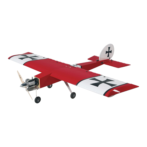
SPECIFICATIONS
Wingspan: 96.5 in [2451mm]
Length: 85 in [2159 mm]
Weight: 18 – 21 lb [8165 – 9525 g]
Radio: 5 + channel radio
WARRANTY
Great Planes
®
Model Manufacturing Co. guarantees this kit to
be free from defects in both material and workmanship at the
date of purchase. This warranty does not cover any component
parts damaged by use or modification. In no case shall Great
Planes' liability exceed the original cost of the purchased kit.
Further, Great Planes reserves the right to change or modify this
warranty without notice.
In that Great Planes has no control over the final assembly or
material used for final assembly, no liability shall be assumed nor
READ THROUGH THIS MANUAL BEFORE STARTING CONSTRUCTION. IT CONTAINS IMPORTANT
INSTRUCTIONS AND WARNINGS CONCERNING THE ASSEMBLY AND USE OF THIS MODEL.
© 2017 Great Planes Model Mfg. A subsidiary of Hobbico,
XL 55-61cc/EP ARF
XL 55-61cc/EP ARF
XL 55-61cc/EP ARF
XL 55-61cc /EP ARF
Wing Area: 2029 in
Wing Loading: 20 – 24 oz/ft
[61– 73 g /dm
Battery: 12 S 5000mAh
®
Inc.
INSTRUCTION MANUAL
2
2
[131 dm
]
Engine: 3.4 – 3.7 cu.in. [ 55 – 61cc] spark ignition gas
Motor: Great Planes RimFire .65
2
(80-85-160) Outrunner Brushless
2
]
ESC: 160A High Voltage
accepted for any damage resulting from the use by the user of
the final user-assembled product. By the act of using the
user-assembled product, the user accepts all resulting liability.
If the buyer is not prepared to accept the liability associated
with the use of this product, the buyer is advised to return
this kit immediately in new and unused condition to the
place of purchase.
To make a warranty claim, go to: greatplanes.com/support
GPMA1225
Advertisement
Table of Contents

Related Manuals for GREAT PLANES GIANT BIG STIK XL 55-61cc/EP ARF


Summary of Contents for GREAT PLANES GIANT BIG STIK XL 55-61cc/EP ARF
- Page 1 In that Great Planes has no control over the final assembly or To make a warranty claim, go to: greatplanes.com/support material used for final assembly, no liability shall be assumed nor READ THROUGH THIS MANUAL BEFORE STARTING CONSTRUCTION.
-
Page 2: Table Of Contents
For the latest technical updates or manual corrections to FAA rules. Please contact your local authorities to fi nd out the 55cc Big Stik ARF, visit the Great Planes web site at the latest rules and regulations. As of this printing, the FAA www.greatplanes.com. -
Page 3: Decisions You Must Make
(FPWP5506) area whose membership includes experienced pilots. Great Planes Standoff Brushless Motor Mount XX Large 6. While this ARF has been fl ight-tested to exceed normal use, (GPMG1275) if the plane will be used for extremely high-stress fl ying, such... -
Page 4: Advanced Radio Set-Up
Flap Additional Items for Electric Motor Installation 2 (min. 100 oz-in torque) (Futaba S9452 FUTM0662) (1) 16" Futaba Heavy-Duty Servo Extension (FUTM4145) (for ESC) Tactic TSX47 (TACM0247) Throttle (1) 12" Tactic Servo Extension (TACM2093) 1 (standard) (Futaba S9001 FUTM0075) (1) 3200mAh LiFe Receiver Battery (HCAM6446) Total 7 servos (1) Castle Creations BEC 2.0 20A Max (CSEM1540) (2) 40"... -
Page 5: S.bus System Set-Up
S.BUS SYSTEM S.Bus Receiver Battery WING Servo Servo Servo Servo with any other radio system. To utilize standard, non-S.Bus servos, you simply use the S.Bus decoder instead of the S.Bus lead. S.BUS System Set-Up S.Bus leads are available in a number of different lengths to S.Bus Radio Equipment Recommendations accommodate installation into any size airplane, regardless of its complexity. -
Page 6: Additional Items Required
❍ (1) 1300mAh LiFe Ignition Battery (HCAM6411) Covering Tools ❍ (1) 3200mAh LiFe Receiver Battery (HCAM6446) ❍ Top Flite MonoKote Sealing Iron (TOPR2100) ❍ Top Flite Hot Sock Iron Cover (TOPR2175) The following are additional items required if using the ❍... -
Page 7: Model Inspection
Wing Set GPMA4292 Tail Surfaces ORDERING REPLACEMENT PARTS GPMA4293 Landing Gear Replacement parts for the Great Planes 55cc Big Stik ARF GPMA4294 Wing Joiner Tube are available using the order numbers in the Replacement GPMA4295 Tailwheel Assembly Parts List that follows. The fastest, most economical service... -
Page 8: Preparations
PREPARATIONS 3. Add a small drop of oil to the pivot point on each hinge. The oil will prevent the epoxy from adhering to the pivot point. Makes sure the oil does not get on the gluing surface of the hinge. -
Page 9: Install The Aileron Servo
1. Install a servo lead extension (not included). Secure the connection with tape or shrink tubing (not included). 2. Install rubber grom- mets and metal eyelets on both aileron and fl ap servos. 3. S.Bus Only: If using a non-S.Bus servo, the Decoder will need to be programmed. - Page 10 8. Install the servo screws. 5. Trim the covering from over the aileron servo opening. 9. Remove the servo screws and servo. 10. Apply a drop of thin CA in each hole to harden wood. After the CA has cured, reinstall the servo and servo screws. 11.
- Page 11 13. Aileron pushrod components. 14. Thread the 4-40 threaded clevis and nut 16 turns onto the 4-40 x 6" (152mm) threaded pushrod. 15. Attach clevis and clevis retainer to the control horn. 17. Mount the control horn. 18. Center the control surfaces and servo arm. Mark the pushrod.
-
Page 12: Install The Flap Servo
23. Repeat steps 1 – 22 to install the aileron servo in the right wing. The two aileron servos can be connected with a Y-harness and plugged into the aileron channel on the receiver. Each aileron can be plugged into a separate channel or as shown, set-up with S.Bus. -
Page 13: Install The Wing Dowels
7. Return to step 1 and install the fl ap servo in the right wing. Note: If a Y-harness will be used to connect the two fl ap 4. Mount the fl ap servo in the wing. Remove the servo servos, the servo arms must be pointing in the same direction. -
Page 14: Assemble The Fuselage
ASSEMBLE THE FUSELAGE Join the Fuselage Halves 3. Test fi t the fuselage halves together. Make sure they fi t together well. 1. Install the fuselage alignment dowels. 4. Glue the fuselage halves together. Use masking tape and 2. Position two #64 rubber bands on each fuselage half. the rubber bands to tightly hold the fuselage halves together until the epoxy cures. -
Page 15: Install The Tail
Install the Tail 1. Join the wing halves together with the aluminum wing tube. 6. Glue the stabilizer in the fuselage. Use the vertical fi n to temporarily position the stabilizer. Wipe off any excess epoxy with a paper towel and denatured alcohol. Remove the fi n before the epoxy cures. - Page 16 9. Mount the tail gear. Remove the screws and harden the 11. Install the rudder with hinges following the same screw holes with thin CA. Reinstall the tail gear. procedure used to install the ailerons. 10. Clean the tail gear wire with denatured alcohol. 12.
-
Page 17: Install The Main Landing Gear
14. Install the elevator and hinges following the same procedure used for installing the ailerons. Make sure the hardwood block is on the left side of the fuselage. 3. File a fl at spot at the end of the axles. Install the Main Landing Gear 1. -
Page 18: Install The Rudder And Elevator Servos
Note: If the plane will be powered with an electric motor a Castle Creations BEC 2.0 20A MAX can be used instead of the receiver battery. The BEC 2.0 20A MAX powers the receiver from the 12S motor battery. 3. Wrap the receiver in foam and secure it to the battery tray using the remaining pieces of hook-and-loop material cut for the receiver battery. - Page 19 5. Insert the rudder and elevator pushrods. 6. Install the rudder and elevator servos. After installing the servo screws, remove them and apply a drop of thin CA in each hole. After the CA cures, reinstall the screws. 7. Connect the servos to the receiver and center the servos. Basic and Advanced Set-up: Plug the servos directly into the receiver.
-
Page 20: Power System Installation
POWER SYSTEM INSTALLATION Electric Motor Installation Proceed to Engine and Fuel Tank Installation (page 21) if a gas engine will be installed. 2. Follow the instructions included with the Stand Off Motor Mount to install the motor on the fi rewall. The RimFire 65 motor uses the embossed “x”... -
Page 21: Gas Engine Installation
6. WARNING: Check the rotation of the motor without the propeller or propeller nut installed. Switch on the transmitter and then receiver. Connect the motor batteries to the ESC. Slowly advance the throttle and make sure it rotates counterclockwise when viewed from the front. Follow the instructions included with the ESC to change the direction if needed. -
Page 22: Assemble The Fuel Tank
Assemble the Fuel Tank 1. Clean both ends of the brass tubes with fi ne sandpaper. 4. Install the pivot ball on the throttle arm. 5. Temporarily mount the engine inverted using the 2. Solder fuel line barbs (not included) onto one end of hardware included with the engine. - Page 23 9. Install the ignition switch. A charge receptacle can also be installed. 10. Wrap the ignition module and ignition battery in 6. Install the two fuel pickup lines (not included), gasoline foam rubber. compatible, and two clunks. 11. Make two hook-and-loop straps and secure the ignition 7.
-
Page 24: Install The Throttle Servo
2. Install the throttle servo. After installing the servo, remove the servo and apply a drop of thin CA screw holes. After the CA cures, reinstall the servo. 3. Assemble the throttle pushrod. 13. Secure the fuel tank in the fuselage. Install the Throttle Servo 4. -
Page 25: Apply The Decals
10. Remove the throttle pushrod from the fuselage. Cut the pushrod ¼" (6mm) past the mark. Remove the nylon clevis from the 2-56 coupler and solder the coupler to the throttle pushrod. 6. Install the clevis on the throttle servo. 11. -
Page 26: Get The Model Ready To Fly
RADIO SET UP GET THE MODEL READY TO FLY (STANDARD MODE 2) RIGHT AILERON RUDDER Check the Control Throws MOVES UP MOVES LEFT AILERON RIGHT MOVES DOWN WARNING: The propeller should not be installed on the electric motor at this time! FULL ELEVATOR THROTTLE... -
Page 27: Install The Propeller
2. Adjust the location of the pushrod on the servo arm or Install the Propeller on the control horn fi rst. Then, use the endpoint adjustment in your transmitter to fi ne tune the throws. 3. Measure and set the low rate throws. Measure and set the high and low rate throws for the rest of the control surfaces the same way. -
Page 28: Balance The Model Laterally
ESC. 2. With the plane ready to fl y, with an empty fuel tank or motor batteries installed, use a Great Planes C.G. Machine placed on a couple of supports to raise it or apply narrow (1/16"... -
Page 29: Ground Check And Range Check
The engine and muffl er get hot! Do not touch them during or CAUTION: Unless the instructions that came with your right after operation. Make sure fuel lines are in good condition radio system state differently, the initial charge on new so fuel will not leak onto a hot engine, causing a fi re. -
Page 30: Ama Safety Code (Excerpts)
NEVER trickle-charge a LiPo battery. 9) Under no circumstances may a pilot or other person touch a powered model in fl ight; nor should any part of the model NEVER allow the battery temperature to exceed 150 degrees other than the landing gear, intentionally touch the ground, F (65°... -
Page 31: Flight
the nose down as you turn onto the crosswind leg. Make Flight your fi nal turn toward the runway (into the wind) keeping the nose down to maintain airspeed and control. If using fl aps, It is a good idea to have an assistant on the fl ight line with you keep a few additional “clicks”... - Page 32 O.S. GT60 MOUNTING HOLES © 2017 Great Planes Model Mfg. A subsidiary of Hobbico, ® Inc. GPMA1225...
Need help?
Do you have a question about the GIANT BIG STIK XL 55-61cc/EP ARF and is the answer not in the manual?
Questions and answers