Table of Contents
Advertisement
Quick Links
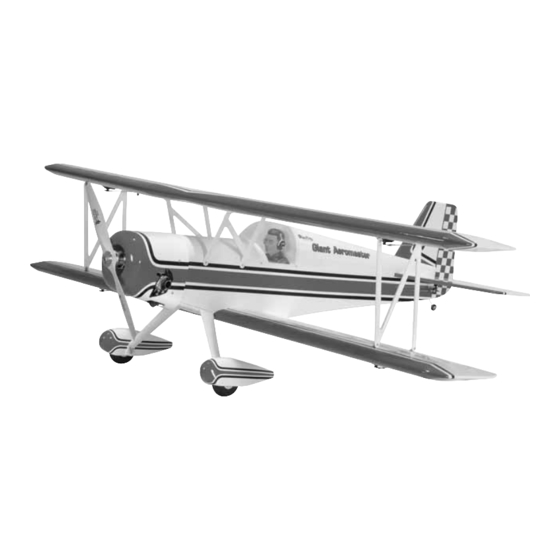
Wingspan: 73 in [1855mm]
Wing Area: 1880 sq in [121dm
Weight: 16 – 18 lb [7710 – 8135g]
Wing Loading: 20 – 22 oz/sq ft [60 – 67g/dm
Length: 63 in [1600mm]
Radio: Minimum required 6-channel radio,
6 standard servos with 70+ oz-in of torque
Engine: 1.6 – 2.13 cu in [26 – 35cc] two-stroke (Glow)
1.8 – 3.7 cu in [30 – 60cc] (Gas)
Great Planes
®
Model Manufacturing Co. guarantees this kit to be free from defects in both material and workmanship at the date of purchase. This
warranty does not cover any component parts damaged by use or modification. In no case shall Great Planes' liability exceed the original cost of
the purchased kit. Further, Great Planes reserves the right to change or modify this warranty without notice.
In that Great Planes has no control over the final assembly or material used for final assembly, no liability shall be assumed nor accepted for any
damage resulting from the use by the user of the final user-assembled product. By the act of using the user-assembled product, the user accepts all
resulting liability.
If the buyer is not prepared to accept the liability associated with the use of this product, the buyer is advised to return this kit immediately
in new and unused condition to the place of purchase.
To make a warranty claim send the defective part or item to Hobby Services at the address below:
Include a letter stating your name, return shipping address, as much contact information as possible (daytime telephone number, fax number, e-mail
address), a detailed description of the problem and a photocopy of the purchase receipt. Upon receipt of the package the problem will be evaluated as
quickly as possible.
READ THROUGH THIS MANUAL BEFORE STARTING
CONSTRUCTION.
INSTRUCTIONS AND WARNINGS CONCERNING
THE ASSEMBLY AND USE OF THIS MODEL.
Entire Contents © Copyright 2006
INSTRUCTION MANUAL
]
2
2
]
3002 N. Apollo Dr., Suite 1
IT
CONTAINS
WARRANTY
Hobby Services
Champaign, IL 61822
USA
IMPORTANT
Champaign, IL
(217) 398-8970, Ext. 5
airsupport@greatplanes.com
GPMZ1225 for GPMA1225 V1.0
Advertisement
Table of Contents

Related Manuals for GREAT PLANES Giant Aeromaster ARF


Summary of Contents for GREAT PLANES Giant Aeromaster ARF
-
Page 1: Instruction Manual
Further, Great Planes reserves the right to change or modify this warranty without notice. In that Great Planes has no control over the final assembly or material used for final assembly, no liability shall be assumed nor accepted for any damage resulting from the use by the user of the final user-assembled product. -
Page 2: Table Of Contents
Engine Recommendations...........4 For the latest technical updates or manual corrections to the ADDITIONAL ITEMS REQUIRED ........4 Giant Aeromaster ARF visit the Great Planes web site at Hardware & Accessories ..........4 www.greatplanes.com. Open the “Airplanes” link, and then Adhesives & Building Supplies ........4 select the Giant Aeromaster ARF. -
Page 3: Decisions You Must Make
(fuel tank, wheels, etc.) throughout the building process. The Giant Aeromaster ARF has different setup options for 5. You must correctly install all R/C and other components the ailerons and elevator functions that will alter the radio so that the model operates correctly on the ground and in gear required for completion. -
Page 4: Engine Recommendations
Aeromaster ARF is specified on the cover of this manual. All engines within the specified range will power this model well. Never fly the Giant Aeromaster ARF with an engine In addition to common household tools and hobby tools, this larger than one in the specified range because it has not is the “short list”... -
Page 5: Optional Supplies & Tools
Optional Supplies & Tools This is a number four screw that is 1-1/2" [38mm] long Here is a list of optional tools mentioned in the manual that will help you build the Giant Aeromaster ARF. with forty threads per inch. ❏... -
Page 6: Ordering Replacement Parts
ORDERING REPLACEMENT PARTS COMMON ABBREVIATIONS Replacement parts for the Great Planes Giant Aeromaster Fuse = Fuselage ARF are available using the order numbers in the Stab = Horizontal Stabilizer Replacement Parts List that follows. The fastest, most Fin = Vertical Fin... -
Page 7: Kit Inspection
If any parts are missing or are not of acceptable quality, or if you need assistance with assembly, contact Product Support. When reporting defective or missing parts, use the part names exactly as they are written in the Kit Contents list. Great Planes Product Support 3002 N. Apollo Drive, Suite 1 Champaign, IL 61822 Telephone: (217) 398-8970, ext. -
Page 8: Check Kit Contents
CHECK KIT CONTENTS ❏ 1. If you have not done so already, remove the major parts of the kit from the box (wings, fuselage, cowl, tail parts, etc.) and inspect them for damage. Be sure to label the ailerons in some way to remind you of which wing panel they belong to. -
Page 9: Install The Aileron Servos
Install the Ailerons Servos Note: There are two options for aileron installation on the Giant Aeromaster ARF. One option is to use two bottom aileron servos to drive all four ailerons. The second option is to install an aileron servo for each of the four ailerons. You will repeat the following steps for the top wing if you choose ❏... -
Page 10: Join The Bottom Wing
Join the Bottom Wing ❏ ❏ 4. Securely attach the string to the end of the servo lead. The other end of the string is attached with tape on the inside of the wing near the root. Pull this end of the string up and through the small 1/2"... -
Page 11: Join The Top Wing
❏ 8. Slide the other wing panel onto the wing joiners and Connect the Ailerons Pushrods press the two panels together. Clean up any epoxy that squeezes out with a paper towel and alcohol. ❏ ❏ 1. The following photos and procedures will show the ❏... - Page 12 ❏ ❏ 8. Trim the pushrod so that 1/8" [3.2mm] extends into the clevis when the clevis is positioned at the mark made in step 7. ❏ ❏ 9. Solder the clevis onto the pushrod using the following Expert Tip . HOW TO SOLDER A.
-
Page 13: Assemble The Fuselage
❏ 4. Insert a T-pin into the fuselage near the nose and along the centerline. Attach a piece of non-elastic string, such as kite string or Kevlar ® thread, to the T-pin that is long enough to reach the stabilizer. Measure the distance from ❏... -
Page 14: Attach The Rudder & Tailwheel
sides of the stabilizer. Be careful not to cut into the wood structure as this could weaken the stabilizer. HOW TO CUT COVERING FROM BALSA Use a soldering iron to cut the covering from the stab. The tip of the soldering iron doesn’t have to be sharp, but a fine-tip does work best. -
Page 15: Attach The Main Landing Gear
small metal file. Replace the wheel collar and secure it with Attach the Main Landing Gear the set screw. Apply a drop of thread-locking compound to the set screw prior to securing the wheel collar. ❏ ❏ 1. Locate the main landing gear, two 4" [102mm] wheels, four 3/16"... -
Page 16: Servo Installation
SERVO INSTALLATION Elevator Servo Installation ❏ ❏ 7. Grind flat spots on the axle where the set screws in the wheel collar will seat. ❏ ❏ 8. Reattach the wheel collars, wheel, and wheel pant. Apply thread-locking compound to the set screws to prevent them from backing out. -
Page 17: Rudder Servo Installation
horn. If the control surface is not at neutral, unsnap the clevis and adjust as needed. ❏ ❏ 11. When done adjusting the clevis, tighten the 4-40 hex nut against the clevis. Be sure to use a drop of Threadlocker to prevent the nut from backing off. ❏... - Page 18 ❏ 5. Insert the hook and loop material in the front hatch area as shown. ❏ 2. Use a rotary tool such as a Dremel with a small round sanding bit, or a razor saw, to cut away the wood inside the ❏...
-
Page 19: Fuel Tank Assembly (Gas Engine)
❏ 9. Follow your manufacturer’s directions for connecting the grounding wire, spark plug wire and ignition to the engine. ❏ 3. Write “TOP” on the back of the tank so you will know which way to install it after you have inserted the stopper Fuel Tank Assembly (Gas Engine) assembly. -
Page 20: Fuel Tank Assembly (Glow Engine)
2. Insert the fuel tank into the fuselage. Route the fuel [184mm]. Mark the location of the engine on the engine lines through the circular cutout in the first former behind mount. The Great Planes Dead Center ™ Hole Locator the firewall. -
Page 21: Install The Throttle Servo & Pushrod (Gas Engine)
❏ 4. Mount the throttle servo as shown in the photo. ❏ 5. Use two rubber bands to hold the fuel tank in place as shown. ❏ 6. Connect the fuel lines to your engine setup as needed. Install the Throttle Servo & Pushrod (Gas Engine) ❏... -
Page 22: Install The Throttle Servo & Pushrod (Glow Engine)
❏ 1. Locate one 2-56 x 36" [914mm] threaded pushrod. on the Giant Aeromaster ARF, the following section should be Thread the nylon clevis 14 turns onto the threaded end of used only as a guide for your installation. The Fuji-Imvac the pushrod and install a silicone clevis retainer. -
Page 23: Attach The Wings & Cabanes
ATTACH THE WINGS & CABANES ❏ 1. Attach the bottom wing to the fuselage with the 1/4-20 nylon wing bolts. ❏ 2. Locate eight metal interplane or “N” strut mounting ❏ 5. Apply a piece of masking tape to each block. Measure brackets. -
Page 24: Connect The Aileron Joiner Rods
❏ 12. Without disturbing the top wing, verify that the lower cabane mounting holes are positioned over the hardwood blocks located in the fuselage, just under the covering. If they are not, check to see if you have mounted the center cabanes and “N”... -
Page 25: Final Details
❏ ❏ 3. With the aileron centered, rotate the joiner rod straight up 2. Wrap the receiver and receiver battery in 1/4" [6.4mm] to meet the bottom of the top wing aileron. Attach a nylon foam and secure it to the servo tray as shown using the control horn on the bottom of the top wing aileron. -
Page 26: Set The Control Throws
If, after you have become accustomed to the way the eliminate any additional ballast required. If additional weight is Giant Aeromaster ARF flies, you would like to change the required, nose weight may be easily added by using a throws to suit your taste, that is fine. -
Page 27: Balance The Model Laterally
We use a Top Flite Precision Magnetic Prop Balancer (TOPQ5700) in the workshop and keep a Great Planes Fingertip Prop Balancer (GPMQ5000) in our flight box. PREFLIGHT Ground Check If the engine is new, follow the engine manufacturer’s... -
Page 28: Engine Safety Precautions
various speeds with an assistant holding the model, using AMA SAFETY CODE (excerpts) hand signals to show you what is happening. If the control surfaces do not respond correctly, do not fly! Find and correct the problem first. Look for loose servo connections or broken wires, corroded wires on old servo connectors, poor solder Read and abide by the following excerpts from the Academy joints in your battery pack or a defective cell, or a damaged... -
Page 29: Imaa Safety Code (Excerpts)
5.1 Magneto spark ignition engines must have a coil- grounding switch on the aircraft to stop the engine. This will Since the Giant Aeromaster ARF qualifies as a “giant- also prevent accidental starting of the engine. This switch scale” model and is therefore eligible to fly in IMAA shall be readily available to both pilot and spotter/helper. -
Page 30: Check List
Dependable, redundant and fail-safe battery systems Propeller tips should be painted or colored in a visible and are recommended. contrasting manner to increase the visibility of the propeller tip arc. The use of anti-glitch devices for long leads is recommended. CHECK LIST There is no maximum engine displacement limit, as it is the position of this body that an underpowered aircraft presents... -
Page 31: Flying
“buzz,” this may indicate control Take it easy with the Giant Aeromaster ARF for the first few surface flutter . Flutter occurs when a control surface flights, gradually getting acquainted with it as you gain (such as an aileron or elevator) or a flying surface (such confidence. - Page 32 Level the attitude when the OTHER ITEMS AVAILABLE FROM model reaches the runway threshold, modulating the throttle GREAT PLANES as necessary to maintain your glide path and airspeed. If you are going to overshoot, smoothly advance the throttle (always ready on the right rudder to counteract torque) and climb out to make another attempt.
Need help?
Do you have a question about the Giant Aeromaster ARF and is the answer not in the manual?
Questions and answers