Table of Contents
Advertisement
Quick Links
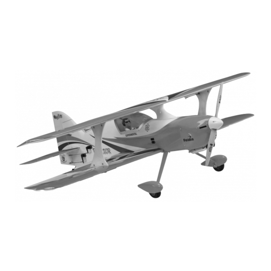
ARF .61-.91 SPORT BIPLANE
Great Planes
®
Model Manufacturing Co. guarantees this kit to
be free from defects in both material and workmanship at the date
of purchase. This warranty does not cover any component parts
damaged by use or modifi cation. In no case shall Great Planes'
liability exceed the original cost of the purchased kit. Further,
Great Planes reserves the right to change or modify this warranty
without notice.
In that Great Planes has no control over the fi nal assembly or
material used for fi nal assembly, no liability shall be assumed nor
accepted for any damage resulting from the use by the user of
the fi nal user-assembled product. By the act of using the user-
assembled product, the user accepts all resulting liability.
If the buyer is not prepared to accept the liability associated
with the use of this product, the buyer is advised to return
READ THROUGH THIS MANUAL BEFORE STARTING CONSTRUCTION. IT CONTAINS IMPORTANT
INSTRUCTIONS AND WARNINGS CONCERNING THE ASSEMBLY AND USE OF THIS MODEL.
Entire Contents © Copyright 2008
INSTRUCTION MANUAL
™
WARRANTY
this kit immediately in new and unused condition to the place
of purchase.
To make a warranty claim send the defective part or item to Hobby
Services at the address below:
Champaign, IL 61822 USA
Include a letter stating your name, return shipping address, as
much contact information as possible (daytime telephone number,
fax number, e-mail address), a detailed description of the problem
and a photocopy of the purchase receipt. Upon receipt of the
package, the problem will be evaluated as quickly as possible.
airsupport@greatplanes.com
Top Wingspan: 48 in [1220mm]
Bottom Wingspan: 48 in [1220mm]
Total Wing Area: 1145 sq in [73.9 dm
Weight: 7–7.5 lb [3170–3400 g]
Wing Loading: 14–15 oz/sq ft [43–46 g/dm
Length: 58.5 in [1485mm]
Engine: .61 cu in [10cc] two-stroke,
.70–.91 cu in [11.5–15.0cc] four-stroke,
™
RimFire
Hobby Services
3002 N. Apollo Dr., Suite 1
Champaign, Illinois
(217) 398-8970, Ext 5
2
]
2
]
Radio: 4–5 ch.
.80 (50-55-500kV)
GPMA1023Mnl1.0
Advertisement
Table of Contents

Related Manuals for GREAT PLANES Reactor ARF .61-.91 SPORT BIPLANE


Summary of Contents for GREAT PLANES Reactor ARF .61-.91 SPORT BIPLANE
-
Page 1: Instruction Manual
READ THROUGH THIS MANUAL BEFORE STARTING CONSTRUCTION. IT CONTAINS IMPORTANT INSTRUCTIONS AND WARNINGS CONCERNING THE ASSEMBLY AND USE OF THIS MODEL. Champaign, Illinois (217) 398-8970, Ext 5 airsupport@greatplanes.com Entire Contents © Copyright 2008 GPMA1023Mnl1.0... -
Page 2: Table Of Contents
Hook up the Throttle ..........18 the Reactor .60 biplane, visit the Great Planes web site at Mount the Cowl ............18 www.greatplanes.com. Open the “Airplanes” link, then ASSEMBLE THE WINGS ..........22 select the Reactor .60 biplane ARF. If there is new technical Mount the Aileron Servos ......... -
Page 3: Safety Precautions
DECISIONS YOU MUST MAKE PROTECT YOUR MODEL, YOURSELF & OTHERS...FOLLOW THESE Engine Recommendations IMPORTANT SAFETY PRECAUTIONS The recommended engine sizes for the Reactor .60 biplane 1. Your Reactor .60 Bipe should not be considered a toy, but are specifi ed on the cover of this instruction manual. If you rather a sophisticated, working model that functions very haven’t yet decided whether to go 2-stroke or 4-stroke, one much like a full-size airplane. -
Page 4: Radio/Servo Recommendations
Following are the items illustrated in the instruction Another critically important component of the motor battery manual for equipping your Reactor .60 biplane with an charging system is a cell balancer. LiPo battery technology is electric motor: so powerful that each, individual cell within the battery pack should be charged equally—or balanced. - Page 5 Here is some technical data for the suggested servos to AILERON SERVO WIRE EXTENSIONS: assist you in making a decision: Same as for the elevator and rudder servos, if using digital servos, be certain to use compatible servo extensions. Speed Torque (@ 4.8V) Weight (sec./60°...
-
Page 6: Additional Items Required
Great Planes 1/5-Scale Sport pilot: measurements anyway. To view this information visit the web GPMQ9015 Red, GPMQ9016 Blue, site at www.greatplanes.com and click on “Technical Data.” GPMQ9017 Yellow, GPMQ9018 Unpainted Due to manufacturing tolerances which will have little or no ❏... -
Page 7: Kit Inspection
GPMA3352 ..Fuel Tank Telephone: (217) 398-8970, ext. 5 Fax: (217) 398-7721 NOTE: Full-size plans are not available. You can download a E-mail: airsupport@greatplanes.com copy of this manual at www.greatplanes.com. KIT CONTENTS 1. Cowl 6. Horizontal Stab 11. Main Wheels 2. -
Page 8: Preparation
PREPARATION ASSEMBLE THE FUSELAGE Test-Mount the Elevator and Rudder Servos It will be easier to cut the covering from the servo mounts and drill the servo mounting screws now, before the horizontal stabilizer is glued into position. ❏ 1. Use a covering iron with a cover sock to tighten the covering or remove any wrinkles found on parts of the model. -
Page 9: Mount The Horizontal Stabilizer (Stab)
Mount the Horizontal Stabilizer (Stab) ❏ 2. Test fi t the servos in the servo openings in the fuselage. If using standard-size servos that don’t fi t in the openings, use a fi ne-point felt-tip pen and the plywood servo cutout ❏... - Page 10 B = B' ❏ 7. Fold a piece of masking tape over the other end of the string end and mark a line on it. Pull the string to the tip of one side of the stab. Slide the tape along the string until the line on the tape aligns with the tip.
-
Page 11: Hinge The Elevators And Rudder
❏ 3. Join the matching elevator to the stab and take out the T-pins. Make sure there is a small hinge gap—just enough to see light through or to slip a piece of paper through. ❏ 10. Slide the stab into position, then partially out the other side, exposing the uncovered balsa on the other side of the stab. -
Page 12: Hook Up The Elevator And Rudder
Hook Up the Elevator and Rudder ❏ 1. Connect your servo extensions to the rudder and elevator servos. Secure the connectors with 1-1/2" [38mm] pieces of heat shrink tubing cut from the 3" [76mm] tubing supplied. Use a heat gun or a hobby torch to shrink the tubing. Refer to these photos while hooking up the elevator and rudder servos. - Page 13 We’re going to instruct you to center the servos and adjust the pushrods now, but this could be done later during fi nal setup if you prefer. ❏ 3. Temporarily connect the servos to your receiver with a HOW TO SOLDER battery and a switch so you can move the servos with your transmitter.
-
Page 14: Mount The Main Landing Gear
Mount the Main Landing Gear ❏ 1. Use a 1/2" wrench and a 7/32" wrench (or crescent wrenches) to fasten a 5/32" x 1-1/4" [4mm x 32mm] bolt-on axle to each fi berglass main landing gear leg with a 5/16"-24 lock nut. - Page 15 BATTERY MOUNT PLATE 7" [178mm] 5-1/2" [140mm] “HOOK” SIDE “LOOP” SIDE 2" [51mm] OVERLAP ❏ 4. Test fi t the battery and the mounting plate in the fuselage—note that the tabs in the front of the mounting plate key into the notches in the back of the fi rewall and that the sides of the mounting plate are locked into the former near the rear.
-
Page 16: Mount The Engine
Mount the Engine (A 4-stroke is shown in the photos, but the procedure for a 2-stroke is the same.) ❏ 1. Temporarily mount the included Great Planes .60-1.20 adjustable motor mount to the fi rewall with four 8-32 x 1" [25.4mm] SHCS and #8 fl... -
Page 17: Install The Fuel Tank
O.S. .61FX O.S. FS91 II, O.S. FS81 O.S. FS91 II PUMP ❏ ❏ 6. Before-mounting the engine, drill 3/16" [4.8mm] holes 3. Glue both plywood fuel tank rings to the back of the through the fi rewall at the crossmarks that align with the fi... -
Page 18: Hook Up The Throttle
Hook Up the Throttle Refer to these photos and sketches while hooking up the throttle. GUIDE TUBE SUPPORTS SCREW-LOCK PUSHROD 4-40 x 1/8" [3.2mm] SHCS CONNECTOR (USE THREADLOCKER) 2-56 PUSHROD ❏ NYLON 1. Glue in the plywood throttle servo tray and hook up RETAINER the throttle using the 36"... - Page 19 ❏ 1. Take an estimated measurement of where the engine head will protrude from the cowl. In this case the front of the cutout will be approximately 4-1/2" [115mm] from the back of the cowl. ❏ 4. Continue to fi t, mark and cut the cowl as necessary until you can get it at least partially into position.
- Page 20 ❏ ❏ 6. Make four templates with holes from thin cardstock to be 10. Remove the cardstock templates. Reposition the cowl used for marking the screw holes once the cowl is in position. and spinner. Holding the cowl in position, use the holes in the Tape the templates to the fuselage with the holes in the cowl as a guide for drilling four 3/32"...
- Page 21 ❏ 14. Cut any other holes in the cowl necessary for the needle valve, engine cooling, glow plug, etc. For the needle valve, it is convenient to use a paper template. ❏ 13. Same as when cutting holes for the engine, when cutting holes for the muffl...
-
Page 22: Assemble The Wings
❏ Here’s a photo of the fi nished cowl with all necessary cuts. 2. Hold two servo mounting blocks to one of the aileron servos with pieces of thin cardstock between each block and the servo and under the servo—if using standard-size servos use two of the larger blocks, if using smaller servos like the 3102s use one of the smaller mounting blocks on the end ASSEMBLE THE WINGS... -
Page 23: Mount The Wings
Refer to this photo while hooking up the ailerons. ❏ 7. Mount the hatches in the wing with #2 x 3/8" [9.5mm] button-head screws. This will require a .050" ballwrench, as mentioned in the front of this manual. ❏ 8. The same as was done for the elevators and rudder, make the pushrods and connect the bottom ailerons to the servos using the hardware shown. - Page 24 1/16" WING BOLT PLATE [2mm] REMOVE THE COVERING 7/16" [11.1mm] 3/16" [4.8mm] ❏ 3. Remove the tabs. Apply 30-minute epoxy in the slots in the wing and to the tabs. Push the tabs into the slots. Wipe away any excess epoxy that squeezes out. Proceed immediately to the next step.
- Page 25 ❏ 10. Use 30-minute epoxy to glue the top wing dowels into the top wing. Wipe away any excess epoxy, then fi t the wing brace over the dowels while the epoxy is hardening. Use care not to inadvertently glue the wing brace to the dowels or the wing.
-
Page 26: Mark The Balance Point (C.g.)
Mark the Balance Point (C.G.) RECOMMENDED STARTING BALANCE POINT 5-1/4" [133mm] FROM THE LEADING EDGE OF THE MIDDLE OF THE TOP WING The balance point (C.G.) is to be marked on the bottom of the top wing. It will be easier to do this now, before- mounting the wing to the fuselage. -
Page 27: Final Assembly
Final Radio Installation FINAL ASSEMBLY Refer to this photo while fi nishing the radio installation. Mount the Canopy ❏ 1. Wrap the receiver and receiver battery in 1/4" [6.4mm] R/C foam. Mount the battery and receiver to the plywood receiver/ battery tray inside the fuselage with straps made from the ❏... -
Page 28: Get The Model Ready To Fly
There are two ways to connect multiple battery packs: In Now that the model is fully assembled and all of the Series and in Parallel. external systems/components have been installed, access to the inside of the model will probably no longer These are two 3200mAh batteries (one 11.1V be necessary. -
Page 29: Check The Control Directions
Set the Control Throws NO!! To ensure a successful fi rst fl ight, set up your Reactor .60 biplane according to the control throws provided on page 31. The throws have been determined through fl ight testing and record-keeping allowing the model to perform in the manner in which it was intended. -
Page 30: Proper Pushrod Hookup
Proper Pushrod Hookup Avo i d i ng Flu t t e r, M axim i z ing S e rvo O u t p u t To rqu e Note: Your control horn may vary. When connecting pushrods and setting up your control CONTROL throws, critically... -
Page 31: Assemble The Balance Stand
❏ 4. Measure and set the low rate elevator throws and the high and low rate throws for the rest of the control surfaces the same way. These are the recommended control surface throws: 3D RATE HIGH RATE LOW RATE Down Down Down... -
Page 32: Balance The Model Laterally
❏ 3. If the tail drops, the model is “tail heavy.” The battery PREFLIGHT pack and/or receiver could be moved forward to get the model to balance, or weight could be added to the nose. If the nose drops, the model is “nose heavy” and the battery pack and/or Identify Your Model receiver could be moved aft, or weight could be added to the tail. -
Page 33: Ground Check
• To stop a glow engine, cut off the fuel supply by closing Ground Check off the fuel line or following the engine manufacturer’s recommendations. Do not use hands, fi ngers or any other If using a glow engine, run the engine for a few minutes body part to try to stop the engine. -
Page 34: Check List
CHECK LIST FLYING The Reactor .60 biplane is a great-fl ying model that fl ies During the last few moments of preparation your mind may smoothly and predictably. The Reactor is, however, a very be elsewhere anticipating the excitement of the fi rst fl ight. “neutral”... -
Page 35: Flight
the throttle when at the correct altitude. Allow the nose to Flight drop so the plane will maintain suffi cient airspeed and simply bring the model in. If you’re coming in a little short, simply If you’re a less-experienced modeler, your fi rst priority will be add throttle to stretch the landing.
Need help?
Do you have a question about the Reactor ARF .61-.91 SPORT BIPLANE and is the answer not in the manual?
Questions and answers